 Vai al contenuto

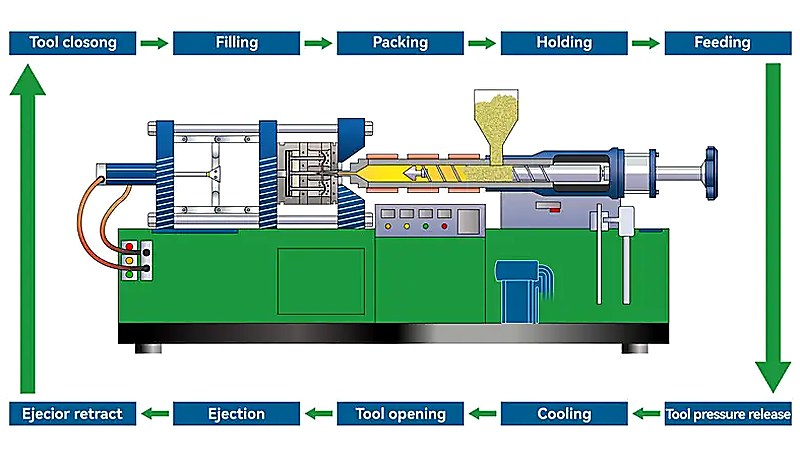
Getting stampaggio a iniezione1 process parameters right makes the difference between profitable production and expensive scrap. After 20 years of troubleshooting everything from warped automotive parts to sink marks in consumer electronics, I’ve learned that successful molding comes down to mastering five core parameters: temperature, pressure, speed, timing, and cooling. These aren’t just numbers on a machine display—they’re the levers that control your part quality, cycle time, and bottom line. If you are evaluating suppliers, check our sourcing guide3 for practical qualification tips.
- Temperature control affects material flow, crystallization, and surface finish—typically ranges from 180°C for PP to 280°C for PC
- Injection pressure determines cavity fill and part density, usually 800-1500 bar for most thermoplastics
- Speed parameters control shear heating and molecular orientation—injection speeds of 50-200 mm/s are common
- Holding pressure and time prevent shrinkage and sink marks—typically 60-80% of injection pressure for 3-15 seconds
- Cooling time directly impacts cycle time and part quality—calculate using wall thickness squared times material thermal diffusivity
What Are the Key Injection Molding Process Parameters?
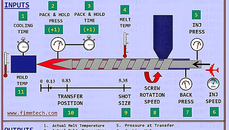
The key injection molding process parameters are the main categories or options explained in this section. The five critical injection moulding process parameters are temperature, pressure, speed, timing, and cooling—each controlling specific aspects of part quality and production efficiency. Temperature affects material viscosity and flow behavior. Pressure determines cavity filling and part density. Speed controls shear heating and molecular orientation. Timing manages material solidification. Cooling governs cycle time and dimensional stability.
Temperature parameters include barrel zones (typically 4-5 zones), nozzle temperature, and stampo a iniezione temperature. For ABS, I typically run barrel temperatures from 220°C at the feed zone to 240°C at the nozzle, with mold temperatures around 60-80°C. These temperatures ensure proper melt flow while preventing degradation.
Pressure parameters work in sequence: injection pressure fills the cavity (800-1500 bar), holding pressure maintains part density (60-80% of injection pressure), and back pressure controls melt homogeneity (3-15 bar). Speed parameters include injection speed (50-200 mm/s), screw rotation speed (50-150 RPM), and ejection speed. Timing parameters cover injection time, holding time, cooling time, and total cycle time.
How Does Temperature Affect Injection Molding Quality?
Temperature directly controls material viscosity, flow length, surface finish, and molecular structure in injection molded parts. Higher temperatures reduce viscosity, allowing longer flow lengths and better cavity filling, but excessive heat causes degradation, flash, and poor surface quality. Lower temperatures increase viscosity, potentially causing short shots and high injection pressures.
Barrel temperature profiles typically increase from rear to front zones. For polypropylene, I run 180°C at the feed zone, 200°C in the compression zone, 210°C in the metering zone, and 220°C at the nozzle. This progressive heating ensures proper plasticization without overheating. The temperature difference between zones should be 10-20°C to prevent material degradation.
Mold temperature affects crystallization in semi-crystalline plastics like nylon and polypropylene. Higher mold temperatures (80-120°C for nylon) promote crystallinity, improving chemical resistance and dimensional stability but increasing cycle time. Lower mold temperatures (40-60°C) reduce cycle time but may cause warpage and poor surface finish. I’ve seen 20% cycle time increases when mold temperature rises from 60°C to 100°C for nylon parts.
“Increasing barrel temperature by 10°C typically reduces injection pressure requirements by 50-100 bar for most thermoplastics.”Vero
This relationship holds true because higher temperatures reduce melt viscosity, making the material flow more easily through the runner system and into the mold cavity. I’ve consistently observed this 50-100 bar pressure reduction when optimizing process parameters for materials like ABS, PC, and nylon.
“Faster injection speeds always improve part quality by reducing flow marks and hesitation lines.”Falso
While faster injection can improve surface finish in many cases, excessive speed creates problems including high shear heating, molecular orientation leading to warpage, and increased injection pressures. Optimal injection speed depends on part geometry, wall thickness, and material properties. I’ve seen warpage increase 30% when injection speed exceeded 250 mm/s in thin-wall PC parts.
What Role Does Injection Pressure Play in Part Quality?
Injection pressure determines cavity filling completeness, part density, and dimensional accuracy by forcing molten plastic through runners, gates, and into every detail of the mold cavity. Insufficient pressure causes short shots, sink marks, and low part density. Excessive pressure leads to flash, high residual stress, and difficult part ejection.
Typical injection pressures range from 800-1500 bar for most thermoplastics, but thin-wall applications may require 1800+ bar. I calculate required pressure using flow length, wall thickness, and material viscosity. For a 200mm flow length through 2mm wall thickness in ABS, expect 1000-1200 bar injection pressure at standard processing temperatures.
Holding pressure maintains part quality after cavity filling by compensating for material shrinkage during cooling. Set holding pressure at 60-80% of injection pressure—too low causes sink marks and dimensional variations, too high wastes energy and may cause flash. Holding time should be 3-15 seconds, depending on wall thickness and material thermal properties. For thick sections (>5mm), extend holding time to 10-15 seconds.
How Do Speed and Timing Parameters Shape the Final Product?
Speed and timing parameters control material flow behavior, molecular orientation, and part solidification, directly affecting surface finish, mechanical properties, and dimensional stability. Injection speed determines shear heating and flow front advancement through the cavity. Screw speed affects melt homogeneity and color dispersion. Timing parameters manage material phase transitions from liquid to solid state, governing how long each stage lasts and when transitions occur. Getting these parameters right requires understanding the interaction between material rheology, part geometry, and cooling capacity of the mold.
Injection speed typically ranges from 50-200 mm/s, but optimal speed depends on part geometry and material sensitivity. Fast injection (150-200 mm/s) improves surface finish and reduces flow marks but increases shear heating and molecular orientation. Slow injection (50-100 mm/s) reduces stress but may cause flow marks and temperature variations. I use multi-stage injection profiles: fast filling for 90% cavity volume, then slow speed for final 10% to minimize stress.
Screw rotation speed affects melt quality and cycle time. Standard speeds of 50-150 RPM provide good mixing without excessive shear heating. Higher speeds above 200 RPM cause degradation in heat-sensitive materials like PVC and POM, leading to discoloration and reduced mechanical properties. Lower speeds below 50 RPM may produce poor melt homogeneity, resulting in color streaking or inconsistent part quality. Back pressure of 3-15 bar improves mixing—use higher values (10-15 bar) for recycled materials or color-critical applications where uniform appearance is essential. I typically start with 8-10 bar back pressure and adjust based on melt temperature monitoring and visual inspection of test shots.
Why Is Mold Temperature Critical for Crystalline Plastics?
Mold temperature controls crystallization kinetics in semi-crystalline plastics like nylon, polypropylene, and POM, directly affecting mechanical properties, chemical resistance, and dimensional stability. Higher mold temperatures promote crystal formation, improving strength and chemical resistance but increasing cycle time. Lower temperatures limit crystallization, reducing properties but enabling faster production.
For nylon 66, I typically run mold temperatures of 80-120°C depending on part requirements. High-performance applications requiring maximum strength and chemical resistance need 100-120°C mold temperature, achieving 40-50% crystallinity. Consumer products prioritizing cost over performance can use 60-80°C, accepting lower crystallinity (20-30%) for faster cycles.

Polypropylene shows dramatic property changes with mold temperature. At 40°C mold temperature, expect 30-40% crystallinity with good impact resistance. At 80°C, crystallinity increases to 50-60% with higher stiffness but reduced impact strength. The key is matching mold temperature to application requirements—automotive under-hood parts need high crystallinity, while flexible packaging prefers lower crystallinity. I once ran tests on a PP gear housing where raising mold temperature from 50°C to 85°C increased tensile strength by 18% but nearly doubled cycle time. That tradeoff between mechanical performance and throughput is one every process engineer must evaluate carefully. POM follows a similar pattern—80-100°C mold temperatures produce better creep resistance for gears and mechanical components.
Parameter-related defects follow predictable patterns that experienced molders recognize immediately. Short shots indicate insufficient pressure or temperature preventing complete cavity fill. Flash suggests excessive pressure or worn tooling allowing material to escape the mold parting line. Sink marks result from inadequate holding pressure or insufficient holding time during cooling. Warpage stems from uneven cooling, excessive molecular orientation, or improper gate location creating differential shrinkage. Understanding which parameter causes each defect type is the first step toward systematic troubleshooting. I always start by checking the easiest parameter to adjust before moving to more complex causes—this diagnostic approach saves hours of trial-and-error debugging on the production floor.
For short shots, first increase injection pressure by 50-100 bar increments until the cavity fills completely. If pressure reaches machine limits above 1500 bar without improvement, increase barrel temperature by 10°C steps to reduce melt viscosity. Check for gate freeze-off by extending holding time—sometimes the gate seals before the cavity fills. Verify adequate venting as well, since trapped air prevents complete filling even at high pressures. On one automotive connector project, we traced persistent short shots to a blocked vent channel that was limiting air escape during high-speed filling.
Flash elimination requires systematic pressure reduction and mold inspection. Reduce injection pressure by 50 bar steps until flash disappears, then optimize holding pressure. Check parting line condition—worn or damaged mold surfaces cause flash at low pressures. Verify mold clamping force meets calculated requirements based on projected part area and cavity pressure.
Sink mark correction focuses on holding pressure and time optimization. Increase holding pressure to 70-80% of injection pressure. Extend holding time until gate freezes—typically 3-15 seconds depending on gate size and material. For thick sections, consider sequential valve gating or gas-assist molding to maintain pressure throughout cooling.
“Warpage in injection molded parts is primarily caused by differential shrinkage between thick and thin sections rather than material properties.”Vero
Differential shrinkage creates internal stresses that cause warpage as parts cool and solidify. Thick sections cool slower and shrink more than thin sections, creating stress concentrations. This is why uniform wall thickness design is critical—I’ve reduced warpage by 60% simply by maintaining consistent 2-3mm wall thickness in complex housings.
“Back pressure settings above 20 bar are always necessary for achieving good color mixing in injection molding.”Falso
While back pressure improves mixing, excessive values (>20 bar) cause unnecessary shear heating, longer cycle times, and potential material degradation. Most applications achieve excellent color mixing with 5-15 bar back pressure. I’ve found that 8-12 bar provides optimal mixing for most materials without the negative effects of excessive shear.
At ZetarMold, our 20+ years of injection molding experience across 47 machines ranging from 90T to 1850T has taught us that process parameter optimization is both science and art. Working with 400+ different materials, we’ve developed parameter databases that reduce setup time by 70% and first-shot success rates above 85%. Our process engineers use statistical process control to maintain parameter stability within ±2% across production runs.
Ready to optimize your injection molding process parameters? ZetarMold’s sourcing guide provides detailed parameter recommendations for over 400 materials. Our process engineers can help you establish robust parameter windows that ensure consistent quality while minimizing cycle time. Contact us for a free process parameter audit of your current molding operations.
Domande frequenti
What is the optimal injection molding temperature range for ABS?
ABS injection molding temperatures typically range from 220-250°C in the barrel with mold temperatures of 60-80°C. I recommend starting with 230°C barrel temperature and 70°C mold temperature for most general-purpose applications. Higher temperatures around 240-250°C improve flow and surface finish but increase the risk of thermal degradation. Lower temperatures around 220-230°C reduce cycle time but may cause short shots in thin-wall parts. Nozzle temperature should be set 5-10°C higher than the front barrel zone to prevent premature freeze-off. Always monitor actual melt temperature with a pyrometer—target 235-245°C for optimal ABS processing results.
How do you calculate the correct holding pressure for injection molding?
Calculate holding pressure as 60-80% of the injection pressure required for complete cavity filling. Start with 70% as baseline, then adjust based on part quality. For thick sections (>4mm), use 75-80% to prevent sink marks. For thin walls (<2mm), 60-65% prevents flash while maintaining density. Monitor part weight—consistent weight indicates proper holding pressure. I use cavity pressure sensors when available, targeting 400-600 bar cavity pressure during holding phase. Holding pressure too low causes sink marks and dimensional variation. Too high wastes energy and may cause flash or difficult ejection.
Cosa causa il flash nello stampaggio a iniezione e come si risolve?
Il flash si verifica quando la pressione di iniezione supera la forza di chiusura dello stampo o quando le superfici di separazione dello stampo sono usurate o danneggiate. Calcolare la forza di chiusura necessaria utilizzando l'area proiettata del pezzo moltiplicata per la pressione della cavità—tipicamente 3-5 tonnellate per pollice quadrato di area proiettata. Ridurre la pressione di iniezione con incrementi di 50-100 bar finché il flash scompare. Controllare le condizioni dello stampo—linee di separazione usurate, sfoghi danneggiati o manutenzione insufficiente dello stampo causano flash a pressioni normali. Verificare il corretto allineamento dello stampo e un'adeguata estensione delle barre di collegamento. A volte il flash indica una sfogiatura insufficiente, che richiede una riduzione della pressione o canali di sfogo aggiuntivi. La viscosità del materiale influisce sulla tendenza al flash—i materiali con un indice di flusso più alto generano flash più facilmente.
Qual è la differenza tra pressione di iniezione e pressione di mantenimento?
La pressione di iniezione riempie completamente la cavità dello stampo, tipicamente 800-1500 bar a seconda della geometria del pezzo e del materiale. La pressione di mantenimento mantiene la densità del pezzo durante il raffreddamento, solitamente il 60-80% della pressione di iniezione. La pressione di iniezione opera durante la fase di riempimento (1-3 secondi), mentre la pressione di mantenimento opera durante la solidificazione (3-15 secondi). Un'elevata pressione di iniezione garantisce un riempimento completo e una buona finitura superficiale. Una corretta pressione di mantenimento previene i segni di affondamento e il ritiro dimensionale. La transizione dalla pressione di iniezione a quella di mantenimento avviene al 95-98% del riempimento della cavità. Le macchine moderne utilizzano il feedback della pressione della cavità per ottimizzare automaticamente questo punto di commutazione.
Come influisce la velocità della vite sulla qualità della fusione della plastica?
La velocità della vite controlla l'intensità della miscelazione e il tempo di permanenza, influenzando direttamente l'omogeneità e la temperatura della fusione. Velocità standard di 50-150 RPM forniscono una buona miscelazione senza eccessivo riscaldamento da taglio. Velocità più elevate (>200 RPM) causano degradazione in materiali sensibili al calore come PVC o POM. Velocità più basse (<50 RPM) possono produrre una miscelazione del colore scadente o variazioni di temperatura. Regolo la velocità della vite in base alla sensibilità del materiale e ai requisiti di miscelazione. I materiali sensibili al calore necessitano di velocità più lente (50-100 RPM). I materiali riciclati o i concentrati di colore beneficiano di velocità più elevate (100-150 RPM). Monitorare la temperatura della fusione—una velocità eccessiva della vite aumenta la temperatura di 10-20°C attraverso il riscaldamento da taglio.
Qual è il tempo di raffreddamento ideale per i pezzi stampati a iniezione?
Il tempo di raffreddamento dipende dal quadrato dello spessore della parete e dalla diffusività termica del materiale. Utilizzare la formula: tempo di raffreddamento = (spessore della parete)² × fattore del materiale. Per l'ABS con uno spessore della parete di 3mm, prevedere un tempo di raffreddamento di 15-25 secondi. Il polipropilene si raffredda più velocemente (fattore del materiale 0,8), mentre il PC si raffredda più lentamente (fattore del materiale 1,3). La temperatura dello stampo influisce sul tempo di raffreddamento—ogni aumento di 10°C aggiunge il 15-20% al tempo del ciclo. Un design efficiente dei canali di raffreddamento riduce il tempo del 30-40%. Verifico un raffreddamento adeguato misurando la temperatura di espulsione del pezzo—dovrebbe essere inferiore a 60°C per la maggior parte dei termoplastici per prevenire deformazioni. Ottimizzare il tempo di raffreddamento attraverso una riduzione sistematica finché la qualità del pezzo non si degrada.
Come si imposta la contropressione per lo stampaggio a iniezione?
Impostare la contropressione tra 3-15 bar a seconda dei requisiti di miscelazione del materiale e delle esigenze di qualità. Iniziare con 5-8 bar per la maggior parte delle applicazioni, quindi regolare in base alla qualità della fusione. Una contropressione più alta (10-15 bar) migliora la miscelazione del colore e l'omogeneità della fusione ma aumenta il tempo del ciclo e il riscaldamento da taglio. Una contropressione più bassa (3-5 bar) riduce il tempo del ciclo ma può causare striature di colore o una miscelazione scadente. Materiali sensibili al calore come il PVC necessitano di una contropressione minima (3-5 bar). I materiali riciclati o le applicazioni con masterbatch beneficiano di valori più alti (10-12 bar). Monitorare la temperatura della fusione—una contropressione eccessiva aumenta la temperatura attraverso il riscaldamento da taglio. Regolare gradualmente con incrementi di 2-3 bar.
Cosa succede se la temperatura dello stampo è troppo bassa?
Una bassa temperatura dello stampo causa una finitura superficiale scadente, un riempimento incompleto della cavità, un'elevata tensione residua e un'instabilità dimensionale. I difetti superficiali includono segni di flusso, linee di saldatura e finitura opaca. I pezzi possono deformarsi durante l'uso a causa del rilascio delle tensioni. Le materie plastiche semicristalline come il nylon mostrano proprietà meccaniche ridotte a causa della cristallizzazione limitata. Ho osservato una riduzione della resistenza del 20-30% in parti in nylon stampate a 40°C rispetto a una temperatura dello stampo di 80°C. Una bassa temperatura dello stampo aumenta anche i requisiti di pressione di iniezione di 100-200 bar. Tuttavia, il tempo di raffreddamento diminuisce, migliorando il tempo del ciclo. L'equilibrio è fondamentale: utilizzare la temperatura minima che raggiunge una qualità accettabile del pezzo. Minimi tipici: ABS 50°C, nylon 60°C, polipropilene 40°C.
-
injection molding: injection molding refers to is the production process that melts plastic, injects it into a mold cavity, cools the part, and repeats the cycle for stable volume manufacturing. ↩
-
injection mold: injection mold refers to an injection mold is the precision tool that defines part geometry, cooling behavior, ejection, gating, surface finish, and repeatability. ↩
-
guida di approvvigionamento: La guida di approvvigionamento si riferisce a una guida di approvvigionamento che aiuta a valutare i partner di produzione in base alla capacità di utensilatura, al controllo del processo, alla conoscenza dei materiali, alla disciplina di ispezione e all'affidabilità. ↩


