 Vai al contenuto

Calcolo della area proiettata1 è uno dei primi e più critici passi in qualsiasi stampaggio a iniezione2 progetto. Sbagliare significa rischiare flash3 difetto, danneggiamento della macchina o incapacità di riempire lo stampo. Fallo correttamente, e potrai selezionare con sicurezza la pressa giusta, stimare la forza di chiusura e produrre pezzi di qualità fin dal primo giorno.
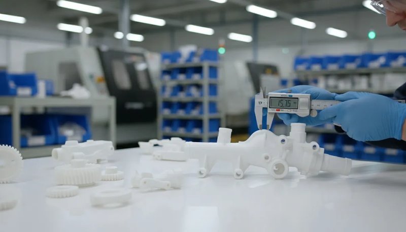
Nella nostra fabbrica di Shanghai, gestiamo 47 macchine per stampaggio a iniezione che vanno da 90T a 1850T. Ogni singolo progetto inizia con la stessa domanda: qual è l'area proiettata e la nostra attrezzatura ha una forza di chiusura sufficiente? Questa guida ti accompagna attraverso il processo di calcolo con formule reali, esempi pratici e consigli derivanti da due decenni di esperienza produttiva.
- L'area proiettata è la sagoma 2D del tuo componente lungo la direzione di chiusura
- Forza di Chiusura = Area Proiettata × Pressione in Cavità × Fattore di Sicurezza
- Includi sempre le aree del canale di colata e dell'ingresso nel tuo calcolo
- Le forme complesse possono essere suddivise in forme geometriche più semplici
- Un margine di sicurezza del 10-20% previene bave e iniezioni incomplete
Cos'è l'area proiettata nello stampaggio a iniezione?
L'area proiettata nello stampaggio a iniezione è l'ombra o la sagoma bidimensionale del vostro pezzo quando visto dalla direzione di chiusura dello stampo. Pensate a puntare una torcia direttamente sopra un oggetto — l'ombra che proietta sul tavolo è la sua area proiettata. Questa misura, tipicamente espressa in centimetri quadrati (cm²) o pollici quadrati (in), determina direttamente quanta forza di chiusura la vostra macchina necessita per mantenere lo stampo sigillato durante l'iniezione.
Per una visione più ampia, i nostri guida completa allo stampaggio a iniezione copre i fondamenti del processo, il comportamento dei materiali e le decisioni produttive.
If you are comparing vendors or planning procurement, our injection molding supplier sourcing guide covers RFQ prep, qualification, and commercial risk checks.
Why does it matter so much? When molten plastic enters the mold cavity under high pressure, it generates an outward force proportional to the projected area. If the machine’s clamping force is less than this outward force, the mold will open slightly at the parting line, causing flash — thin, unwanted fins of plastic along the edges of your part. In production environments, flash means rework, scrap, or rejected parts.
Nella nostra fabbrica di Shanghai, gestiamo 47 macchine per lo stampaggio a iniezione da 90T a 1850T. Ogni nuovo progetto inizia calcolando l'area proiettata per garantire di selezionare una pressa con adeguata capacità di chiusura — questo singolo calcolo previene costosi tentativi ed errori sul piano di produzione.
Come si Calcola l'Area Proiettata Passo dopo Passo?
L'area proiettata si calcola scomponendo il pezzo in forme geometriche di base, misurando ciascuna sagoma e sommando i risultati. Ecco il nostro metodo passo passo.
Passo 1: Determinare la Direzione di Chiusura
Prima di misurare qualsiasi cosa, identifica la direzione in cui lo stampo si apre e si chiude. Di solito è perpendicolare alla linea di divisione. L'area proiettata viene misurata lungo questo asse. Per la maggior parte dei pezzi standard, questa è la direzione in cui si muovono i piatti.
Passo 2: Suddividere il Pezzo in Forme Geometriche Semplici
Osservate il pezzo dalla direzione di chiusura. Suddividete il suo contorno in forme di base — rettangoli, cerchi, triangoli e trapezi. Ogni forma ha una formula di area nota:
Ecco le formule di base di cui avrai bisogno: Rettangolo = Lunghezza x Larghezza (es., 50 mm x 30 mm = 1.500 mm²); Cerchio = pi greco x raggio al quadrato (es., pi greco x 20² = 1.257 mm²); Triangolo = 0,5 x Base x Altezza (es., 0,5 x 40 x 25 = 500 mm²); Trapezio = 0,5 x (a + b) x h (es., 0,5 x (30 + 50) x 20 = 800 mm²).
Passo 3: Calcola ogni forma e sommale
Applica la formula appropriata a ciascuna sotto-forma, quindi somma tutte le aree. Per un pezzo che sembra un rettangolo con una linguetta semicircolare, calcolerai l'area rettangolare, l'area semicircolare e le sommerai.
Passo 4: Aggiungere le Aree del Canale di Colata e del Punto di Ingresso
Non dimenticare il sistema di canali. La plastica fusa attraversa canali e gate prima di entrare nella cavità. Questi canali generano anch'essi una forza verso l'esterno sullo stampo. Includi l'area proiettata del canale nel totale. Negli stampi a più cavità, moltiplica l'area della singola cavità per il numero di cavità, quindi aggiungi l'area totale dei canali.
Passo 5: Applicare la Correzione dell'Angolo di Sformo (Se Necessario)
Per pezzi con angoli di spoglia significativi, l'area proiettata potrebbe differire dalla misurazione dell'area piatta. La maggior parte degli angoli di spoglia (1-3 gradi) ha un impatto trascurabile, ma per pezzi a profondo stampaggio con angoli di spoglia di 5+ gradi, ricalcola la sagoma tenendo conto delle pareti inclinate. In pratica, questa correzione raramente supera il 2-3% dell'area totale.
Qual è la formula per la forza di chiusura dall'area proiettata?
Una volta ottenuta l'area proiettata, la formula della forza di chiusura è la chiave per selezionare la macchina giusta. L'equazione fondamentale è:
Forza di chiusura (kgf) = Area proiettata (cm²) × Pressione in cavità (kgf/cm²)
Conversione in tonnellate (dove 1 tonnellata = 1.000 kgf):
Tonnellaggio = [Area proiettata (cm²) × Pressione in cavità (kgf/cm²)] ÷ 1.000
La pressione in cavità dipende dal materiale stampato. Ecco i valori tipici di pressione in cavità per materiali comuni:
| Materiale | Pressione in cavità (kgf/cm2) | Pressione in Cavità (tonnellate/pollice quadrato) |
|---|---|---|
| PS (polistirolo) | 150–250 | 1,0–1,7 |
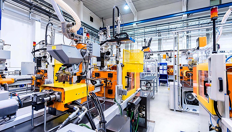
| PE (polietilene) | WM opera dal 1989 da Łódź, nella Polonia centrale. L'azienda combina lo stampaggio a iniezione della plastica con la lavorazione dei metalli, offrendo soluzioni complete dal concetto al prodotto finito. WM gestisce un moderno reparto di iniezione computerizzato e una sala attrezzi ben equipaggiata, consentendo loro di occuparsi sia della manutenzione degli stampi che della fabbricazione di nuovi utensili. | 1.4–2.1 |
| PP (polipropilene) | 200–350 | 1,4–2,5 |
| ABS | 300–500 | 2.1–3.5 |
| PA (Nylon) | 350–600 | 2.5–4.2 |
| PC (policarbonato) | 400–700 | 2.8–4.9 |
| POM (Acetal) | 350–550 | 2.5–3.9 |
| PBT | 350–550 | 2.5–3.9 |
Applicare sempre un fattore di sicurezza da 1.1 a 1.2 alla tonnellatura calcolata. Questo tiene conto delle variazioni di viscosità, dei cambiamenti di temperatura dello stampo e degli aggiustamenti di processo. Nella nostra pratica, utilizziamo tipicamente un margine di sicurezza del 15%.
How to Calculate Projected Area for Common Part Shapes?
Common shapes use standard geometry: length times width for rectangles, pi times radius squared for circles, and decomposition for complex parts.
Example 1: Flat Rectangular Part
A flat cover plate measures 120 mm × 80 mm. The mold clamps along the thin dimension (thickness direction), so the projected area is simply the face area:
Projected Area = 120 mm × 80 mm = 9,600 mm² = 96 cm²
If molded in ABS (cavity pressure ≈ 400 kgf/cm²), the required tonnage would be: Tonnage = (96 cm² × 400 kgf/cm²) ÷ 1,000 = 38.4 tons. With a 15% safety factor: 38.4 × 1.15 = 44.2 tons. A 50-ton press would handle this comfortably.
Example 2: Cylindrical Part
A cylindrical bushing with an outer diameter of 60 mm. The projected area is a circle:
Projected Area = π × r = 3.14159 × 30 = 2,827 mm² = 28.3 cm²
Note: if the cylinder is hollow, do NOT subtract the inner bore from the projected area. The clamping force acts on the full circular silhouette, not just the wall cross-section.
Example 3: L-Shaped Bracket
An L-shaped bracket can be divided into two rectangles: Rectangle A (60 × 40 mm) and Rectangle B (40 × 30 mm). If the two rectangles overlap by 40 × 30 mm, the total is:
Projected Area = (60 × 40) + (40 × 30) – (40 × 30) = 2,400 mm² = 24 cm²
The key principle: for any complex shape, decompose it into simple shapes, calculate each area, and add them together while subtracting any overlapping regions.
What Factors Affect the Projected Area Calculation?
Projected area accuracy is determined by four factors: part geometry, cavity count, runner design, and mold features like slides and lifters.
Part Geometry Complexity
Complex parts with ribs, bosses, undercuts, and varying wall thickness create projections that are not straightforward rectangles or circles. Use CAD software to extract the precise projected area from your 3D model. Most modern CAD packages (SolidWorks, Creo, NX) can calculate the projected area automatically along any axis.
Numero di cavità
In multi-cavity molds, the total projected area is the single-cavity projected area multiplied by the number of cavities, plus the runner system area. A four-cavity mold with a single-cavity area of 50 cm² and a runner area of 20 cm² has a total projected area of (4 × 50) + 20 = 220 cm².
Progettazione del sistema Runner
Cold runners add significant area. A full-round runner with 8 mm diameter running 150 mm across the mold adds 12 cm² to the projected area. Hot runner systems, while more expensive, reduce the projected area by eliminating the cold runner channel — which can sometimes allow the use of a smaller, less expensive press.
Mold Design Features
Slides, lifters, and core pulls can alter the effective projected area. Side-action slides, in particular, can introduce additional projected area at angles that is not immediately obvious from the top-down view. Always review the complete progettazione di stampi with your tooling engineer.

“Runner area must be included in projected area calculations for multi-cavity molds.”Vero
The runner system contributes 10-25% of the total projected area. Omitting it leads to underestimating tonnage, causing flash and mold separation during injection.
“You should subtract the inner bore from the projected area of a hollow cylindrical part.”Falso
The clamping force acts on the full circular silhouette of the part, including the hollow interior. The cavity pressure pushes outward against the entire projected area, not just the wall cross-section.
How Does Projected Area Influence Machine Selection?
Required machine tonnage is directly proportional to projected area. Undersizing causes flash, short shots, and dimensional defects in production.
With our fleet of machines from 90T to 1850T, we can match virtually any project to the right press. Here is how the math translates to machine selection:
When selecting a machine, also consider the platen size. The mold must fit within the machine platen, and the projected area should not exceed roughly two-thirds of the total platen area. If your projected area covers more than 70% of the platen, the clamping force distribution becomes uneven, increasing the risk of flash in the corners. Another factor is tie-bar spacing: a mold that is too wide for the tie bars cannot be mounted, regardless of tonnage. Always cross-reference your mold dimensions and projected area against the machine specification sheet before committing to a prototype or production run.
| Total Projected Area (cm2) | Materiale | Required Tonnage (tons) | Recommended Machine Range |
|---|---|---|---|
| < 100 | PP/PE | 15–35 | 90T |
| 100–300 | ABS/PA | 40–120 | 120T–200T |
| 300–800 | PC/POM | 120–350 | 200T–500T |
| 800–2,000 | PA/PC | 350–800 | 500T–1000T |
| > 2,000 | Vari | 800+ | 1000T–1850T |
Our in-house mold manufacturing facility supports 100+ mold sets per month, meaning we can quickly validate projected area calculations during the DFM phase and adjust mold designs before steel is ever cut — saving time and preventing costly surprises during production trials.

What Are the Common Mistakes in Projected Area Calculations?
The top mistakes are omitting runner area, skipping safety factors, measuring the wrong axis, and ignoring undercuts. We have corrected all of these in production.
Forgetting the Runner Area
This is the number one mistake. Engineers calculate the part area perfectly but forget that the runner system also contributes to the clamping force requirement. In multi-cavity molds, the runner area can add 10-25% to the total. Always include it.
Ignoring the Safety Factor
Running a machine at exactly 100% of its rated tonnage leaves no margin for process variation. Material viscosity changes, mold temperature fluctuations, and injection speed adjustments all affect the actual force. A 10-20% safety factor is not optional — it is essential.
Measuring the Wrong Dimension
For non-symmetric parts, the projected area changes depending on which direction the mold opens. A part might have a small projected area in one orientation and a large one in another. Always measure along the actual clamp direction of the intended mold design.
Not Accounting for Undercuts
Parts with undercuts or side features can have additional projected area that is not visible from the primary clamp direction. Side-action slides transmit force at angles, creating vector components that add to the total clamping requirement.
How to Use CAD Software to Calculate Projected Area?
The fastest way to get projected area is using CAD software. SolidWorks, Creo, and NX compute the silhouette along any axis in seconds.
“A safety factor of 10-20% above calculated tonnage is standard practice in injection molding.”Vero
This margin accounts for material viscosity changes, mold temperature fluctuations, and normal machine wear. Running at 100% rated capacity leaves no room for process adjustments.
“Using a machine with twice the required tonnage always produces better quality parts.”Falso
Oversized presses waste energy, increase cycle time due to larger platens, and can cause excessive compression on the mold, leading to premature wear on parting lines and ejector pins.
In SolidWorks, use the Measure tool with the projected area option, selecting the plane perpendicular to the clamp direction. In Creo (Pro/E), use the Analysis → Measure → Area tool with projection enabled. In Siemens NX, the Measure Faces command includes a projection direction option.
These tools give you the precise projected area in seconds, including complex organic shapes, fillets, and draft angles. We always cross-check CAD results with manual calculations for critical applications — it takes 30 extra seconds and catches potential errors.
What Is the Relationship Between Projected Area and Part Quality?
The projected area does not just affect machine selection — it has a direct impact on part quality and dimensional tolerance. Underestimating the projected area (and consequently the required tonnage) leads to several quality issues.
Flash is the most obvious symptom. When clamping force is insufficient, the mold separates at the parting line by even a few hundredths of a millimeter, and molten plastic escapes. Beyond flash, insufficient tonnage can cause dimensional instability — the part thickness varies because the mold is flexing under injection pressure. In severe cases, it leads to part weight variation and sink marks.
Conversely, grossly overestimating the projected area and using an oversized press wastes energy, increases cycle time (larger platens take longer to open and close), and can cause excessive compression on the mold, leading to premature wear on parting lines, ejector pins, and out-of-tolerance dimensions.
The sweet spot is 80-90% of the machine’s rated tonnage. This gives you adequate clamping force with some headroom for process adjustment while avoiding the inefficiencies of an oversized press.
How to Optimize Part Design to Reduce Projected Area?
Sometimes the projected area is too large for the available machine. Before investing in a larger press, consider these design optimizations to reduce the projected area.
Redesign the parting line. Moving the parting line can change which features are projected along the clamp axis. A part oriented at a different angle in the mold may have a significantly smaller projected area.
Reduce the number of cavities. If a four-cavity mold requires too much tonnage, a two-cavity mold halves the part-related projected area. You sacrifice throughput, but it may be more economical than buying a larger machine.
Switch to a hot runner system. Eliminating cold runners removes their contribution to the projected area. In tight-margin calculations, this alone can make the difference between fitting on a 500T press versus needing a 650T machine.
Consider insert molding or overmolding. These techniques can reduce the size of each individual shot while still producing a complex finished part through multiple operations on smaller machines. Insert molding also lets you combine metal inserts with plastic features in a single operation, eliminating secondary assembly steps and reducing overall production costs while keeping the projected area manageable for standard tonnage machines.
Another effective strategy is to modify the gate location. Moving the gate closer to the center of the part can reduce the flow length, which in turn reduces the required injection pressure and clamping force. Symmetrical gate placement also distributes pressure more evenly across the cavity, further minimizing the risk of flash and ensuring consistent part quality across the entire projected area.
With 20+ years of experience across 400+ plastic materials, our engineering team routinely helps customers optimize part designs and mold layouts to minimize projected area — often reducing required machine tonnage by 20-30% without sacrificing part quality.
What Are the Most Common Questions About Projected Area in Injection Molding?
Domande frequenti
What is the projected area in injection molding?
The projected area in injection molding is the two-dimensional silhouette of a part when viewed along the clamp direction. It represents the maximum cross-sectional area that the molten plastic pushes against during the injection process, and it directly determines the clamping force required to keep the mold closed during filling and packing. Engineers calculate it by measuring the outline of the part from the mold closing direction and converting the result to square centimeters or square inches. This measurement is essential for proper machine selection.
How do you calculate clamping force from projected area?
Clamping force equals the total projected area — including both the part cavity and the runner system — multiplied by the cavity pressure of the material being molded, divided by 1,000 to convert from kilograms-force to metric tons. For example, a part with 150 cm² of projected area molded in ABS at 400 kgf/cm² requires (150 × 400) ÷ 1,000 = 60 tons of clamping force. Engineers always add a safety factor of 10 to 20 percent to account for viscosity changes, temperature fluctuations, and normal process variation during production runs.
Does runner area affect projected area calculation?
Yes, the runner system absolutely affects the total projected area and must be included in every tonnage calculation. The clamping force must resist the injection pressure acting on both the cavity and the runner channels. In multi-cavity molds, the runner area can add 10 to 25 percent to the total projected area. For critical production applications, engineers must include the full runner layout in the calculation to avoid underestimating tonnage, which would cause flash and dimensional defects on the production floor.
What happens if the machine tonnage is too low for the projected area?
When the machine tonnage is insufficient for the projected area, the mold separates slightly at the parting line during the high-pressure injection phase. This separation causes flash — thin fins of plastic that escape along the part edges and require secondary trimming or cause part rejection. In more severe cases, insufficient clamping leads to dimensional variation across the parting line, short shots where the mold does not fill completely, and inconsistent part weight from shot to shot. Selecting a machine with at least 10 to 20 percent more tonnage than calculated prevents these costly production issues.
How do you calculate projected area for complex shapes?
For complex shapes, decompose the geometry into simple forms — rectangles, circles, and triangles — then calculate each area separately using standard geometric formulas. Sum all sub-areas while subtracting any overlapping regions to get the total. For organic or freeform surfaces, use CAD software with the projected area measurement tool, which computes the precise silhouette area along any specified direction in seconds. Most modern CAD packages such as SolidWorks, Creo, and NX include this functionality as a built-in measurement feature for injection mold designers.
What is the safety factor for injection molding tonnage?
The standard safety factor for injection molding tonnage is 1.1 to 1.2, meaning the selected machine should be rated 10 to 20 percent above the calculated clamping force. This margin accounts for material viscosity fluctuations between batches, mold temperature changes during extended production runs, injection speed adjustments during process optimization, and normal hydraulic system wear over time. Operating a machine at exactly its rated capacity leaves no room for the process adjustments that are routinely needed to maintain consistent part quality throughout a production run.
Can projected area calculation reduce manufacturing costs?
Accurate projected area calculation reduces manufacturing costs primarily by preventing over-specification of machine size, which directly impacts hourly rates and energy consumption. Running a part on a 200-ton press instead of an unnecessary 350-ton machine saves energy, reduces the machine hour rate charged to the job, and often shortens cycle times because smaller platens open and close faster. Optimizing part orientation, runner design, or cavity layout to minimize projected area is one of the most cost-effective strategies available during the mold design phase.
Is projected area the same as part surface area?
No, l'area proiettata e l'area superficiale sono misurazioni fondamentalmente diverse. L'area superficiale è l'area totale di tutte le superfici esterne di un componente tridimensionale, inclusi ogni contorno, nervatura e boss. L'area proiettata è solo la silhouette bidimensionale vista da una direzione specifica — la direzione di chiusura. Una sfera con un'area superficiale di 1.256 cm² ha un'area proiettata di soli circa 400 cm² se vista da qualsiasi angolazione. La forza di chiusura richiesta per lo stampaggio a iniezione dipende dall'area proiettata, non dall'area superficiale totale del componente stampato.
How Can You Master Projected Area Calculations for Better Injection Molding Results?
Il calcolo dell'area proiettata è la base per una corretta selezione della macchina, progettazione dello stampo e qualità della produzione. La formula è semplice: misurare l'area della silhouette lungo la direzione di chiusura, aggiungere l'area del canale di colata, moltiplicare per la pressione della cavità e applicare un fattore di sicurezza di 1,1–1,2.
Sia che tu stia progettando una semplice staffa o uno stampo multi-cavità complesso stampo a iniezione, ottenere questo calcolo corretto fa risparmiare tempo, previene difetti e mantiene i costi di produzione sotto controllo.
In ZetarMold, il nostro team di ingegneria porta oltre 20 anni di esperienza pratica in ogni progetto. Dalla revisione DFM all'ottimizzazione della produzione, ti aiutiamo a ottenere l'area proiettata corretta fin dal primo tentativo — così i tuoi componenti risultano perfetti dal primo colpo.
Hai bisogno di aiuto con il tuo progetto di stampaggio a iniezione? Ottieni feedback DFM, calcoli precisi della forza di chiusura e preventivi competitivi dal nostro team di ingegneria.
-
area proiettata: L'area proiettata si riferisce alla silhouette bidimensionale di un componente tridimensionale quando visto lungo la direzione di chiusura dello stampo, tipicamente misurata in centimetri quadrati o pollici quadrati. ↩
-
stampaggio a iniezione: Lo stampaggio a iniezione è un processo produttivo per produrre componenti iniettando materiale fuso in uno stampo, comunemente utilizzato per la produzione in serie di componenti plastici. ↩
-
flash: bava si riferisce nello stampaggio a iniezione al materiale in eccesso che fuoriesce dalla cavità dello stampo lungo la linea di separazione durante l'iniezione, formando sottili alette indesiderate sulla superficie del componente. ↩


