 Skip to content

Foreword: The parting line is a necessary evil in injection molding. It’s the line where the two halves of the mold meet. It shows up on the part as a line that goes all the way around the part. Most of the time, it’s just a line that goes straight down the middle. But on more complicated parts, it will be in a different place.
The parting line is important because it affects other features that help designers and molders decide where to put parts. If a machinist puts an important feature on the wrong side of the parting line, it can cause big problems with the whole injection molding process.
This article will explain how the parting line is made, the different kinds of parting lines in injection molding, how to design the parting line, and what to think about when you’re designing the parting line.
The Meaning of Parting Surface (Line)
The so-called parting means dividing the mold core of the molding part of the plastic part into several modules. The contact surface between the modules is called the parting surface, and also the parting surface. In the narrow sense, the parting surface refers to the plastic part. The parting surface at the maximum contour of the part is the parting surface that separates the cavity and the core, or the front mold and the back mold.

The parting surface in a broad sense also includes the local parting surface of the plastic part (the parting surface of the hole), as well as the parting surfaces of all modules involved in the molding (such as the parting surfaces of sliders, inclined roofs, inserts, ejector pins, etc. Profile).
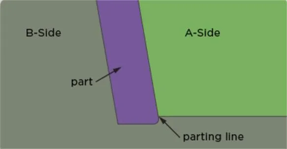
The dividing line where the parting surface intersects with the surface of the plastic part is called the parting line, which is called Parting Line in English. Therefore, the parting surface is generally referred to as the PL surface in the industry. Since the contact between the molding modules cannot be without gaps, after the plastic parts are molded, this gap is copied to the plastic parts to form a residual glue trace similar to a batch edge.
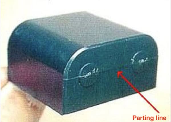
Because it looks like a line, it is called parting. Line, also called clamp line. If the parting surface is mainly discussed for the mold, then the parting line is the reflection of the parting surface on the plastic part. The thickness of the parting line will affect the appearance and function of the plastic part. Therefore, special attention needs to be paid to the structural design of plastic parts.
How is the Parting Surface (Line) Formed?
The parting line is used to get the plastic part out of the mold or to meet the molding needs of putting inserts and venting. According to the structure of the plastic part, the part of the mold that directly forms the plastic part is divided into several parts. of contact surface.
The parting line is formed as a result of the injection molding process itself, not any error. Typically, the molds that mold machinists use to produce injection molded parts are divided into two halves (called a fixed half and a moving half). When the machinist closes the mold body, the mold half (called the core plate) and the cavity surface create a parting line between the two halves of the part.

In most cases, the parting line of a molded product is perpendicular to the direction of the opening of the mold used to manufacture the product. When the machinist opens the mold and removes the cooled and solidified part, the moving half of the mold moves and separates from the stationary half (which is stationary). However, machinists sometimes separate the structure of the mold multiple times in all directions. This process is called multi-step separation.
Type of Parting Surface (Line)
Parting Surface Type
We generally call the parting surface at the largest contour of the plastic part the main parting surface, and the others are auxiliary parting surfaces.
Plane Parting Surface
The plane parting surface is relatively common and simple. It is a plane perpendicular to the direction of mold opening, as shown in the figure below.

Step Parting Surface
In some cases, the parting line of a molded product is not perpendicular to the direction of the mold opening used to make the product. When the machinist opens the mold and removes the cooled and solidified part, the moving half of the mold moves and separates from the stationary half (which is stationary). However, machinists sometimes separate the structure of the mold multiple times in all directions. This process is called multi-step separation.

When setting up the mold, arrange the two mold cavities symmetrically, as shown in the figure below. Balance the injection force on both sides of the mold and make the mold structure compact.

If the step height of the stepped parting line is too large, consider designing a cushion position and making a partially stepped parting line.

Some parts have many stepped surfaces. If the parting surface is designed following the stepped shape, the parting surface becomes complicated. In order to simplify the parting surface, consider making the parting surface a flat surface. The disadvantage is that there will be clipping lines on the appearance surface of the part. Therefore, this type of parting method is mostly used in internal components.

Inclined Parting Surface
The parting surface of the molding part is a bevel, and a sealing surface is made along the bevel (the purpose is to save mold), and then it is flattened (the purpose is to facilitate processing, positioning and counting), as shown in the figure.

Surface Parting Surface
Similar to the slope parting surface, first make a section of the sealing surface and then level it, as shown in the picture.

However, not every slope parting surface has to extend along the curved surface. For example, in the plastic part shown below, if it is extended, a sharp corner will be formed. The front mold is made of sharp steel. In this case, the slope parting surface can be directly extended.

Comprehensive Parting Surface
This form is based on the needs of the plastic part structure. Sometimes the straight and curved parting surfaces are combined, or the inclined surface and the curved parting surface are combined to form a comprehensive parting surface, as shown in the figure below.

For the comprehensive parting surface, special attention needs to be paid to the smoothing of the sealing surface at the corners of the two parting surfaces to avoid the formation of sharp points. Surface sealing should be selected. This will not only increase the strength of the mold, but also the plastic parts. It is not easy to run away from the front edge. At the same time, the smoothing treatment can reduce the occurrence of steps and sharp corners to improve the parting surface processing technology. It can be directly NC processed to reduce EDM processing.

Type of Parting Line
The type of parting line used in injection molding often depends on the specific function and structure of the plastic part. However, there are five main types: vertical, stepped, sloped, curved, and one-piece parting lines.
Vertical Parting Line

Vertical parting is the most popular of all parting lines in plastic designs. The machinist forms a vertical parting line in a direction perpendicular to the direction of mold opening.
Oblique Parting Line

Here, machinists build molds to create curved parting lines.
Step Parting Line
Here, machinists shape plastic parting lines into steps. With this type of parting line, one side of the cavity is typically subject to significant forces. This results in a relative likelihood of slippage between the fixed and moving halves of the mold.
This force can then be counteracted by creating injection forces on both sides of the cavity. The force generated may also be too large or too small. If the force is too small, the machinist will use a guide pin to compensate. Here, the impact of smaller unbalanced injection forces on the final product may not be significant.
However, if the force is too great, several solutions can be applied. Here are some examples:

Make a wedge-shaped insert on one side of the cavity. This way, the insert will relieve some of the injection force. Therefore, the mold can maintain the relative position between the cavity and the core.
Arrange the mold in a symmetrical shape. This helps to balance the injection force applied to both sides. The structure of the mold should also be as compact as possible to support.
Comprehensive PartingLine
As the name suggests, this is one of the most elaborate parting lines in plastic design. Machinists and designers work on this parting line based on the structure of the plastic part. They can combine all other parting lines to create a comprehensive plastic parting line.
Parting Surface Design Principles
Meet the Demoulding Requirements
The location of the main parting surface should be selected at the maximum contour of the projected section of the part in the demoulding direction. This is a basic principle. Under this principle, the mold structure will be simplified, otherwise it will increase the complexity of the mold structure, such as the need to add sliders and other mechanisms.

Conducive to the Smooth Removal of Plastic Parts From the Mold.
Since the ejection device of the injection molding machine is on the side of the movable mold, the parting surface should be selected to keep the plastic part on the side of the movable mold as much as possible after opening the mold. This will help the ejection mechanism set in the movable mold part to work; If an ejection mechanism is installed in the fixed mold, it will increase the complexity of the mold.

Ensure the Dimensional Accuracy and Surface Quality of the Plastic Parts
For plastic parts with high coaxiality requirements, when selecting the parting surface, it is best to place the parts with coaxiality requirements on the same side of the mold. As shown in the figure below, the stepped hole in the middle requires high coaxiality.
On the parting surface of the original design, the stepped hole is formed by the two cores of the front and rear molds respectively. After the front and rear molds are closed, the coaxiality accuracy of the two cores is It is not easy to guarantee; after the optimized parting surface and step hole are formed with a core, it is easy to guarantee the precision of processing.

When choosing where to split the mold, you need to make sure that the plastic parts will be the right size and have a good surface finish.
If you have a plastic part that needs to be really round, you should put all the parts that need to be round on the same side of the mold. In the picture below, the hole in the middle needs to be really round.
In the original design, the hole was made by two different pieces of the mold. When you close the mold, it’s hard to make sure that the two pieces of the mold are lined up perfectly. When you make the mold with just one piece, it’s easy to make sure that the hole is round.

Similarly, if you have a plastic part that needs to be really round on the outside, you should put all the parts that need to be round on the same side of the mold. In the picture below, the part that needs to be round is the plastic coupling. In the original design, the two halves of the mold were made separately. When you close the mold, it’s hard to make sure that the two halves of the mold are lined up perfectly. When you make the mold with just one piece, it’s easy to make sure that the part is round.

The size of the part that’s related to the way the mold opens and closes is affected by how the parting surface moves when you inject the plastic. In the picture, the size of the part in the original design, L, is hard to make sure is right; the size of the part in the new design doesn’t have anything to do with the parting surface, so it’s easy to make sure is right.

If you have a plastic part that needs to look good, you need to think about where the mold closes and how that will affect how the part looks.

When choosing where to split the mold, you need to think about how easy it will be to make the mold.
Usually, when you’re designing the mold, the simpler the parting surface is, the easier it is to make the mold, and the more likely it is that the mold will be right.
In the picture below, the parting surface in the original design is at a little round corner. The parting surface at a little round corner is hard to make, and it’s hard to make the mold right. In the new design, you should take the little round corners off the parting surface.

If you have multiple pillow positions on the same side, you can think about combining them into one big pillow position. This will make the parting surface structure simpler and easier to process.
If you have multiple pillow positions on the same side, you can think about combining them into one big pillow position. This will make the parting surface structure simpler and easier to process.

The Parting Surface Selection Should be Conducive to Exhaust
To ensure good exhaust conditions for the mold cavity, the parting surface should be set as far as possible at the end of the plastic melt flow direction.
In the picture below, the original parting surface design is used. When the plastic melt fills the cavity, the fractal surface is sealed first, so that the gas deep in the cavity is not easily discharged (and the parting surface has a bend, which makes it difficult for the mold to be discharged. gas); the optimized parting surface is designed at the end of the melt flow to form good exhaust conditions.

To make sure the mold cavity has good exhaust, you want to put the parting line at the end of where the plastic is going to flow. In the picture below, the original parting line design is used. When the plastic flows into the cavity, it seals off the parting line first, so the gas deep in the cavity can’t get out (and the parting line has a bend in it, which makes it hard for the mold to get the gas out); the optimized parting line is designed at the end of the flow of the plastic to make sure the gas can get out.

The Selection of Parting Surface Should Consider Simplifying the Mold Structure
If the accuracy of the side structure is not high, try to avoid the lateral core pulling (slider) mechanism, simplify the mold structure, and reduce the size of the mold, which can reduce the mold cost to a certain extent.

If you can’t avoid using a side core-pull (slider) mechanism, then when selecting the parting line, you should consider the shortest distance for the side core-pull to reduce the size of the mold; at the same time, you should make sure that the large core is in the direction of mold opening, because the clamping force is very large, and if it is placed on the side mechanism of the mold, it is not conducive to demolding.

While most of the selection and design of the above parting surfaces are actually started in the mold design stage, as structural engineers, we must have a general direction consideration in the structural design stage, especially for some parts that are easier to determine.
For profile parts, if we consider the impact of the parting surface on the structure (size progress, fit clearance, appearance quality, etc.) during structural design, then subsequent mold DFM will not lead to frequent changes. After the mold trial, There won’t be that many problems that are inherently avoidable.
Of course, the factors that affect the selection of parting surfaces are not limited to the ones listed above, and there may be other factors. Each parting surface solution is not perfect and will have advantages and disadvantages. What we need to do is to adapt to the requirements of the actual parts. Just make your selection and ensure it meets your current part requirements.

Designing parting lines for injection molded products is the best place to learn about them. Sometimes the choice is obvious, and sometimes it’s not. This section talks about why parting lines are important in plastic design.
Parting Line Design Considerations
The first thing to think about is which way the mold opens relative to the part. Mechanics call this the “draw line.” It’s important because it affects how the part looks. It also helps you know what to add to the part. Among other things, it helps you know how the marks left by the two halves of the injection molded part will look on the final part.
Another thing to think about when you’re deciding where to put the parting line is where to put the features on the part. This is because the plastic shrinks as it cools, and that can move the part in the mold. That can mess up how the part works and make it not work. Also, you don’t want the shrinkage part to shrink too much or it will be hard to get the part out of the mold.

To keep your parts in the right place, keep the walls of your injection molded part away from the parting line. The more drafts you have, the less likely the feature will break.
Another good way to figure out where your part lines should be is to look at your product’s design for manufacturability (DfM). In addition to telling you where your part lines should be, it also helps you find defects and make your parts better for manufacturing. This will help you find cheaper ways to make your parts.
Conclusion
It’s important to think about all of these part-line things when you design your injection molded products, but that’s not all. There are a bunch of important injection molding guidelines and rules that you have to follow before your injection molding process can work.

That’s why you should let Zetar Mold do your injection molding process. We have a bunch of engineers who can help you with your part design and manufacturing. With us, you can make your custom product or design in no time.
Talk to our engineers today to get the best injection molding services!


