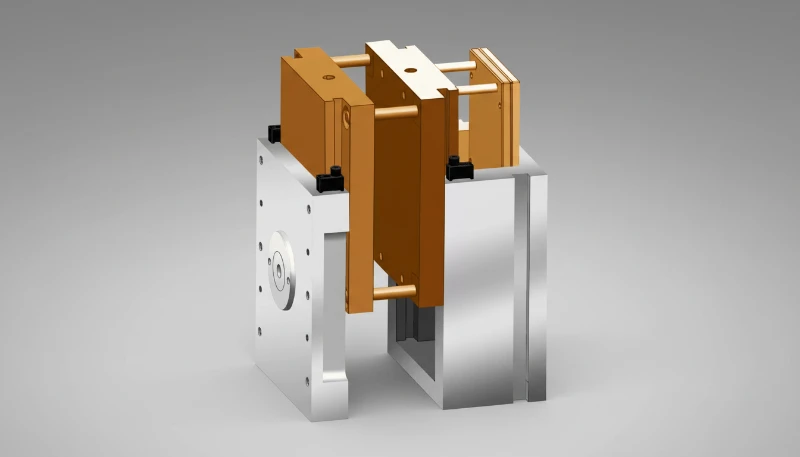
El diseño de nervaduras es una de esas competencias fundamentales que distinguen a los ingenieros de plásticos experimentados de los principiantes. He visto innumerables proyectos descarrilar por nervaduras demasiado gruesas, demasiado altas o ubicadas en lugares totalmente incorrectos. Tras dos décadas resolviendo problemas de marcas de hundimiento1, piezas deformadas y fallos de expulsión, puedo afirmar que unas nervaduras correctas determinan el éxito o el fracaso del diseño de un producto de plástico. ¿La buena noticia? Una vez comprendidas las reglas y proporciones fundamentales, diseñar nervaduras eficaces se vuelve algo natural. A continuación explicaré los principios de ingeniería y las directrices prácticas que le ahorrarán tiempo, material y muchos quebraderos de cabeza.
- Mantenga el grosor de la nervadura entre el 40-60% del grosor nominal de la pared para evitar marcas de hundimiento y huecos internos
- Limite la altura de la nervadura a un máximo de 3 veces el grosor de la nervadura, siendo 2-2.5x lo óptimo para la mayoría de aplicaciones
- Aplique un ángulo de desmoldeo mínimo de 0.5° por lado, pero se recomienda encarecidamente 1-2° para herramientas de producción
- Espacie nervaduras paralelas al menos a 2x el espesor de la pared, siendo un espaciado de 3-4x ideal para la fabricabilidad
- Utilice múltiples nervaduras más cortas en lugar de menos nervaduras altas para distribuir la tensión y mejorar la moldeabilidad
¿Qué es una nervadura en el diseño de productos plásticos?
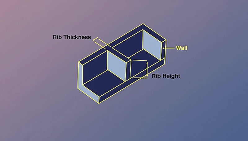
Una nervadura es una pared fina y saliente diseñada para aumentar la rigidez estructural sin añadir una cantidad significativa de material o peso a una pieza de plástico. Piense en las nervaduras como la columna vertebral del diseño: son refuerzos estratégicos que aumentan el momento de inercia2 y evitan la flexión en zonas críticas. En el moldeo por inyección, las nervaduras aparecen como elementos elevados en un lado de la pieza y se extienden perpendicularmente o en ángulo desde la superficie de la pared principal.
Desde un punto de vista de ingeniería, las nervaduras funcionan alejando el material del eje neutro de flexión. Esto aumenta el momento de inercia de la sección transversal, que se correlaciona directamente con la rigidez. Una nervadura bien colocada puede aumentar la rigidez local en un 300-500% mientras añade solo un 10-15% más de material en comparación con simplemente engrosar toda la pared.
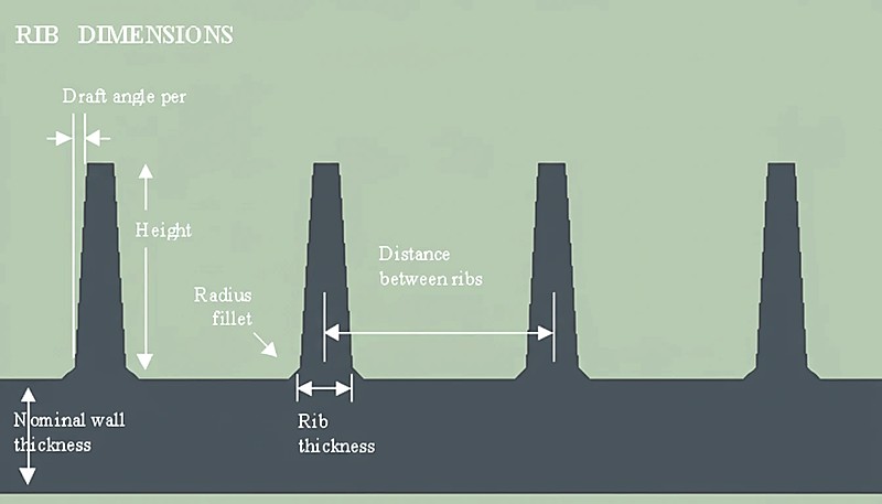
Características principales de las nervaduras moldeadas por inyección: Espesor de la base: 40–60% del espesor nominal de pared. Altura: normalmente entre 2 y 3 veces el espesor de la nervadura. Ángulo de desmoldeo3: mínimo de 0.5° por lado, preferiblemente de 1° a 2°. Radio de acuerdo: de 0.2 a 0.5 mm en la unión con la base.
Las nervaduras pueden correr en líneas rectas, seguir curvas o crear patrones de cuadrícula complejos según sus requisitos estructurales. Las aplicaciones más comunes incluyen rigidizar grandes superficies planas, reforzar soportes de montaje, crear bisagras vivas y reemplazar secciones de pared gruesas en diseños sensibles al costo. Comprender cómo dimensionar y ubicar correctamente estas características es esencial para cualquier ingeniero que trabaje con productos plásticos.
¿Por qué los productos de plástico necesitan nervaduras?
Las nervaduras son refuerzos estructurales que añaden rigidez a las piezas de plástico sin aumentar el grosor de la pared. Los plásticos de ingeniería tienen un módulo 50–200 veces menor que los metales (1–4 GPa frente a 200 GPa), por lo que las piezas se deforman mucho más bajo carga. Las nervaduras resuelven esto aumentando el momento de inercia donde más importa, usando material extra mínimo y manteniendo tiempos de ciclo cortos.
Los cuatro factores principales para el nervado son:
Eficiencia del material: Un diseño con nervaduras puede ofrecer una rigidez equivalente utilizando entre un 20 y un 40% menos de material que una pared de grosor uniforme. En la producción de gran volumen, esto supone un ahorro considerable. Por ejemplo, sustituir una pared de 4 mm por una de 2 mm con nervaduras optimizadas puede reducir el consumo de material en un 35% y mantener la misma resistencia a la flexión.
Reducción del tiempo de ciclo: Las paredes gruesas se enfrían lentamente y crean cuellos de botella en la producción. El tiempo de enfriamiento sigue el cuadrado del espesor de pared: duplicar el espesor cuadruplica el tiempo de enfriamiento. Al utilizar nervaduras en lugar de secciones gruesas, a menudo puede reducirse el tiempo de ciclo entre un 15 y un 25%, mejorando directamente la productividad.
Estabilidad dimensional: Las secciones gruesas se contraen de manera desigual durante el enfriamiento, lo que provoca deformaciones, marcas de hundimiento y tensiones internas. Las nervaduras permiten mantener el rendimiento estructural con secciones de pared finas y uniformes, lo que mejora el control dimensional y la calidad superficial.
Flexibilidad de diseño: Las nervaduras permiten ajustar la rigidez exactamente donde se necesita. En lugar de sobredimensionar toda la pieza, pueden colocarse refuerzos estratégicamente en las zonas sometidas a grandes esfuerzos y mantener finas y ligeras las regiones con poca carga.
He trabajado en proyectos donde un nervado adecuado redujo el peso de la pieza en un 30% mientras mejoraba la rigidez en un 200%. La clave es entender que las nervaduras no son solo características de ahorro de costos: son herramientas de ingeniería sofisticadas que permiten un mejor rendimiento general del diseño. En nuestra fábrica, validamos los cambios en las nervaduras con una revisión de flujo de molde y medición del primer disparo antes de aprobar la herramienta de producción.
¿Cuáles son las pautas clave de diseño de nervaduras?
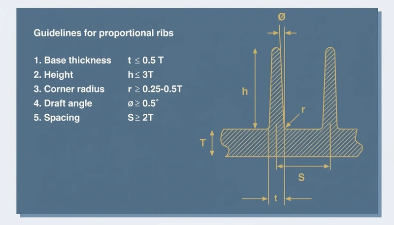
Las pautas clave de diseño de nervaduras son la relación de espesor, los límites de altura, el ángulo de desmoldeo, el radio de filete y el espaciado. Cada uno debe equilibrar la resistencia estructural con la moldeabilidad — equivocarse en uno puede causar marcas de hundimiento, alabeo o fallos de expulsión.
Relación de espesores (regla del 40–60%): El espesor de la nervadura debe equivaler al 40–60% del espesor nominal de pared. Esta relación evita las marcas de hundimiento y conserva una resistencia adecuada. Para una pared de 2 mm, la nervadura debe tener entre 0.8 y 1.2 mm de espesor. El porcentaje exacto depende del material y de los requisitos estéticos: las piezas estéticas utilizan un 40–50% para minimizar las marcas de hundimiento; las piezas estructurales utilizan un 50–60% para obtener la máxima resistencia; los materiales semicristalinos deben mantenerse cerca del 40% debido a su mayor contracción; los materiales amorfos pueden acercarse al 60% con menor riesgo.
Directrices de altura: La altura de una nervadura no debe superar 3 veces su espesor; el intervalo óptimo es de 2 a 2.5 veces. Una nervadura de 1 mm de espesor no debe medir más de 3 mm de altura y, preferiblemente, entre 2 y 2.5 mm. Por encima de esta relación, las nervaduras resultan difíciles de llenar y pueden pandearse bajo carga. El beneficio de rigidez sigue una relación cúbica con la altura, por lo que duplicar la altura multiplica la rigidez por 8, pero solo si la nervadura puede moldearse correctamente y no falla por compresión.
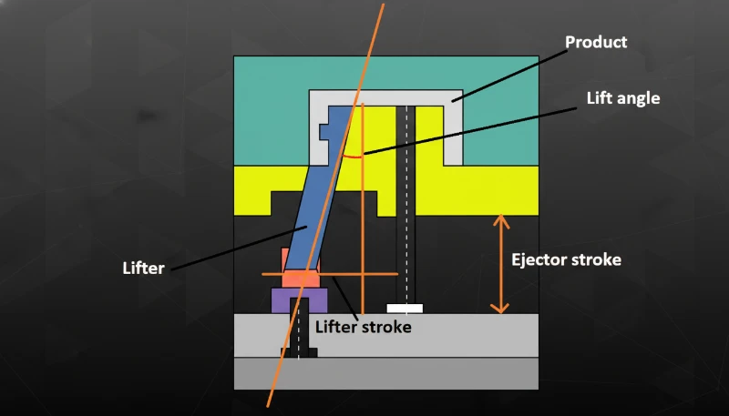
Requisitos del ángulo de desmoldeo: Se exige un mínimo de 0.5° por lado, aunque para moldes de producción se recomienda encarecidamente entre 1° y 2°. Las nervaduras profundas necesitan al menos 1° por lado. Si la cavidad del molde tendrá textura, añada 1° adicional por lado. Ángulo de desmoldeo = 0.5° + 0.035° × (altura en mm) es una buena fórmula inicial para superficies lisas.
Radio de acuerdo: Incluya siempre un radio pequeño (0.2–0.5 mm) donde la nervadura se une a la pared base. Las esquinas agudas generan concentraciones de tensión y son difíciles de mecanizar en el molde. El radio también favorece el flujo del material durante la inyección.
Consideraciones de separación: Las nervaduras paralelas deben estar separadas al menos 2 veces el espesor de pared; lo ideal es entre 3 y 4 veces. Una separación menor crea secciones gruesas entre las nervaduras y anula sus ventajas. Para una pared de 2 mm, separe las nervaduras al menos 4 mm y, preferiblemente, entre 6 y 8 mm.
¿Cómo se determina el espesor correcto de la nervadura?
El grosor correcto de la nervadura es del 40–60% del grosor nominal de la pared, dependiendo del material, la estética y las demandas estructurales. La regla estándar del 40-60% proporciona un punto de partida, pero las propiedades del material, la geometría de la pieza y los requisitos de calidad influyen en la decisión final.
Comience por clasificar el material: Los materiales amorfos (ABS, PC, PVC) se contraen entre un 0.3 y un 0.7% y pueden admitir espesores de nervadura de hasta el 60% del espesor de pared sin marcas de hundimiento graves. Los materiales semicristalinos (PE, PP, POM, nailon) se contraen entre un 1.5 y un 3% y deben mantenerse cerca del 40–50% para evitar defectos superficiales.
Calcule el espesor máximo permitido: Para superficies visibles, utilice esta fórmula: espesor máximo de la nervadura = 0.4 × espesor de pared en el diseño inicial. Para superficies ocultas o texturizadas en las que las marcas de hundimiento sean menos críticas, puede llegar a 0.6 × el espesor de pared.
Considere la función de la pieza: Los componentes estructurales pueden utilizar nervaduras más gruesas (intervalo del 55–60%) porque el aspecto es secundario frente al rendimiento. Las carcasas estéticas deben mantenerse en el intervalo del 40–45% para conservar la calidad superficial. Si la pieza va a pintarse o texturizarse, pueden aceptarse ligeras marcas de hundimiento, lo que permite utilizar el extremo superior del intervalo de espesores.
Tenga en cuenta la variación del espesor de pared: Las piezas reales moldeadas por inyección presentan una variación de espesor de ±0.05–0.15 mm según el control del proceso. Cuando la pared base resulta más gruesa, la nervadura representa un porcentaje mayor del espesor real, lo que aumenta el riesgo de marcas de hundimiento. Recomiendo diseñar las nervaduras a partir del espesor nominal de pared menos una desviación estándar para tener en cuenta esta variación.
Valide mediante análisis Moldflow: En aplicaciones críticas, realice un análisis Moldflow para predecir la gravedad de las marcas de hundimiento. El software puede modelar los patrones de enfriamiento y predecir dónde aparecerán defectos superficiales. Esto resulta especialmente útil en patrones complejos de nervaduras, donde los cálculos manuales se vuelven difíciles.
Un enfoque práctico que utilizo: empiece con un 45% para diseños nuevos y ajuste después según los resultados del prototipo. Si aparecen rechupes, reduzca en incrementos de 0.05-0.1mm. Si el rendimiento estructural es insuficiente, aumente el espesor o añada más nervaduras en lugar de superar el 60% del espesor de pared.
¿Cuál es la relación entre la altura de la nervadura y la resistencia estructural?
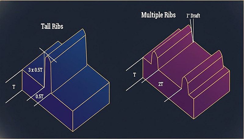
La altura de las nervaduras y la resistencia estructural están relacionadas por la ley de la potencia cúbica: duplicar la altura proporciona aproximadamente 8× más rigidez. Esto solo se cumple si la nervadura permanece estable y se llena correctamente durante el moldeo, por lo que optimizar la altura es esencial para lograr un diseño eficiente.
Explicación de la relación cúbica: La rigidez aumenta con el cubo de la distancia al eje neutro. Al duplicar la altura de una nervadura, el material se aleja del eje central de flexión, lo que produce un aumento drástico de la rigidez. Sin embargo, este beneficio teórico presupone que la nervadura conserva toda su sección transversal y no se pandea ni falla por compresión.
Limitaciones prácticas de altura: Aunque las nervaduras más altas proporcionan mayor rigidez, las restricciones de fabricación limitan la altura práctica a 3 veces el espesor de la nervadura. Por encima de esta relación surgen varios problemas: llenado incompleto durante el procesamiento del molde de inyección, mayor tendencia al pandeo bajo cargas de compresión, dificultad para lograr ángulos de desmoldeo adecuados y problemas de expulsión del molde.
Ventaja de usar varias nervaduras: Emplear varias nervaduras más cortas suele ofrecer mejores resultados que usar menos nervaduras altas, tanto por razones estructurales como de fabricación. Tres nervaduras de 2 mm de altura distribuyen la tensión de manera más uniforme que una de 6 mm, aunque el consumo de material sea similar. Las nervaduras cortas son más fáciles de moldear, menos propensas al pandeo y causan menos problemas de marcas de hundimiento.
Relaciones óptimas entre altura y espesor según la aplicación: Las piezas estéticas utilizan una relación 2:1 para minimizar las marcas de hundimiento. Las piezas estructurales generales emplean una relación 2.5:1 para equilibrar el rendimiento. Las aplicaciones de alta resistencia pueden alcanzar una relación máxima permitida de 3:1. Las piezas de embutición profunda utilizan una relación de 1.5–2:1 debido a los problemas de expulsión.
Estrategias de distribución de alturas: En condiciones de carga complejas, varíe la altura de las nervaduras según las necesidades locales de tensión. Utilice nervaduras más altas en zonas sometidas a grandes esfuerzos y otras más cortas como refuerzo general. Este enfoque optimiza la distribución del material y mantiene la viabilidad de fabricación. Recuerde siempre que la eficacia de una nervadura depende del sistema completo: altura, espesor, separación y orientación deben funcionar conjuntamente para alcanzar los objetivos estructurales.
¿Cómo afecta la ubicación de la nervadura al rendimiento de la pieza?
La ubicación de los nervios es el principal factor de distribución de cargas: una colocación correcta aumenta la rigidez un 300-500%. Una ubicación deficiente desperdicia material, alarga el ciclo y puede aportar un beneficio estructural mínimo.
Principios de colocación estratégica: Coloque las nervaduras perpendiculares a la dirección principal de la tensión para lograr la máxima eficacia. Si la pieza soporta cargas de flexión, sitúe las nervaduras paralelas al eje neutro de flexión. Para cargas de torsión, utilice nervaduras diagonales o dispuestas en patrones cruzados. La clave es comprender las condiciones de carga mediante análisis de tensiones o ensayos.
Patrones escalonados frente a uniformes: Los patrones de nervaduras escalonados suelen superar a la separación uniforme porque distribuyen la tensión de forma más homogénea y reducen el riesgo de propagación de grietas a lo largo de líneas paralelas. En lugar de colocar sistemáticamente nervaduras cada 10 mm, varíe la separación entre 8 y 12 mm para romper los patrones de concentración de tensiones. Este enfoque también mejora la resistencia al pandeo bajo cargas de compresión.
Cómo evitar concentradores de tensión: Nunca termine bruscamente una nervadura en medio de una pared, pues esto crea puntos de concentración de tensiones que pueden iniciar grietas. Reduzca gradualmente la altura de la nervadura hasta cero a lo largo de una distancia equivalente a 2–3 veces su altura. En las intersecciones donde las nervaduras se unen con otros elementos, mantenga transiciones suaves con radios de acuerdo adecuados.
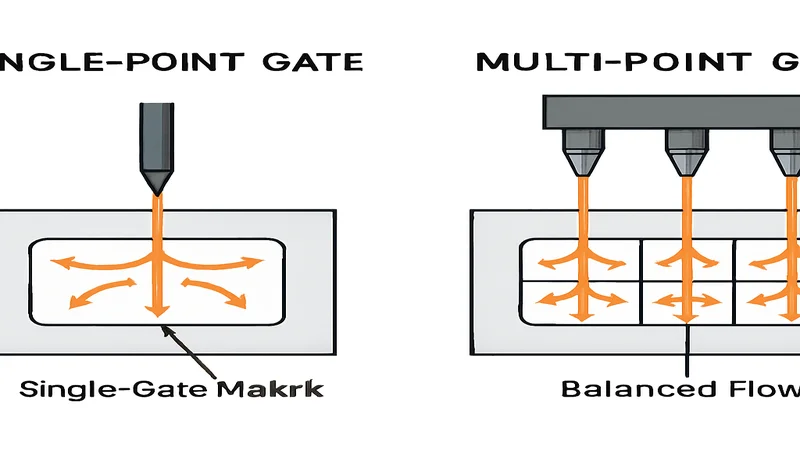
Consideraciones sobre el flujo del material: La colocación de las nervaduras afecta al flujo del plástico durante el moldeo por inyección. Las nervaduras perpendiculares a la dirección del flujo pueden crear líneas de soldadura y aire atrapado, mientras que las alineadas con el flujo ayudan a guiar el material y mejoran el llenado. Tenga en cuenta la ubicación de la compuerta al colocar las nervaduras: sitúe las nervaduras estructurales críticas en zonas que se llenen al principio del ciclo de moldeo.
Integración del montaje y la fijación: Utilice nervaduras para reforzar puntos de montaje, elementos de encaje a presión e interfaces de ensamblaje donde se concentran las cargas. Un error habitual es diseñar resaltes de montaje sin un soporte adecuado de nervaduras, lo que provoca grietas por tensión alrededor de los elementos de fijación. Rodee los elementos de montaje con nervaduras que distribuyan las cargas hacia la estructura principal.
¿Cuáles son los errores comunes de diseño de nervaduras que se deben evitar?
Los errores más comunes al diseñar nervaduras incluyen ignorar las relaciones de espesor, aplicar ángulos de desmoldeo insuficientes y comprender mal el comportamiento del material. Estos errores provocan sistemáticamente problemas de producción y calidad, además de costosas revisiones del diseño.
Espesor excesivo de las nervaduras: Las nervaduras que superan el 60% del espesor de pared provocan marcas de hundimiento visibles en superficies estéticas y huecos internos en piezas estructurales. El material se acumula en la unión entre la nervadura y la pared y se enfría de forma desigual.
Ángulo de desmoldeo insuficiente: Un ángulo mínimo o nulo provoca problemas de expulsión, raspa las superficies de las nervaduras y daña el molde. La mayoría de las nervaduras de producción necesitan al menos 1° por lado, y las nervaduras profundas requieren 1.5° o más para desmoldearse limpiamente.
No tener en cuenta la contracción del material: Los materiales semicristalinos, como el nailon y el POM, se contraen entre un 1.5 y un 3%, mientras que las resinas amorfas, como ABS y PC, solo se contraen entre un 0.3 y un 0.7%. Diseñar nervaduras sin tener en cuenta esta diferencia provoca fallos dimensionales y problemas de montaje.
Terminación deficiente de las nervaduras: Terminar bruscamente las nervaduras crea concentraciones de tensión que inician grietas. Reduzca siempre las nervaduras de forma gradual o conéctelas a otros elementos estructurales. Las transiciones bruscas son puntos débiles de fabricación que provocarán fallos durante el uso.
Nervaduras enfrentadas en ambos lados: Colocar nervaduras directamente opuestas duplica el espesor efectivo de pared, lo que provoca graves marcas de hundimiento y prolonga el tiempo de enfriamiento. Desplace siempre las nervaduras opuestas al menos una anchura de nervadura para evitar este problema.
Separación insuficiente: Las nervaduras demasiado próximas crean secciones gruesas que provocan marcas de hundimiento y prolongan el tiempo de ciclo. Mantenga entre nervaduras paralelas una separación mínima de 2 veces el espesor de pared; lo ideal para la mayoría de las aplicaciones es entre 3 y 4 veces.
En nuestra fábrica de Shanghái hemos procesado más de 400+ materiales en 47 máquinas de moldeo por inyección de entre 90T y 1850T. Nuestros 8 ingenieros sénior revisan el diseño de cada nervio durante el análisis DFM para detectar problemas de espesor, ángulos de desmoldeo y riesgos de rechupes antes de cortar el acero. Tras 20+ años de experiencia en moldeo por inyección y fabricación de moldes, hemos comprobado directamente cómo una reducción del 10% en el espesor de los nervios puede eliminar por completo los rechupes y salvar una serie de producción.
¿Cómo influyen las propiedades del material en el diseño de nervaduras?
Las propiedades del material son los principales factores del diseño de nervios: la contracción, el módulo y la cristalinidad determinan los parámetros. Comprender estos fundamentos evita costosas revisiones del utillaje y fallos de producción.
Comportamiento amorfo frente a semicristalino: Los materiales amorfos (ABS, PC, PMMA) se contraen uniformemente entre un 0,3 y un 0,7 % y admiten nervaduras con un espesor de hasta el 60 % del espesor de pared. Su contracción predecible ofrece más margen en el diseño de nervaduras. Los materiales semicristalinos (PE, PP, POM, nailon) se contraen entre un 1,5 y un 3 % siguiendo patrones menos predecibles, por lo que requieren un espesor de nervadura conservador, como máximo del 40-50 %.
Consideraciones sobre el módulo: Los materiales de alto módulo, como los nailones reforzados con fibra de vidrio (8-15 GPa), pueden no necesitar nervaduras pronunciadas, ya que el material base aporta una rigidez considerable. Los materiales de bajo módulo, como el polietileno (0,2-0,4 GPa), requieren abundantes nervaduras en aplicaciones estructurales. El retorno de la inversión en nervaduras disminuye a medida que aumenta el módulo del material base.
Proporciones de nervadura según la contracción: En ABS y PC puede utilizarse hasta el 60 % del espesor de pared. En PP y PE no debe superarse el 45-50 %. Para POM y nailon se recomienda un 40-45 %. Los materiales reforzados con fibra de vidrio requieren una reducción del 5-10 % debido a la contracción anisotrópica.
"Por lo general, es mejor utilizar más nervaduras cortas que menos nervaduras altas."True
Varias nervaduras más cortas distribuyen la tensión de manera más uniforme y reducen el riesgo de rechupes y alabeo frente a nervaduras altas y gruesas.
"El espesor de la nervadura debe ser igual al espesor nominal de pared para obtener la máxima resistencia."False
Los nervios deben tener el 40-60% del espesor de pared. Los nervios con el espesor completo provocan rechupes, deformación y huecos internos; de hecho, debilitan la pieza.
Efecto de las características de flujo: Los materiales de alta fluidez llenan más fácilmente las nervaduras finas, lo que permite utilizar el extremo inferior de las proporciones de espesor sin perder la resistencia necesaria. Los materiales de baja fluidez o alta viscosidad pueden requerir nervaduras algo más gruesas para garantizar el llenado completo, pero esto debe equilibrarse con el riesgo de marcas de hundimiento.
Colaboración con su proveedor: La elección del material influye notablemente en la viabilidad y el coste del diseño de nervaduras. Cuando trabaje con un proveedor de moldeo por inyección, consulte durante la fase de diseño las pautas de nervaduras específicas del material. Los proveedores experimentados pueden ofrecer recomendaciones basadas en su experiencia de procesamiento y ayudar a optimizar las nervaduras tanto para el rendimiento como para la fabricabilidad.
Consideraciones de temperatura: Los materiales para altas temperaturas pueden requerir diseños de nervadura diferentes debido a la expansión térmica y al comportamiento de fluencia. Los materiales utilizados por encima de su temperatura de transición vítrea necesitan una separación y un espesor de nervaduras más conservadores para conservar la estabilidad dimensional a largo plazo.
Comprender estas verdades fundamentales sobre el comportamiento de los nervios ayuda a evitar los errores de diseño más habituales. La diferencia entre las directrices teóricas y la realidad productiva es donde la mayoría de los proyectos encuentra problemas. En la práctica, la selección del material, la ubicación de los puntos de inyección y el diseño de los canales de enfriamiento interactúan con la geometría de los nervios de formas que unas simples reglas prácticas no pueden reflejar por completo. Por eso, los ingenieros de utillaje experimentados siempre validan los diseños de nervios mediante simulación de flujo antes de cortar el acero. El coste de detectar problemas durante la simulación equivale aproximadamente al uno por ciento del coste de rectificar un molde terminado.
"Los nervios pueden sustituir secciones de pared gruesas para reducir el uso de material y mantener la rigidez."True
Esta es la finalidad principal de los nervios. Un patrón de nervios bien diseñado puede lograr una rigidez equivalente con un 20-40% menos de material que una pared gruesa uniforme.
"Un ángulo de desmoldeo de 0.5° es suficiente para todos los diseños de nervaduras."False
Aunque 0.5° es el mínimo absoluto, la mayoría de las aplicaciones se benefician de un ángulo de desmoldeo de 1°-2°. Las nervaduras profundas o las superficies texturizadas pueden requerir aún más ángulo para garantizar una expulsión limpia.
Preguntas frecuentes: ¿Cuáles son las preguntas más comunes sobre el diseño de nervaduras?
¿Cuál es la proporción recomendada del espesor de los nervios para el moldeo por inyección?
La recomendación estándar es el 40-60% del espesor nominal de la pared. Para piezas estéticas en las que los rechupes sean críticos, manténgase en el 40% o menos. Para piezas estructurales en las que el aspecto sea menos importante, puede acercarse al 60%. La proporción exacta también depende del material: los materiales amorfos como el ABS admiten nervaduras ligeramente más gruesas que los materiales semicristalinos como el nailon. Consulte siempre con su fabricante de utillajes durante la fase DFM para validar las dimensiones de las nervaduras con respecto al grado específico del material y las condiciones de producción que prevé utilizar. La interacción entre la geometría de las nervaduras, la ubicación de la compuerta y el tiempo de enfriamiento es lo bastante compleja como para que las directrices genéricas deban tratarse como puntos de partida y no como especificaciones finales.
¿Qué altura debe tener un nervio en relación con su espesor?
Normalmente, un nervio no debe superar 3 veces el espesor de su base. Por encima de esta proporción, resulta difícil llenarlo durante el moldeo y puede pandearse bajo carga. En la práctica, la mayoría de los diseños eficaces utilizan una relación altura-espesor de 2:1 a 2.5:1, equilibrando la mejora estructural y la fabricabilidad. Consulte siempre con el fabricante del molde durante la fase de DFM para validar las dimensiones del nervio respecto al grado específico del material y las condiciones de producción previstas. La interacción entre la geometría del nervio, la ubicación de la compuerta y el tiempo de enfriamiento es lo bastante compleja como para que las directrices genéricas deban considerarse puntos de partida y no especificaciones finales.
¿Qué ángulo de desmoldeo necesitan las nervaduras en el moldeo por inyección?
Los nervios necesitan un ángulo de desmoldeo mínimo de 0.5° por lado, aunque se recomienda encarecidamente entre 1° y 2° para moldes de producción. Los nervios profundos (de más de 20mm de altura) deben tener al menos 1.5° de desmoldeo. Si la superficie del molde está texturizada, añada al menos 1° adicional de desmoldeo por lado para evitar raspaduras durante la expulsión. Consulte siempre con el fabricante del molde durante la fase DFM para validar las dimensiones de los nervios respecto al grado específico del material y las condiciones de producción previstas. La interacción entre la geometría de los nervios, la ubicación de la compuerta y el tiempo de enfriamiento es lo bastante compleja como para que las directrices genéricas deban considerarse puntos de partida, no especificaciones definitivas.
¿Cómo se evitan las marcas de hundimiento cerca de las nervaduras?
Las marcas de hundimiento aparecen cuando el grosor de las nervaduras crea secciones gruesas localizadas que se enfrían de forma desigual. Para minimizarlas: mantenga el grosor de las nervaduras en un máximo del 50% del grosor de la pared, añada un radio pequeño (0.2-0.5mm) en la unión entre nervadura y pared, y considere utilizar un agente espumante o moldeo asistido por gas para piezas de paredes gruesas. Acercar la entrada a la zona de la nervadura también puede ayudar a mantener la presión de compactación. Consulte siempre al fabricante del utillaje durante la fase de DFM para validar las dimensiones de las nervaduras respecto al grado específico del material y las condiciones de producción previstas. La interacción entre la geometría de la nervadura, la ubicación de la entrada y el tiempo de enfriamiento es lo bastante compleja como para que las directrices genéricas se consideren puntos de partida, no especificaciones definitivas.
¿Qué separación debe utilizarse entre nervios paralelos?
Los nervios paralelos deben estar separados al menos 2 veces el espesor de pared nominal; entre 3 y 4 veces es lo ideal para la mayoría de las aplicaciones. Una separación demasiado estrecha crea secciones gruesas entre los nervios, lo que provoca rechupes, deformación y tiempos de ciclo más largos. Los patrones de nervios alternados suelen funcionar mejor que los nervios paralelos espaciados uniformemente. Consulte siempre al fabricante del utillaje durante la fase de DFM para validar las dimensiones de los nervios según el grado de material y las condiciones de producción que vaya a utilizar. La interacción entre la geometría de los nervios, la ubicación del punto de inyección y el tiempo de enfriamiento es lo bastante compleja como para que las directrices generales se consideren puntos de partida, no especificaciones finales.
¿Se pueden utilizar nervaduras simultáneamente en ambos lados de una pared?
Sí, pero con precaución. Cuando hay nervaduras a ambos lados de una pared, deben estar desplazadas, nunca directamente enfrentadas. Las nervaduras directamente opuestas crean un espesor de pared efectivo igual a la pared más ambas nervaduras, lo que provoca rechupes graves y tiempos de enfriamiento muy prolongados. Desplace las nervaduras al menos una anchura de nervadura para evitar este problema. Consulte siempre con el fabricante del utillaje durante la fase de DFM para validar las dimensiones de las nervaduras respecto al grado específico del material y las condiciones de producción previstas. La interacción entre la geometría de las nervaduras, la ubicación del punto de inyección y el tiempo de enfriamiento es lo bastante compleja como para que las directrices genéricas deban considerarse puntos de partida y no especificaciones finales.
¿Necesita una revisión DFM experta para el diseño de sus nervaduras?
El equipo de ingeniería de ZetarMold proporciona análisis gratuitos de diseño para fabricación (DFM) en cada proyecto. Con más de 20 años de experiencia en más de 400 materiales, detectamos problemas de diseño de nervios antes de iniciar el utillaje, ahorrándole tiempo y dinero. Solicite un presupuesto gratuito y reciba comentarios de expertos en 24 horas.
marcas de hundimiento: Las marcas de hundimiento son depresiones superficiales en piezas moldeadas por inyección causadas por el enfriamiento desigual y la contracción del material en secciones gruesas, como las uniones entre nervadura y pared. ↩
momento de inercia: El momento de inercia mide la resistencia de una sección transversal a la flexión. Añadir nervaduras aumenta el momento de inercia sin incrementar de forma significativa el consumo de material. ↩
ángulo de desmoldeo: El ángulo de desmoldeo es la inclinación aplicada a las superficies verticales de una cavidad del molde para poder expulsar la pieza sin dañarla. Las nervaduras suelen necesitar un ángulo de 0,5°-2° por lado. ↩