 Skip to content

Rib design is one of those critical skills that separates experienced plastic engineers from newcomers. I’ve seen countless projects derailed by ribs that are too thick, too tall, or placed in completely wrong locations. After two decades of troubleshooting sink marks1, warped parts, and ejection failures, I can tell you that proper ribbing makes or breaks a plastic product design. The good news? Once you understand the fundamental rules and ratios, designing effective ribs becomes second nature. Let me walk you through the engineering principles and real-world guidelines that will save you time, material, and plenty of headaches.
- Keep rib thickness between 40-60% of nominal wall thickness to prevent sink marks and internal voids
- Limit rib height to 3x the rib thickness maximum, with 2-2.5x being optimal for most applications
- Apply minimum 0.5° draft angle per side, but 1-2° is strongly recommended for production tooling
- Space parallel ribs at least 2x wall thickness apart, with 3-4x spacing being ideal for manufacturability
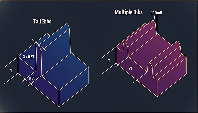
- Use multiple shorter ribs instead of fewer tall ribs to distribute stress and improve moldability
What is a rib in plastic product design?
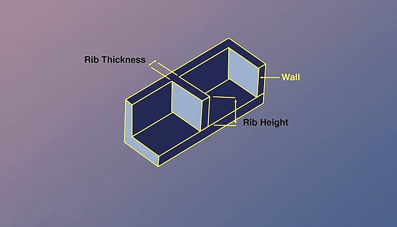
A rib is a thin, protruding wall feature designed to increase structural stiffness without adding significant material or weight to a plastic part. Think of ribs as the backbone of your design — they’re strategic reinforcements that boost the moment of inertia2 and prevent flexing in critical areas. In injection molding, ribs appear as raised features on one side of the part, extending perpendicular or at angles from the main wall surface.
From an engineering standpoint, ribs work by moving material away from the neutral axis of bending. This increases the cross-sectional moment of inertia, which directly correlates to stiffness. A well-placed rib can increase local stiffness by 300-500% while adding only 10-15% more material compared to simply thickening the entire wall.
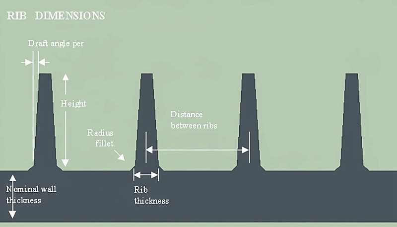
Key characteristics of injection molded ribs: Base thickness: 40–60% of nominal wall thickness. Height: typically 2–3 times the rib thickness. draft angle3: minimum 0.5° per side, preferably 1–2°. Fillet radius: 0.2–0.5 mm at the base junction.
Ribs can run in straight lines, follow curves, or create complex grid patterns depending on your structural requirements. The most common applications include stiffening large flat surfaces, reinforcing mounting bosses, creating living hinges, and replacing thick wall sections in cost-sensitive designs. Understanding how to properly size and locate these features is essential for any engineer working with plastic products.
Why do plastic products need ribs?
Ribs are structural reinforcements that add stiffness to plastic parts without increasing wall thickness. Engineering plastics have 50–200× lower modulus than metals (1–4 GPa vs 200 GPa), so parts deflect far more under load. Ribs solve this by increasing the moment of inertia where it matters most, using minimal extra material and keeping cycle times short.
The four main drivers for ribbing are:
Material efficiency: A ribbed design can deliver equivalent stiffness with 20-40% less material than a uniformly thick wall. In high-volume production, this translates to substantial cost savings. For example, replacing a 4mm thick wall with a 2mm wall plus optimized ribs can reduce material usage by 35% while maintaining the same flexural strength.
Cycle time reduction: Thick walls cool slowly and create bottlenecks in production. The cooling time follows the square of the wall thickness — doubling wall thickness quadruples cooling time. By using ribs instead of thick sections, you can often reduce cycle time by 15-25%, directly improving productivity.
Dimensional stability: Thick sections shrink unevenly during cooling, causing warpage, sink marks, and internal stresses. Ribs allow you to maintain structural performance while keeping wall sections thin and uniform, resulting in better dimensional control and surface quality.
Design flexibility: Ribs let you tune stiffness exactly where you need it. Instead of over-designing the entire part, you can strategically place reinforcement in high-stress areas while keeping low-stress regions thin and lightweight.
I have worked on projects where proper ribbing reduced part weight by 30% while improving stiffness by 200%. The key is understanding that ribs are not just cost-saving features — they are sophisticated engineering tools that enable better overall design performance. In our factory, we validate rib changes with mold-flow review and first-shot measurement before approving production tooling.
What are the key rib design guidelines?
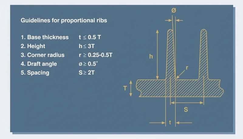
The key rib design guidelines are thickness ratio, height limits, draft angle, fillet radius, and spacing. Each must balance structural strength against moldability — getting one wrong can cause sink marks, warp, or ejection failures.
Thickness Ratio (The 40-60% Rule): Rib thickness should be 40-60% of the nominal wall thickness. This ratio prevents sink marks while maintaining adequate strength. For a 2mm wall, your rib should be 0.8-1.2mm thick. The exact percentage depends on material and appearance requirements: Cosmetic parts use 40-50% to minimize sink marks. Structural parts use 50-60% for maximum strength. Semi-crystalline materials should stay closer to 40% due to higher shrinkage. Amorphous materials can push toward 60% with less risk.
Height Guidelines:
Rib height should not exceed 3 times the rib thickness, with 2-2.5x being optimal. A 1mm thick rib should be no taller than 3mm, preferably 2-2.5mm. Beyond this ratio, ribs become difficult to fill and may buckle under load. The stiffness benefit follows a cubic relationship with height, so doubling height increases stiffness by 8x — but only if the rib can be properly molded and doesn’t fail in compression.
Draft Angle Requirements:
Minimum 0.5° per side is required, but 1-2° is strongly recommended for production tooling. Deep ribs need at least 1° per side. If your mold cavity will have texture, add an additional 1° per side. Draft angle = 0.5° + 0.035° × (height in mm) is a good starting formula for smooth surfaces.
Fillet Radius:
Always include a small radius (0.2-0.5mm) where the rib meets the base wall. Sharp corners create stress concentrations and are difficult to machine in the mold. The radius also helps with material flow during injection.
Spacing Considerations:
Parallel ribs should be spaced at least 2x wall thickness apart, with 3-4x being ideal. Closer spacing creates thick sections between ribs, negating the benefits of ribbing. For a 2mm wall thickness, space ribs at least 4mm apart, preferably 6-8mm.
How do you determine the correct rib thickness?
The correct rib thickness is 40–60% of the nominal wall thickness, depending on material, cosmetics, and structural demands. The standard 40-60% rule provides a starting point, but material properties, part geometry, and quality requirements all influence the final decision.
Start with material classification:
Amorphous materials (ABS, PC, PVC) shrink 0.3-0.7% and can tolerate rib thicknesses up to 60% of wall thickness without severe sink marks. Semi-crystalline materials (PE, PP, POM, Nylon) shrink 1.5-3% and should stay closer to 40-50% to prevent surface defects.
Calculate the maximum allowable thickness:
For visible surfaces, use this formula: Maximum rib thickness = 0.4 × wall thickness for first-pass design. For hidden or textured surfaces where sink marks are less critical, you can push to 0.6 × wall thickness.
Consider the part’s function:
Structural components can use thicker ribs (55-60% range) because appearance is secondary to performance. Cosmetic housings should stay in the 40-45% range to maintain surface quality. If the part will be painted or textured, slight sink marks may be acceptable, allowing you to use the upper end of the thickness range.
Account for wall thickness variation:
Real injection molded parts have thickness variation of ±0.05-0.15mm depending on the process control. When the base wall runs thick, your rib becomes a higher percentage of the actual thickness, increasing sink mark risk. I recommend designing ribs based on the nominal wall thickness minus one standard deviation to account for this variation.
Validate with moldflow analysis:
For critical applications, run moldflow analysis to predict sink mark severity. The software can model cooling patterns and predict where surface defects will occur. This is especially valuable for complex rib patterns where manual calculations become difficult.
A practical approach I use: Start at 45% for new designs, then adjust based on prototype results. If sink marks appear, reduce by 0.05-0.1mm increments. If structural performance is insufficient, increase thickness or add more ribs rather than exceeding 60% of wall thickness.
What is the relationship between rib height and structural strength?
Rib height and structural strength are linked by the cubic power law — doubling height gives roughly 8× stiffness. This only holds if the rib remains stable and properly filled during molding, making height optimization critical for efficient design.
The cubic relationship explained:
Stiffness scales with the cube of the distance from the neutral axis. When you double a rib’s height, you’re moving material farther from the bending centerline, resulting in dramatic stiffness gains. However, this theoretical benefit assumes the rib maintains its full cross-section and doesn’t buckle or fail in compression.
Practical height limitations:
While taller ribs offer better stiffness, manufacturing constraints limit practical heights to 3x the rib thickness. Beyond this ratio, several problems emerge: incomplete filling during injection mold processing, increased tendency to buckle under compressive loads, difficulty achieving proper draft angles, and challenges with mold ejection.
The multiple-rib advantage:
Using several shorter ribs typically outperforms fewer tall ribs for both structural and manufacturing reasons. Three ribs at 2mm height provide more uniform stress distribution than one rib at 6mm height, even though the material usage is similar. The shorter ribs are easier to mold, less prone to buckling, and create fewer sink mark issues.
Optimal height-to-thickness ratios by application: Cosmetic parts use a 2:1 ratio to minimize sink marks. General structural parts use a 2.5:1 ratio for balanced performance. High-strength applications can reach 3:1 ratio as the maximum allowable. Deep draw parts use 1.5-2:1 ratio due to ejection concerns.
Height distribution strategies:
For complex loading conditions, vary rib heights based on local stress requirements. Use taller ribs in high-stress areas and shorter ribs for general stiffening. This approach optimizes material distribution while maintaining manufacturability. Always remember that a rib’s effectiveness depends on the entire system — height, thickness, spacing, and orientation must work together to achieve your structural goals.
How does rib location affect part performance?
Rib location is the primary factor in load distribution — correct placement boosts stiffness by 300-500%. Poor positioning wastes material, adds cycle time, and may provide minimal structural benefit.
Strategic placement principles:
Position ribs perpendicular to the primary stress direction for maximum effectiveness. If your part experiences bending loads, place ribs parallel to the neutral axis of bending. For torsional loads, use ribs that run diagonally or in crossing patterns. The key is understanding your loading conditions through stress analysis or testing.
Staggered vs. uniform patterns:
Staggered rib patterns generally outperform uniform spacing because they distribute stress more evenly and reduce the risk of crack propagation along parallel lines. Instead of placing ribs every 10mm consistently, vary the spacing between 8-12mm to break up stress concentration patterns. This approach also provides better buckling resistance under compressive loads.
Avoiding stress concentrators:
Never terminate a rib abruptly in the middle of a wall — this creates stress concentration points that can initiate cracks. Instead, gradually taper the rib height to zero over a distance equal to 2-3 times the rib height. At intersections where ribs meet other features, maintain smooth transitions with adequate fillet radii.
Material flow considerations:
Rib placement affects how plastic flows during injection molding. Ribs perpendicular to flow direction can create weld lines and trapped air, while ribs aligned with flow help guide material and improve filling. Consider gate location when positioning ribs — place critical structural ribs in areas that fill early in the molding cycle.
Assembly and mounting integration:
Use ribs to reinforce mounting points, snap-fit features, and assembly interfaces where concentrated loads occur. A common mistake is designing mounting bosses without adequate ribbing support, leading to stress cracking around fasteners. Surround mounting features with ribs that distribute loads into the main structure.
What are common rib design mistakes to avoid?
The most common rib design mistakes include ignoring thickness ratios, inadequate draft angles, and poor understanding of material behavior. These errors consistently cause production issues, quality problems, and costly design revisions.
Oversized rib thickness: Ribs exceeding 60% of wall thickness cause visible sink marks on cosmetic surfaces and internal voids in structural parts. The material piles up at the rib-wall junction, cooling unevenly.
Insufficient draft angle: Minimal or zero draft creates ejection problems, scraping rib surfaces and damaging the mold. Most production ribs need at least 1° per side, with deep ribs requiring 1.5° or more for clean release.
Ignoring material shrinkage: Semi-crystalline materials like nylon and POM shrink 1.5-3%, while amorphous resins like ABS and PC shrink only 0.3-0.7%. Designing ribs without accounting for this difference leads to dimensional failures and assembly problems.
Poor rib termination:
Abruptly ending ribs creates stress concentrations that initiate cracks. Always taper ribs gradually or connect them to other structural features. Sharp transitions are manufacturing weak points that will cause field failures.
Opposing ribs on both sides: Placing ribs directly opposite each other doubles the effective wall thickness, creating severe sink marks and extended cooling times. Always offset opposing ribs by at least one rib width to avoid this issue.
Inadequate spacing: Ribs placed too close together create thick sections that cause sink marks and extend cycle time. Maintain at least 2x wall thickness between parallel ribs, with 3-4x being ideal for most applications.
In our Shanghai factory, we’ve processed over 400+ materials across 47 injection molding machines ranging from 90T to 1850T. Our 8 senior engineers review every rib design during DFM analysis — catching thickness issues, draft problems, and sink mark risks before steel is ever cut. After 20+ years of injection molding and tooling experience, we’ve seen firsthand how a 10% rib thickness reduction can eliminate sink marks entirely and save a production run.
How do material properties influence rib design?
Material properties are the main drivers of rib design — shrinkage, modulus, and crystallinity set the parameters. Understanding these fundamentals prevents costly tooling revisions and production failures.
Amorphous vs. semi-crystalline behavior:
Amorphous materials (ABS, PC, PMMA) shrink uniformly at 0.3-0.7% and can accommodate rib thicknesses up to 60% of wall thickness. Their predictable shrinkage makes rib design more forgiving. Semi-crystalline materials (PE, PP, POM, Nylon) shrink 1.5-3% with less predictable patterns, requiring conservative rib thickness of 40-50% maximum.
Modulus considerations:
High-modulus materials like glass-filled nylons (8-15 GPa) may not need aggressive ribbing since the base material provides substantial stiffness. Low-modulus materials like polyethylene (0.2-0.4 GPa) require extensive ribbing for structural applications. The return on investment from ribbing decreases as base material modulus increases.
Shrinkage-specific rib ratios: ABS and PC can use up to 60% wall thickness. PP and PE should stay at 45-50% maximum. POM and Nylon work best at 40-45% recommended. Glass-filled materials require a 5-10% reduction due to anisotropic shrinkage.
“Using more shorter ribs is generally better than fewer tall ribs.”True
Multiple shorter ribs distribute stress more evenly and reduce the risk of sink marks and warpage compared to tall, thick ribs.
“Rib thickness should equal the nominal wall thickness for maximum strength.”False
Ribs should be 40-60% of wall thickness. Full-thickness ribs cause sink marks, warpage, and internal voids — they actually weaken the part.
Flow characteristics impact:
High-flow materials can fill thin ribs more easily, allowing you to use the lower end of thickness ratios while maintaining adequate strength. Low-flow or high-viscosity materials may require slightly thicker ribs to ensure complete filling, but this must be balanced against sink mark risk.
Working with your supplier:
Material selection significantly impacts rib design feasibility and cost. When working with an injection molding supplier, discuss material-specific rib guidelines during the design phase. Experienced suppliers can provide material-specific recommendations based on their processing experience and help optimize rib designs for both performance and manufacturability.
Temperature considerations:
High-temperature materials may require different rib designs due to thermal expansion and creep behavior. Materials used above their glass transition temperature need more conservative rib spacing and thickness to maintain long-term dimensional stability.
Understanding these fundamental truths about rib behavior helps you avoid the most common design errors. The difference between theoretical guidelines and production reality is where most projects encounter problems. In practice, material selection, gate placement, and cooling channel design all interact with rib geometry in ways that simple rules of thumb cannot fully capture. This is why experienced tooling engineers always validate rib designs through mold flow simulation before committing to steel. The cost of catching issues during simulation is roughly one percent of the cost of reworking a finished mold.
“Ribs can replace thick wall sections to reduce material usage while maintaining stiffness.”True
This is the primary purpose of ribbing. A well-designed rib pattern can achieve equivalent stiffness with 20-40% less material compared to a uniform thick wall.
“A draft angle of 0.5° is sufficient for all rib designs.”False
While 0.5° is the absolute minimum, most applications benefit from 1°-2° draft. Deep ribs or textured surfaces may need even more draft to ensure clean ejection.
FAQ: What Are the Most Common Questions About Rib Design?
What is the recommended rib thickness ratio for injection molding?
The standard recommendation is 40-60% of the nominal wall thickness. For cosmetic parts where sink marks are critical, stay at 40% or below. For structural parts where appearance is less important, you can push toward 60%. The exact ratio also depends on the material — amorphous materials like ABS tolerate slightly thicker ribs than semi-crystalline materials like nylon. Always consult with your tooling manufacturer during the DFM phase to validate rib dimensions against the specific material grade and production conditions you plan to use. The interaction between rib geometry, gate location, and cooling time is complex enough that generic guidelines should be treated as starting points, not final specifications.
How tall should a rib be compared to its thickness?
A rib should typically be no taller than 3 times its base thickness. Beyond this ratio, the rib becomes difficult to fill during molding and may buckle under load. In practice, most successful designs use a height-to-thickness ratio of 2:1 to 2.5:1, balancing structural gain against manufacturability. Always consult with your tooling manufacturer during the DFM phase to validate rib dimensions against the specific material grade and production conditions you plan to use. The interaction between rib geometry, gate location, and cooling time is complex enough that generic guidelines should be treated as starting points, not final specifications.
What draft angle is needed for ribs in injection molding?
Ribs need a minimum draft angle of 0.5° per side, but 1° to 2° is strongly recommended for production tooling. Deep ribs (height over 20mm) should use at least 1.5° draft. If the mold surface is textured, add at least 1° extra draft per side to prevent scraping during ejection. Always consult with your tooling manufacturer during the DFM phase to validate rib dimensions against the specific material grade and production conditions you plan to use. The interaction between rib geometry, gate location, and cooling time is complex enough that generic guidelines should be treated as starting points, not final specifications.
How do you prevent sink marks near ribs?
Sink marks appear when rib thickness causes localized thick sections that cool unevenly. To minimize them: keep rib thickness at or below 50% of wall thickness, add a small radius (0.2-0.5mm) at the rib-wall junction, and consider using a foaming agent or gas-assist molding for thick-walled parts. Moving the gate closer to the rib area can also help by maintaining pack pressure. Always consult with your tooling manufacturer during the DFM phase to validate rib dimensions against the specific material grade and production conditions you plan to use. The interaction between rib geometry, gate location, and cooling time is complex enough that generic guidelines should be treated as starting points, not final specifications.
What spacing should be used between parallel ribs?
Parallel ribs should be spaced at least 2 times the nominal wall thickness apart, with 3-4 times being ideal for most applications. Spacing that is too narrow creates thick sections between ribs, leading to sink marks, warpage, and extended cycle times. Staggered rib patterns generally perform better than uniformly spaced parallel ribs. Always consult with your tooling manufacturer during the DFM phase to validate rib dimensions against the specific material grade and production conditions you plan to use. The interaction between rib geometry, gate location, and cooling time is complex enough that generic guidelines should be treated as starting points, not final specifications.
Can ribs be used on both sides of a wall simultaneously?
Yes, but with caution. When ribs appear on both sides of a wall, they must be offset — never directly opposite each other. Directly opposing ribs create an effective wall thickness equal to the wall plus both ribs, causing severe sink marks and very long cooling times. Offset the ribs by at least one rib width to avoid this issue. Always consult with your tooling manufacturer during the DFM phase to validate rib dimensions against the specific material grade and production conditions you plan to use. The interaction between rib geometry, gate location, and cooling time is complex enough that generic guidelines should be treated as starting points, not final specifications.
Need Expert DFM Review for Your Rib Design?
ZetarMold’s engineering team provides free Design for Manufacturing (DFM) analysis on every project. With 20+ years of experience across 400+ materials, we catch rib design issues before tooling begins — saving you time and money. Request a Free Quote and get expert feedback within 24 hours.
-
sink marks: sink marks refers to surface depressions on injection molded parts caused by uneven cooling and material shrinkage at thick sections like rib-wall junctions. ↩
-
moment of inertia: moment of inertia refers to a measure of a cross-section’s resistance to bending. Adding ribs increases the moment of inertia without significantly increasing material usage. ↩
-
draft angle: draft angle refers to the taper applied to vertical surfaces of a mold cavity to allow the part to be ejected without damage. Ribs typically need 0.5°-2° draft per side. ↩


