 コンテンツへスキップ

リブ設計は、経験豊富なプラスチックエンジニアと初心者を分ける重要なスキルの一つです。私は、リブが厚すぎたり、高すぎたり、完全に間違った場所に配置されたために、数え切れないほどのプロジェクトが頓挫するのを見てきました。20年にわたるトラブルシューティングの経験から シンク跡1、反り部品、離型不良を何度も見てきた経験から、適切なリブ設計がプラスチック製品設計の成否を分けると言えます。良いニュースは?基本的な規則と比率を理解すれば、効果的なリブ設計は第二の天性になります。時間、材料、そして多くの頭痛を節約するエンジニアリング原則と実践的なガイドラインをご紹介します。
- リブの厚さを名目肉厚の40〜60%に保ち、シンクマークや内部ボイドを防止します
- リブの高さは、リブの厚さの最大3倍に制限し、ほとんどの用途では2〜2.5倍が最適です
- 片側あたり最低0.5°の抜き勾配を適用しますが、生産用金型では1〜2°を強く推奨します
- 平行なリブの間隔は少なくとも肉厚の2倍以上とし、成形性の観点からは3〜4倍が理想的です
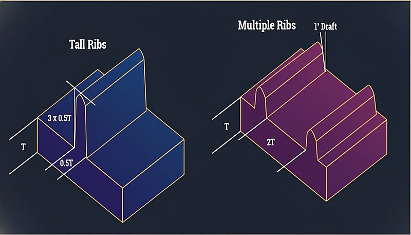
- 高いリブを少数配置する代わりに、複数の短いリブを使用して応力を分散させ、成形性を向上させます
プラスチック製品設計におけるリブとは何ですか?
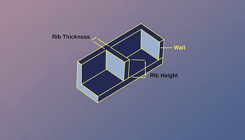
リブは、プラスチック部品に大幅な材料や重量を追加することなく構造剛性を高めるために設計された、薄く突出した壁状の特徴です。リブを設計の背骨と考えてください — それらは戦略的な補強材であり、 断面二次モーメント2 重要な領域でのたわみを防止します。 射出成形、リブは部品の片面に現れる隆起した形状で、主壁面から垂直または角度を持って伸びています。
工学的観点から、リブは材料を曲げの中立軸から遠ざけることで機能します。これにより断面二次モーメントが増加し、剛性に直接関連します。適切に配置されたリブは、単に全体の肉厚を増やす場合と比べて材料を10-15%しか追加せずに、局所剛性を300-500%向上させることができます。
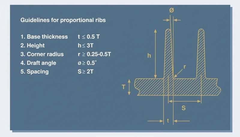
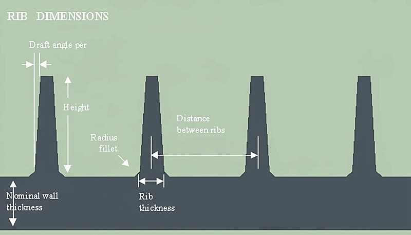
射出成形リブの主な特徴: ベース厚さ:公称肉厚の40〜60%。高さ:通常、リブ厚さの2〜3倍。 抜き勾配3:片側あたり最低0.5°、できれば1〜2°。フィレット半径:ベース接合部で0.2〜0.5mm。
リブは、構造要件に応じて直線状、曲線状、または複雑な格子パターンで配置できます。最も一般的な用途には、大きな平坦面の剛性向上、取付ボスの補強、リビングヒンジの作成、コスト重視設計における厚肉断面の置き換えなどがあります。これらの特徴を適切にサイズ設定し配置する方法を理解することは、プラスチック製品を扱うすべてのエンジニアにとって不可欠です。
なぜプラスチック製品にはリブが必要なのですか?
リブは、肉厚を増やすことなくプラスチック部品に剛性を加える構造補強要素です。エンジニアリングプラスチックの弾性率は金属よりも50〜200倍低く(1〜4 GPa対200 GPa)、荷重下でのたわみがはるかに大きくなります。リブは、最小限の追加材料で、最も重要な場所の断面二次モーメントを増加させ、サイクルタイムを短く保つことでこの問題を解決します。
リブ設計の4つの主な理由は:
材料効率: リブ付き設計は、均一な厚肉壁と同等の剛性を、20〜40%少ない材料で実現できます。大量生産では、これは相当なコスト削減につながります。例えば、4mmの厚肉壁を2mmの壁と最適化されたリブに置き換えると、曲げ強度を維持しながら材料使用量を35%削減できます。
サイクルタイムの短縮: 肉厚が厚いと冷却が遅く、生産のボトルネックとなります。冷却時間は肉厚の二乗に比例します — 肉厚を2倍にすると冷却時間は4倍になります。厚肉断面の代わりにリブを使用することで、サイクルタイムを15〜25%短縮でき、生産性を直接向上させることができます。
寸法安定性: 厚い部分は冷却中に不均一に収縮し、反り、シンクマーク、内部応力を引き起こします。リブを使用することで、構造性能を維持しながら壁断面を薄く均一に保ち、より優れた寸法制御と表面品質を実現できます。
設計の柔軟性: リブを使用すると、必要な場所に正確に剛性を調整できます。部品全体を過剰設計する代わりに、高応力領域に戦略的に補強を配置し、低応力領域は薄く軽量に保つことができます。
適切なリブ設計により部品重量を30%削減しながら剛性を200%向上させたプロジェクトを担当しました。重要なのは、リブが単なるコスト削減策ではなく、総合的な設計性能を高める高度なエンジニアリングツールであると理解することです。当社の工場では、生産用金型を承認する前に、金型流動解析と初回射出測定でリブ変更を検証しています。
リブ設計の主要なガイドラインは何ですか?
リブ設計の主要なガイドラインは、厚さ比率、高さ制限、抜き勾配、フィレット半径、間隔です。それぞれが構造強度と成形性のバランスを取る必要があり、一つでも誤るとシンクマーク、反り、または離型不良の原因となります。
厚さ比率(40〜60%ルール): リブの厚さは、公称肉厚の40〜60%であるべきです。この比率は、十分な強度を維持しながらシンクマークを防ぎます。2mmの壁の場合、リブの厚さは0.8〜1.2mmであるべきです。正確な割合は、材料と外観要件によって異なります:化粧部品はシンクマークを最小限にするため40〜50%を使用します。構造部品は最大強度のために50〜60%を使用します。半結晶性材料は収縮率が高いため40%に近い値を維持すべきです。非晶質材料はリスクが少ないため60%に向けて押し上げることができます。
高さのガイドライン:
リブの高さは、リブの厚さの3倍を超えてはならず、2〜2.5倍が最適です。厚さ1mmのリブは、高さ3mmを超えず、できれば2〜2.5mmであるべきです。この比率を超えると、リブは充填が困難になり、荷重下で座屈する可能性があります。剛性の利点は高さと立方関係にあり、高さを2倍にすると剛性は8倍になりますが、リブが適切に成形され、圧縮で破損しない場合に限ります。
抜き勾配の要件:
最低でも側面あたり0.5°が必要ですが、量産用金型では1-2°を強く推奨します。深いリブは側面あたり少なくとも1°必要です。金型キャビティにテクスチャーを施す場合は、側面あたりさらに1°追加してください。滑らかな表面の場合、抜き勾配 = 0.5° + 0.035° × (高さ mm) が良い出発点の公式です。
フィレット半径:
リブがベース壁面に接する部分には常に小さな半径(0.2-0.5mm)を設けてください。鋭角は応力集中を生み、金型加工も困難です。半径は射出成形時の材料流動にも役立ちます。
間隔の考慮事項:
平行なリブは、少なくとも肉厚の2倍間隔で配置し、3-4倍が理想的です。間隔が狭すぎるとリブ間に厚い部分が生まれ、リブの利点が損なわれます。肉厚2mmの場合、リブ間隔は少なくとも4mm、できれば6-8mm離してください。
適切なリブの厚さはどのように決定しますか?
適切なリブ厚は、材料、外観、構造要求に応じて、公称肉厚の40–60%です。標準的な40-60%ルールは出発点を提供しますが、材料特性、部品形状、品質要求が最終決定に影響します。
材料分類から始めます:
非晶質材料(ABS、PC、PVC)は0.3-0.7%収縮し、深刻なシンクマークなしで壁厚の60%までのリブ厚さに耐えます。半結晶性材料(PE、PP、POM、ナイロン)は1.5-3%収縮し、表面欠陥を防ぐために40-50%に近い厚さを維持すべきです。
最大許容厚さの計算:
外観面では、初回設計において最大リブ厚さ=壁厚×0.4の式を使用します。シンクマークの影響が少ない隠れた面やテクスチャ面では、壁厚×0.6まで厚くすることが可能です。
部品の機能を考慮:
構造部品は厚いリブ(55-60%範囲)を使用できます。なぜなら、外観は性能に次ぐものです。外観用ハウジングは表面品質を維持するために40-45%範囲に留まるべきです。部品が塗装またはテクスチャ加工される場合、軽微なシンクマークは許容され、厚さ範囲の上限を使用できます。
肉厚変動を考慮:
実際の射出成形部品では、プロセス制御に応じて±0.05~0.15mmの厚さ変動が生じます。ベース壁が厚くなると、リブ厚が実厚さに対する比率が高くなり、シンクマークリスクが増大します。この変動を考慮するため、公称壁厚から標準偏差1つ分を引いた値に基づいてリブを設計することを推奨します。
モールドフロー解析による検証:
重要な用途では、シンクマークの深刻度を予測するためにモールドフロー解析を実行します。ソフトウェアは冷却パターンをモデル化し、表面欠陥が発生する場所を予測できます。これは、手動計算が困難になる複雑なリブパターンにおいて特に価値があります。
私が使用する実用的なアプローチ:新設計では45%から開始し、プロトタイプ結果に基づいて調整します。シンクマークが現れた場合、0.05-0.1mm単位で厚さを減少させます。構造性能が不十分な場合、壁厚の60%を超えるよりも、厚さを増加させたり、リブを追加します。
リブの高さと構造強度の関係は何ですか?
リブ高さと構造強度は立方則で関連しています — 高さを2倍にすると約8倍の剛性が得られます。これはリブが成形中に安定し適切に充填される場合にのみ成立し、効率的な設計には高さの最適化が重要です。
立方関係の説明:
剛性は中立軸からの距離の立方に比例します。リブの高さを2倍にすると、材料を曲げ中心線から遠ざけることになり、劇的な剛性向上が得られます。ただし、この理論的な利点は、リブが完全な断面を維持し、座屈や圧縮破壊を起こさないことを前提としています。
実用的な高さの制限:
高いリブは剛性を向上させますが、製造上の制約により実用的な高さはリブ厚の3倍に制限されます。この比率を超えると、充填不足などいくつかの問題が発生します: 射出成形金型 加工、圧縮荷重下での座屈傾向の増加、適切な抜き勾配の達成困難、金型離型の課題。
複数リブの利点:
構造的・製造上の理由から、一般的に高リブを少数配置するよりも、低リブを複数配置する方が優れた性能を発揮します。材料使用量が同等でも、高さ2mmのリブ3本は高さ6mmのリブ1本よりも均一な応力分布を実現します。低リブは成形が容易で座屈のリスクが低く、シンクマークの問題も軽減されます。
用途別の最適な高さと厚さの比率: 化粧部品はシンクマークを最小化するため2:1の比率を使用します。一般的な構造部品はバランスの取れた性能のために2.5:1の比率を使用します。高強度用途では最大許容値として3:1の比率に達することができます。深絞り部品はエジェクションの問題から1.5-2:1の比率を使用します。
高さ分布の戦略:
複雑な荷重条件では、局所的な応力要件に基づいてリブの高さを調整します。高応力領域では高いリブを、一般的な補強には低いリブを使用します。このアプローチは、製造性を維持しながら材料分布を最適化します。リブの効果はシステム全体に依存することを常に念頭に置いてください。高さ、厚さ、間隔、方向性が連携して構造目標を達成する必要があります。
リブの位置は部品性能にどのように影響しますか?
リブ位置は荷重分散の主要因であり、適切な配置により剛性が300~500%向上します。不適切な配置は材料の無駄、サイクルタイムの増加を招き、最小限の構造的利点しか得られない可能性があります。
戦略的配置の原則:
最大の効果を得るために、主応力方向に対して垂直にリブを配置します。部品が曲げ荷重を受ける場合、曲げの中立軸に平行にリブを配置します。ねじり荷重の場合、対角線または交差パターンで走るリブを使用します。応力解析または試験を通じて荷重条件を理解することが重要です。
交互配置と均一配置:
交互配置のリブパターンは一般に均一間隔よりも優れています。なぜなら、応力をより均等に分散し、平行線でのクラック伝播リスクを減少させるからです。10mm毎にリブを配置する代わりに、8-12mmの間隔を変えて応力集中パターンを分散させます。このアプローチは圧縮荷重下での座屈抵抗も向上させます。
応力集中部の回避:
リブを壁面の途中で突然終端させないでください。これは応力集中点を生み、クラックの起点となります。代わりに、リブ高さの2~3倍の距離にわたって高さを徐々にゼロに漸減させてください。リブが他の形状と交差する箇所では、適切なフィレット半径で滑らかな遷移を維持します。
材料流動の考慮事項:
リブの配置は射出成形時の樹脂流動に影響します。流動方向に垂直なリブは溶接ラインやエアトラップを生じさせ、流動方向に平行なリブは材料の流れを誘導し充填性を向上させます。リブ配置時にはゲート位置を考慮し、成形サイクルの初期に充填される領域に重要な構造リブを配置してください。
組み立てと取り付けの統合:
集中荷重が発生する取り付け点、スナップフィット構造、組み立てインターフェースの補強にリブを使用します。一般的なミスは、十分なリブ補強なしに取り付けボスを設計し、ファスナー周辺に応力クラックを生じさせることです。取り付け部品をリブで囲み、荷重を主構造に分散させてください。
避けるべき一般的なリブ設計のミスは何ですか?
最も一般的なリブ設計の誤りには、厚さ比率の無視、不適切な抜き勾配、材料挙動の理解不足が含まれます。これらの誤りは一貫して生産問題、品質問題、高額な設計修正を引き起こします。
過大なリブ厚さ: 肉厚の60%を超えるリブは、化粧表面に目立つシンクマークを、構造部品には内部ボイドを引き起こします。材料がリブと壁の接合部に堆積し、不均一に冷却されます。
抜き勾配不足: 最小限またはゼロの抜き勾配はエジェクション問題を引き起こし、リブ表面を傷つけ金型を損傷します。ほとんどの量産リブには少なくとも片側1°が必要で、深いリブにはきれいな離型のために1.5°以上が必要です。
材料収縮の無視: ナイロンやPOMなどの半結晶性材料は1.5-3%収縮しますが、ABSやPCなどの非晶質樹脂は0.3-0.7%しか収縮しません。この違いを考慮せずにリブを設計すると、寸法不良や組み立て問題が発生します。
不適切なリブ終端:
リブを急に終端させると応力集中が生じ、き裂の起点となります。リブは常に徐々にテーパーさせるか、他の構造要素に接続してください。急激な遷移は製造上の弱点となり、現場での故障を引き起こします。
両側に対向するリブ: リブを直接対向させて配置すると、実効肉厚が2倍になり、深刻なシンクマークと冷却時間の延長を引き起こします。この問題を避けるために対向リブは常に少なくともリブ幅1つ分ずらして配置してください。
不適切な間隔: リブを近接配置すると厚肉部が生じ、シンクマークを引き起こし、サイクルタイムを延長します。平行なリブ間の間隔は少なくとも壁厚の2倍、理想的には3~4倍を維持してください。
上海の工場では、90Tから1850Tまでの47台の射出成形機を使用し、400以上の材料を加工しています。DFM分析では8人の上級エンジニアがすべてのリブ設計をレビューし、鋼材切削前に厚さの問題、抜き勾配の問題、シンクマークのリスクを捕捉します。20年以上の射出成形と金型経験により、10%のリブ厚さ削減がシンクマークを完全に排除し、生産ラインを救うことを直接経験しています。
材料特性はリブ設計にどのように影響しますか?
材料特性(収縮率、弾性率、結晶性)がリブ設計の主要な決定要因です。これらの基本原理を理解することで、高額な金型修正や生産不良を防ぐことができます。
Amorphous vs. semi-crystalline behavior:
Amorphous materials (ABS, PC, PMMA) shrink uniformly at 0.3-0.7% and can accommodate rib thicknesses up to 60% of wall thickness. Their predictable shrinkage makes rib design more forgiving. Semi-crystalline materials (PE, PP, POM, Nylon) shrink 1.5-3% with less predictable patterns, requiring conservative rib thickness of 40-50% maximum.
Modulus considerations:
High-modulus materials like glass-filled nylons (8-15 GPa) may not need aggressive ribbing since the base material provides substantial stiffness. Low-modulus materials like polyethylene (0.2-0.4 GPa) require extensive ribbing for structural applications. The return on investment from ribbing decreases as base material modulus increases.
Shrinkage-specific rib ratios: ABS and PC can use up to 60% wall thickness. PP and PE should stay at 45-50% maximum. POM and Nylon work best at 40-45% recommended. Glass-filled materials require a 5-10% reduction due to anisotropic shrinkage.
“Using more shorter ribs is generally better than fewer tall ribs.”真
Multiple shorter ribs distribute stress more evenly and reduce the risk of sink marks and warpage compared to tall, thick ribs.
“Rib thickness should equal the nominal wall thickness for maximum strength.”偽
Ribs should be 40-60% of wall thickness. Full-thickness ribs cause sink marks, warpage, and internal voids — they actually weaken the part.
Flow characteristics impact:
High-flow materials can fill thin ribs more easily, allowing you to use the lower end of thickness ratios while maintaining adequate strength. Low-flow or high-viscosity materials may require slightly thicker ribs to ensure complete filling, but this must be balanced against sink mark risk.
Working with your supplier:
Material selection significantly impacts rib design feasibility and cost. When working with an 射出成形サプライヤー, discuss material-specific rib guidelines during the design phase. Experienced suppliers can provide material-specific recommendations based on their processing experience and help optimize rib designs for both performance and manufacturability.
Temperature considerations:
High-temperature materials may require different rib designs due to thermal expansion and creep behavior. Materials used above their glass transition temperature need more conservative rib spacing and thickness to maintain long-term dimensional stability.
Understanding these fundamental truths about rib behavior helps you avoid the most common design errors. The difference between theoretical guidelines and production reality is where most projects encounter problems. In practice, material selection, gate placement, and cooling channel design all interact with rib geometry in ways that simple rules of thumb cannot fully capture. This is why experienced tooling engineers always validate rib designs through mold flow simulation before committing to steel. The cost of catching issues during simulation is roughly one percent of the cost of reworking a finished mold.
“Ribs can replace thick wall sections to reduce material usage while maintaining stiffness.”真
This is the primary purpose of ribbing. A well-designed rib pattern can achieve equivalent stiffness with 20-40% less material compared to a uniform thick wall.
“A draft angle of 0.5° is sufficient for all rib designs.”偽
While 0.5° is the absolute minimum, most applications benefit from 1°-2° draft. Deep ribs or textured surfaces may need even more draft to ensure clean ejection.
FAQ:リブ設計に関する最も一般的な質問は何ですか?
What is the recommended rib thickness ratio for injection molding?
The standard recommendation is 40-60% of the nominal wall thickness. For cosmetic parts where sink marks are critical, stay at 40% or below. For structural parts where appearance is less important, you can push toward 60%. The exact ratio also depends on the material — amorphous materials like ABS tolerate slightly thicker ribs than semi-crystalline materials like nylon. Always consult with your tooling manufacturer during the DFM phase to validate rib dimensions against the specific material grade and production conditions you plan to use. The interaction between rib geometry, gate location, and cooling time is complex enough that generic guidelines should be treated as starting points, not final specifications.
How tall should a rib be compared to its thickness?
A rib should typically be no taller than 3 times its base thickness. Beyond this ratio, the rib becomes difficult to fill during molding and may buckle under load. In practice, most successful designs use a height-to-thickness ratio of 2:1 to 2.5:1, balancing structural gain against manufacturability. Always consult with your tooling manufacturer during the DFM phase to validate rib dimensions against the specific material grade and production conditions you plan to use. The interaction between rib geometry, gate location, and cooling time is complex enough that generic guidelines should be treated as starting points, not final specifications.
What draft angle is needed for ribs in injection molding?
Ribs need a minimum draft angle of 0.5° per side, but 1° to 2° is strongly recommended for production tooling. Deep ribs (height over 20mm) should use at least 1.5° draft. If the mold surface is textured, add at least 1° extra draft per side to prevent scraping during ejection. Always consult with your tooling manufacturer during the DFM phase to validate rib dimensions against the specific material grade and production conditions you plan to use. The interaction between rib geometry, gate location, and cooling time is complex enough that generic guidelines should be treated as starting points, not final specifications.
How do you prevent sink marks near ribs?
Sink marks appear when rib thickness causes localized thick sections that cool unevenly. To minimize them: keep rib thickness at or below 50% of wall thickness, add a small radius (0.2-0.5mm) at the rib-wall junction, and consider using a foaming agent or gas-assist molding for thick-walled parts. Moving the gate closer to the rib area can also help by maintaining pack pressure. Always consult with your tooling manufacturer during the DFM phase to validate rib dimensions against the specific material grade and production conditions you plan to use. The interaction between rib geometry, gate location, and cooling time is complex enough that generic guidelines should be treated as starting points, not final specifications.
What spacing should be used between parallel ribs?
Parallel ribs should be spaced at least 2 times the nominal wall thickness apart, with 3-4 times being ideal for most applications. Spacing that is too narrow creates thick sections between ribs, leading to sink marks, warpage, and extended cycle times. Staggered rib patterns generally perform better than uniformly spaced parallel ribs. Always consult with your tooling manufacturer during the DFM phase to validate rib dimensions against the specific material grade and production conditions you plan to use. The interaction between rib geometry, gate location, and cooling time is complex enough that generic guidelines should be treated as starting points, not final specifications.
Can ribs be used on both sides of a wall simultaneously?
Yes, but with caution. When ribs appear on both sides of a wall, they must be offset — never directly opposite each other. Directly opposing ribs create an effective wall thickness equal to the wall plus both ribs, causing severe sink marks and very long cooling times. Offset the ribs by at least one rib width to avoid this issue. Always consult with your tooling manufacturer during the DFM phase to validate rib dimensions against the specific material grade and production conditions you plan to use. The interaction between rib geometry, gate location, and cooling time is complex enough that generic guidelines should be treated as starting points, not final specifications.
Need Expert DFM Review for Your Rib Design?
ZetarMold’s engineering team provides free Design for Manufacturing (DFM) analysis on every project. With 20+ years of experience across 400+ materials, we catch rib design issues before tooling begins — saving you time and money. Request a Free Quote and get expert feedback within 24 hours.
-
シンク跡: sink marks refers to surface depressions on injection molded parts caused by uneven cooling and material shrinkage at thick sections like rib-wall junctions. ↩
-
断面二次モーメント: moment of inertia refers to a measure of a cross-section’s resistance to bending. Adding ribs increases the moment of inertia without significantly increasing material usage. ↩
-
抜き勾配: draft angle refers to the taper applied to vertical surfaces of a mold cavity to allow the part to be ejected without damage. Ribs typically need 0.5°-2° draft per side. ↩


