Die Einspritzgeschwindigkeit – also die Geschwindigkeit, mit der die Schnecke den geschmolzenen Kunststoff in die Formkavität drückt – gehört zu den wirksamsten Parametern einer Spritzgießmaschine. Ist sie richtig eingestellt, entstehen Zyklus für Zyklus glänzende, maßhaltige Teile. Ist sie falsch eingestellt, kämpfen Sie fortwährend mit Gratbildung, unvollständiger Füllung, Einfallstellen und Verzug. In unserem Werk in Shanghai optimieren wir seit mehr als 20 Jahren Geschwindigkeitsprofile an Maschinen von 90 T bis 1850 T. Dieser Leitfaden fasst zusammen, worauf es wirklich ankommt.
- Die Einspritzgeschwindigkeit steuert unmittelbar Schmelzedurchsatz, Kavitätsdruck und Bauteilqualität
- Mehrstufige Geschwindigkeitsprofile übertreffen bei den meisten Teilen eine Füllung mit konstanter Geschwindigkeit
- Dünnwandige Teile erfordern höhere Geschwindigkeiten; dickwandige Teile benötigen langsam-schnell-langsam verlaufende Profile
- Durch Anpassen der Geschwindigkeit lassen sich Gratbildung, unvollständige Füllung, Freistrahlbildung und Brandstellen beheben
- Materialviskosität und Anschnittgestaltung bestimmen den anfänglichen Geschwindigkeitsbereich
Was ist die Einspritzgeschwindigkeit beim Spritzgießen?
Die Einspritzgeschwindigkeit ist die Schneckengeschwindigkeit, mit der die Formkavität mit Kunststoffschmelze gefüllt wird. Sie wird üblicherweise in mm/s oder cm3/s angegeben und ist der erste Einstellhebel, sobald Schmelzetemperatur, Formtemperatur und Schließkraft stabil sind. Wenn Sie Anbieter vergleichen oder die Beschaffung planen, behandelt unser Leitfaden zur Auswahl von Spritzgießlieferanten die Vorbereitung von Angebotsanfragen und die Lieferantenprüfung.
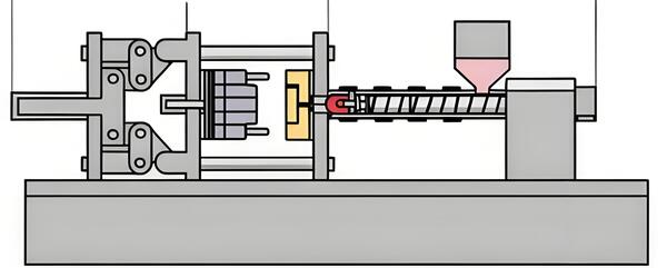
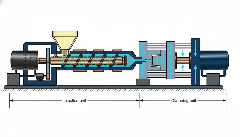
Die Einspritzgeschwindigkeit ist die Rate, mit der die Schnecke geschmolzenes Polymer in den Formhohlraum fördert, gemessen in mm/s oder cm/s. Sie bestimmt, wie schnell sich der Hohlraum füllt, bevor das Material zu erstarren beginnt. Bei einer hydraulischen Maschine wird die Einspritzgeschwindigkeit durch den Durchfluss von Hydrauliköl zum Einspritzzyllinder gesteuert. Bei einer vollelektrischen Maschine treibt ein Servomotor die Schnecke an, und die Geschwindigkeit wird direkt als digitaler Parameter eingestellt.
Der Zusammenhang zwischen Geschwindigkeit und Teilequalität ist nicht linear. Unterhalb eines bestimmten Schwellenwerts kühlt die Schmelze während des Füllens zu stark ab, wodurch schwache Bindenähte, Fließmarken und ungleichmäßige Dichte entstehen. Oberhalb eines anderen Schwellenwerts strömt die Schmelze turbulent in die Kavität, schließt Luft ein, verursacht Freistrahlbildung und erzeugt übermäßige Scherwärme, die das Polymer schädigen kann. Der optimale Bereich – für jede Form und jedes Material unterschiedlich – liegt dort, wo die Fließfront stetig voranschreitet, gleichmäßig füllt und vollständig nachverdichtet wird.
In der Praxis beeinflusst die Einspritzgeschwindigkeit gemeinsam mit Einspritzdruck, Schmelzetemperatur und Formtemperatur den Prozess. Die Geschwindigkeit kann nicht isoliert optimiert werden. Sie ist jedoch meist der erste Parameter, der nach dem Einstellen von Zylindertemperaturen und Schließkraft abgestimmt wird, weil ihre Auswirkungen auf Oberflächenbild und Maßhaltigkeit unmittelbar und offensichtlich sind.
In unserem Werk in Shanghai betreiben wir 47 Spritzgießmaschinen von 90T bis 1850T. Über Tausende von Produktionsläufen hinweg haben wir festgestellt, dass die Einspritzgeschwindigkeit der wichtigste Parameter ist, der bei der anfänglichen Prozesseinrichtung korrekt eingestellt werden muss — bei den meisten Teilen wichtiger als Nachdruck oder Kühlzeit.
Warum ist die Einspritzgeschwindigkeit für die Teilequalität wichtig?
Die Einspritzgeschwindigkeit ist eine primäre Steuergröße für die Qualität des Formteils. Sie bestimmt die Schmelzfrontgeschwindigkeit, den Kavitätendruck und die Gleichmäßigkeit der Abkühlung. Wenn die Schmelze zu langsam einströmt, kühlt das Polymer ab, bevor der Hohlraum voll ist, was zu Kaltläufern, schwachen Nahtstellen, ungleichmäßiger Dichte und unvollständigem Nachdruck führt. Wenn sie zu schnell einströmt, kann der Prozess Strahlenbildung, Lufteinschlüsse, Grat, Brandflecken und übermäßige Scherwärme verursachen.
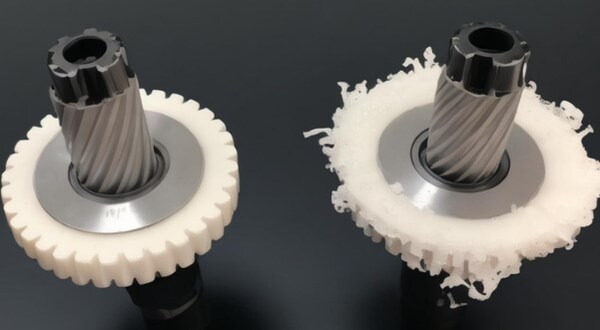
Tritt die Schmelze zu schnell ein, entstehen andere Probleme: Freistrahlbildung, bei der die Schmelze wie aus einem Feuerwehrschlauch durch den Anschnitt schießt, statt sich als gleichmäßige Front auszubreiten; Lufteinschlüsse durch turbulente Strömung, die Brandstellen und Hohlräume verursachen; Gratbildung an der Trennlinie durch den plötzlichen Druckanstieg sowie Oberflächenfehler wie Silberschlieren durch Feuchtigkeit oder Gas.
Die ideale Geschwindigkeit hält die Fließfrontgeschwindigkeit während des gesamten Füllvorgangs konstant. Da sich die Querschnittsfläche der Kavität entlang des Fließwegs ändert, muss sich auch die Schneckengeschwindigkeit ändern – genau deshalb gibt es die mehrstufige Geschwindigkeitsprofilierung1. Jede Füllphase erfordert eine andere Geschwindigkeit, damit sich die Fließfront gleichmäßig vorwärtsbewegt.
"Dünnwandige Bauteile erfordern im Allgemeinen höhere Einspritzgeschwindigkeiten als dickwandige Bauteile."True
Dünne Wände erstarren innerhalb von Millisekunden. Die Schmelze muss die gesamte Kavität füllen, bevor der Fließkanal erstarrt. Dafür sind höhere Einspritzgeschwindigkeiten erforderlich — bei Wanddicken unter 0,5 mm häufig 200 mm/s oder mehr.
"Einspritzgeschwindigkeit und Einspritzdruck sind vollständig unabhängige Parameter."False
Obwohl die Maschineneinstellungen getrennt zu betrachten sind, erhöht eine höhere Einspritzgeschwindigkeit aufgrund des größeren Volumenstroms und der stärkeren Schererwärmung in der Regel den Kavitätsdruck.
Welche Faktoren beeinflussen die Einspritzgeschwindigkeit?
Die Hauptfaktoren, die die Einspritzgeschwindigkeit beeinflussen, sind Materialviskosität, Wandstärke, Angussdesign, Fließweg und Maschinenkapazität. Niedrigviskose Materialien wie PP und PA können mit moderater Geschwindigkeit gefüllt werden, während PC, PMMA und glasfasergefüllte Materialien eine strengere Kontrolle benötigen, um Scherschäden zu vermeiden. Dünne Wände benötigen eine schnellere Füllung vor dem Einfrieren, während dickere Wände normalerweise ein langsames-schnelles-langsames Profil benötigen.
Die Wanddicke spielt eine entscheidende Rolle. Dünnwandige Teile unter 1 mm erfordern eine hohe Geschwindigkeit, damit sie vor dem Erstarren gefüllt werden. Dickwandige Teile über 3 mm profitieren von einem Langsam-schnell-langsam-Profil, das Einfallstellen und Hohlräume minimiert und zugleich angemessene Zykluszeiten ermöglicht. Auch Art und Größe des Anschnitts sind relevant – ein Punktanschnitt erzeugt am Eintritt hohe Scherung, weshalb die Geschwindigkeit durch den Anschnitt kontrolliert werden muss, während ein großer Kantenanschnitt höhere Geschwindigkeiten verträgt.
Die Fließweglänge ist ein weiterer entscheidender Faktor. Lange Fließwege erfordern eine höhere Geschwindigkeit, um die Schmelzetemperatur aufrechtzuerhalten. Kühlt das Polymer während der Füllung ab, entstehen unvollständig gefüllte Teile. Als Faustregel gilt: Pro 100 mm Fließweglänge sollte die Geschwindigkeit zum Ausgleich des Wärmeverlusts um 10 bis 20 mm/s erhöht werden. Auch die Werkzeugtemperatur spielt eine Rolle — ein wärmeres Werkzeug ermöglicht geringere Geschwindigkeiten, da die Schmelze länger fließfähig bleibt.
Letztlich setzt die Leistungsfähigkeit der Maschine die Obergrenze. Die maximale Einspritzgeschwindigkeit hängt vom Hydraulikvolumenstrom beziehungsweise von der Drehzahl des Servomotors ab. Eine Maschine mit einer maximalen Nennleistung von 300 mm/s kann möglicherweise nur zwischen 20 und 250 mm/s eine stabile Geschwindigkeitsregelung gewährleisten. Das Zusammenspiel dieser Faktoren zu verstehen, ist entscheidend, um die passende Definition der Einspritzgeschwindigkeit2 für Ihre konkrete Anwendung zu wählen.
Wie steuern Sie die Einspritzgeschwindigkeit?
Sie steuern die Einspritzgeschwindigkeit durch Programmieren des Hydraulikventilflusses, der geschlossenen Servogeschwindigkeit oder der servoelektrischen Spindelbewegung. Proportionalventilsteuerung reguliert den Ölfluss zum Einspritzylinder, während Servosysteme die tatsächliche Spindelposition und -geschwindigkeit in Echtzeit messen. Für Präzisionsteile bietet die geschlossene Regelung eine viel bessere Wiederholgenauigkeit als offene Geschwindigkeitseinstellungen.
Die geschlossene Servoregelung verwendet einen hochauflösenden Encoder an der Schnecke, um die tatsächliche Position und Geschwindigkeit in Echtzeit zu messen. Die Steuerung passt den Servomotor oder das Proportionalventil an den Sollwert an. Dies ermöglicht eine Geschwindigkeitsgenauigkeit von plus/minus 0,1 Prozent und ist für den Präzisionsspritzguss unerlässlich — insbesondere bei medizinischen, optischen und elektronischen Teilen, bei denen die Konstanz von Schuss zu Schuss die Bauteilqualität direkt beeinflusst.
Der servoelektrische Direktantrieb kommt vollständig ohne Hydraulik aus. Eine von einem Servomotor angetriebene Kugelumlaufspindel bewegt die Spritzeinheit. Die Geschwindigkeitsregelung ist von Grund auf digital und erreicht Reaktionszeiten unter 10 ms. Diese Maschinen bieten die konstanteste Geschwindigkeit von Schuss zu Schuss und die saubersten Geschwindigkeitsübergänge zwischen den Stufen.
Auf Prozessebene können Sie bei den meisten modernen Steuerungen 5 bis 10 Geschwindigkeitsstufen programmieren. Jede Stufe legt eine Schneckenposition und eine Zielgeschwindigkeit fest. Während sich die Schnecke vorwärtsbewegt, wechselt die Maschine automatisch zwischen den Stufen. So können Sie am Anguss verlangsamen, durch die Kavität beschleunigen und am Füllende erneut verlangsamen — alles in einem einzigen Schuss.
Bei allen unseren 47 Maschinen von 90T bis 1850T verwenden wir eine geschlossene Geschwindigkeitsregelung. Der Unterschied zwischen offener und geschlossener Geschwindigkeitsregelung zeigt sich am deutlichsten bei Teilen mit engen Toleranzen – allein durch den Wechsel zu einem geschlossenen Einspritzgeschwindigkeitsprofil konnten wir die Maßabweichung um 40 bis 60 Prozent senken.
Was ist ein mehrstufiges Einspritzgeschwindigkeitsprofil?
Bei der mehrstufigen Profilierung wird die Einspritzgeschwindigkeit an festgelegten Punkten der Füllphase geändert. Statt die Schnecke mit einer konstanten Geschwindigkeit zu betreiben, programmieren Sie eine Geschwindigkeitskurve, die sich an die Vorgänge im Werkzeug anpasst. Ein typisches fünfstufiges Profil unterteilt den Füllprozess in klar getrennte Phasen mit jeweils eigenem Geschwindigkeitsziel.
Stufe 1 ist das Füllen des Angusskanals mit hoher Geschwindigkeit, typischerweise 80 bis 100 Prozent des Maximums. Der Angusskanal unterliegt keinen optischen oder strukturellen Anforderungen, daher hat die Geschwindigkeit Vorrang, um den Wärmeverlust zu minimieren. Stufe 2 ist der Eintritt durch den Anschnitt mit niedriger Geschwindigkeit, die beim Durchtritt der Schmelze durch den Anschnitt auf 20 bis 40 Prozent sinkt. Dies verhindert Freistrahlbildung, reduziert Scherspannungen und vermeidet Anschnittschlieren. Bei Punktanschnitten an Sichtteilen ist diese Stufe entscheidend.
Stufe 3 ist das schnelle Füllen der Kavität. Sobald die Schmelze den Anschnitt passiert hat und sich in der Kavität ausbreitet, wird die Geschwindigkeit wieder auf 60 bis 90 Prozent erhöht. In dieser Stufe werden typischerweise 70 bis 85 Prozent des Bauteilvolumens gefüllt. Stufe 4 ist die Übergangsphase bei mittlerer Geschwindigkeit. Wenn die Kavität nahezu gefüllt ist, wird auf 30 bis 50 Prozent reduziert, um einen gleichmäßigen Übergang zur Nachdruckphase zu schaffen und ein Überpacken in Anschnittnähe zu vermeiden.
Stufe 5 beendet die Füllung bei niedriger Geschwindigkeit; für die letzte Füllphase wird sie auf 10 bis 20 Prozent reduziert. Dadurch werden Gratbildung verhindert, eingeschlossene Luft kann über die Entlüftungen entweichen und der Übergang zum Nachdruck erfolgt sauber. Die genauen Geschwindigkeitsanteile und positionsabhängigen Umschaltpunkte richten sich nach Form und Material. Das optimale Profil zu ermitteln, gehört zur wissenschaftlichen Spritzgießmethodik3: Dabei werden Teilfüllungen mit unterschiedlichen Geschwindigkeiten gefahren, das Füllbild wird gemessen und die Einstellung schrittweise verbessert.
"Eine geringere Einspritzgeschwindigkeit in Anschnittnähe kann Freistrahlbildung und Anschnittschleier reduzieren."True
Eine Verringerung der Geschwindigkeit am Anguss minimiert die Scherbeanspruchung und verhindert, dass die Schmelze turbulent durch die Öffnung schießt. Dies ist eine der wirksamsten geschwindigkeitsbasierten Maßnahmen zur Fehlerbehebung.
"Eine einzige konstante Einspritzgeschwindigkeit während der gesamten Füllphase liefert die besten Ergebnisse."False
Ein mehrstufiges Geschwindigkeitsprofil ist einer Füllung mit konstanter Geschwindigkeit durchweg überlegen. Eine konstante Geschwindigkeit verursacht je nach gewähltem Wert Freistrahlbildung am Anschnitt, Gratbildung am Füllende oder beides.
Welche Probleme lassen sich durch eine Geschwindigkeitsanpassung lösen?
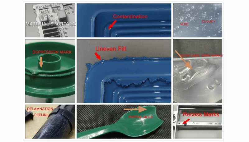
Die Einspritzgeschwindigkeit ist bei der Fehlerbehebung häufig der erste anzupassende Parameter. Gratbildung zählt zu den häufigsten Problemen: Tritt die Schmelze über die Trennfuge aus, wurde die Kavität am Ende der Füllung meist überpackt. Die Lösung besteht darin, die Geschwindigkeit in der letzten Stufe zu reduzieren, damit die Maschine ohne Druckspitze gleichmäßig auf den Nachdruck umschalten kann.
Kurzschüsse entstehen, wenn das Teil nicht vollständig gefüllt wird, weil die Schmelze vor Erreichen des Kavitätsendes erstarrt. Die Lösung besteht darin, die Geschwindigkeit während der Kavitätsfüllphase zu erhöhen, sodass die Schmelze heißer bleibt und weiter fließt. Freistrahlbildung erzeugt wurmähnliche Linien auf der Bauteiloberfläche nahe dem Anschnitt, wenn die Schmelze als schmaler Strahl durch den Anschnitt schießt, statt sich fächerförmig auszubreiten. Eine geringere Geschwindigkeit am Anschnitteintritt gibt der Schmelze Zeit, eine ordnungsgemäße Fließfront aufzubauen.
Brandstellen zeigen sich als dunkle Streifen oder verkohlte Bereiche, meist nahe dem Fließwegende oder in Sacktaschen, und werden durch komprimierte, überhitzte Luft verursacht. Die Lösung besteht darin, die Geschwindigkeit am Füllende zu verringern, damit die Luft durch die Entlüftungen entweichen kann, bevor die Kavität abgedichtet ist. Einfallstellen sind örtliche Vertiefungen auf der Teileoberfläche über dicken Bereichen oder Rippen. Obwohl Einfallstellen in erster Linie ein Nachdruckproblem sind, hilft eine höhere Einspritzgeschwindigkeit, indem sie dicken Bereichen heißeres Material zuführt.
Fließlinien sind sichtbare Wellen oder Unregelmäßigkeiten auf der Teileoberfläche, die durch eine uneinheitliche Geschwindigkeit der Schmelzefront verursacht werden. Zur Behebung wird das Geschwindigkeitsprofil so angepasst, dass die Schmelzefront eine konstante Geschwindigkeit beibehält, üblicherweise durch eine Erhöhung der Geschwindigkeit bei breiter werdendem Fließweg. Das Verständnis der Materialviskositätskurven hilft vorherzusagen, welche Geschwindigkeiten bei jedem Polymertyp den saubersten Fluss erzeugen.
Wie lässt sich die Einspritzgeschwindigkeit für verschiedene Materialien optimieren?
Die materialspezifische Geschwindigkeitsoptimierung ist der Prozess, jede Geschwindigkeitsstufe an die Polymerviskosität, Wandstärke und Wärmeempfindlichkeit anzupassen. Jedes Polymer hat eine Viskositätskurve, die bestimmt, wie es auf Geschwindigkeit und Scherung reagiert. Die folgende Tabelle gibt Startbereiche für gängige Materialien an; verfeinern Sie diese dann mit Kurzschussstudien und Kavitätendruckdaten während der Prozesseinrichtung.
| Werkstoff | Typischer Geschwindigkeitsbereich | Wichtiger Aspekt |
|---|---|---|
| PP (Polypropylen) | 50-150 mm/s | Niedrige Viskosität; schnelle Füllung, mäßige Scherung |
| PE (Polyethylen) | 50-120 mm/s | Ähnlich wie PP; bei dünnen Wänden auf Verzug achten |
| PA6/PA66 (Polyamid) | 60-180 mm/s | Schnelles Füllen erforderlich, um vorzeitiges Erstarren zu verhindern |
| ABS | 40-120 mm/s | Mittlere Viskosität; Geschwindigkeit beeinflusst die Gleichmäßigkeit des Glanzes |
| PC (Polycarbonat) | 30-100 mm/s | Hohe Viskosität; scherempfindlich; Spitzen am Anschnitt vermeiden |
| PMMA (Acryl) | 30-80 mm/s | Sehr hohe Viskosität; optische Klarheit erfordert gleichmäßiges Fließen |
| POM (Polyacetal) | 50-150 mm/s | Schnelle Kristallisation; erfordert zügiges Füllen |
| PBT | 60-140 mm/s | Kristallin; Geschwindigkeit beeinflusst Kristallinität und Schwindung |
| Glasfasergefüllt (PA+GF) | 80-200 mm/s | Hohe Geschwindigkeit erforderlich; Faserorientierung beachten |
| TPU | 30-80 mm/s | Geringe Schertoleranz; langsame Geschwindigkeiten verhindern Abbau |
Bei glasfaserverstärkten Materialien tragen höhere Einspritzgeschwindigkeiten dazu bei, die Faserlänge zu erhalten und die mechanischen Eigenschaften zu verbessern. Eine übermäßige Geschwindigkeit führt jedoch zu Faserbruch am Anschnitt und mindert damit die Verstärkungswirkung. Der optimale Bereich liegt bei Nylon mit 30 Prozent Glasfaseranteil typischerweise zwischen 100 und 150 mm/s. Bei wärmeempfindlichen Materialien wie PC und POM ist der mehrstufige Ansatz besonders wichtig – eine plötzliche Geschwindigkeitsspitze am Anschnitt kann genügend Scherwärme erzeugen, um das Polymer zu zersetzen.
Was sind bewährte Verfahren für die Einstellung der Einspritzgeschwindigkeit?
Auf Grundlage von zwei Jahrzehnten Produktionserfahrung befolgen wir diese Regeln. Erstens: Beginnen Sie mit einem entkoppelten Spritzgießansatz – füllen Sie die Kavität mithilfe der Geschwindigkeitsregelung zu 95 bis 99 Volumenprozent und wechseln Sie dann über den Nachdruck zur Druckregelung. Versuchen Sie nicht, gleichzeitig zu füllen und zu verdichten. Zweitens: Verwenden Sie stets ein mehrstufiges Geschwindigkeitsprofil. Nutzen Sie selbst bei einfachen Teilen mindestens ein 3-Stufen-Profil. Die bessere Konstanz rechtfertigt den Einrichtungsaufwand.
Drittens ermitteln Sie Ihr Profil durch eine Teilfüllungsanalyse. Stellen Sie die Maschine so ein, dass sie die Kavität zunächst nur teilweise füllt, und erhöhen Sie den Füllgrad schrittweise, während Sie das Fließbild beobachten. Viertens überwachen Sie den Kavitätsdruck und nicht nur die Schneckengeschwindigkeit. In der Spritzgießform zählen Schmelzedruck und Fließgeschwindigkeit – Kavitätsdrucksensoren zeigen Ihnen die tatsächlichen Verhältnisse.
Fünftens: Dokumentieren Sie Ihre Geschwindigkeitsprofile. Für jedes Werkzeug sollte eine Geschwindigkeitskurve als Teil der Prozessparameter dokumentiert sein. Wird ein Werkzeug auf eine andere Maschine verlagert, müssen die Geschwindigkeiten an deren neues Ansprechverhalten angepasst werden. Sechstens: Nach Änderungen der Materialcharge erneut validieren — unterschiedliche Chargen desselben Typs können eine geringfügig unterschiedliche Viskosität aufweisen; eine Geschwindigkeitsanpassung um 5 bis 10 Prozent reicht häufig zum Ausgleich.
Was sind die häufigsten Fragen zur Einspritzgeschwindigkeit?
Häufig gestellte Fragen
Was ist eine gute Einspritzgeschwindigkeit für das Spritzgießen?
Eine gute Einspritzgeschwindigkeit hängt von Ihrem Material und Ihrer Bauteilgeometrie ab. Für die meisten Thermoplaste liegen die Einspritzgeschwindigkeiten je nach Viskosität und Wandstärke zwischen 50 und 200 mm/s. Dünnwandige Teile unter 1 mm benötigen typischerweise Geschwindigkeiten über 150 mm/s, um sich vor dem Einfrieren vollständig zu füllen, während dickwandige Teile über 3 mm am besten bei 30 bis 80 mm/s funktionieren. Beginnen Sie mit 50 bis 70 Prozent der maximalen Maschinengeschwindigkeit und passen Sie sie basierend auf den Ergebnissen der Kurzschussanalyse während der anfänglichen Prozesseinrichtung an.
Wie beeinflusst die Einspritzgeschwindigkeit die Bauteilqualität?
Die Einspritzgeschwindigkeit steuert direkt die Schmelzfließrate, die Kavitätendruckübertragung und wie das Teil in jedem einzelnen Spritzgießzyklus erstarrt. Zu langsam verursacht Kurzschüsse, schwache Schweißnähte und unvollständige Füllung, weil die Schmelze abkühlt, bevor sie das Kavitätenende erreicht. Zu schnell verursacht Grat, Strahlenbildung, Brandflecken und eingeschlossene Luft durch übermäßige Schererwärmung und komprimiertes Gas. Die optimale Geschwindigkeit hält die Schmelzfrontgeschwindigkeit während des gesamten Füllens konstant und erzeugt gleichmäßige Wandstärke und konsistente strukturelle Integrität im gesamten Teil.
Was ist eine mehrstufige Einspritzgeschwindigkeitsprofilierung?
Mehrstufiges Profiling ändert die Einspritzgeschwindigkeit an bestimmten Schraubenpositionen während des Füllens, anstatt während des gesamten Schusses eine konstante Geschwindigkeit zu verwenden. Ein typisches Fünf-Stufen-Profil beginnt mit schnellem Angussfüllen bei 80 bis 100 Prozent der Maximalgeschwindigkeit, verlangsamt sich am Anguss, um Strahlenbildung zu verhindern, beschleunigt für die Kavitätenfüllung auf 60 bis 90 Prozent und endet mit einer langsamen Endfüllstufe, um Grat zu verhindern. Dieser Ansatz reduziert konsequent Fehler wie Grat, Brandflecken und Schweißnähte, indem das Einströmverhalten der Schmelze gesteuert wird.
Wie misst man die Einspritzgeschwindigkeit?
Die Einspritzgeschwindigkeit wird präzise als Verdrängungsgeschwindigkeit der Schnecke während der Füllphase gemessen, typischerweise ausgedrückt in Millimetern pro Sekunde oder Kubikzentimetern pro Sekunde. Moderne Maschinen mit geschlossenem Servoregelsystem verwenden hochauflösende Encoder, um die tatsächliche Schneckenposition und -geschwindigkeit in Echtzeit zu verfolgen und erreichen eine Genauigkeit innerhalb von 1 Prozent des Sollwerts. Die meisten Maschinensteuerungen zeigen sowohl die momentane Geschwindigkeit als auch die durchschnittliche Füllgeschwindigkeit an, sodass Bediener überprüfen können, dass jede Stufe eines mehrstufigen Profils während der Produktionsläufe korrekt ausgeführt wird.
Was ist der Unterschied zwischen Einspritzgeschwindigkeit und Einspritzdruck?
Die Einspritzgeschwindigkeit ist, wie schnell sich die Schnecke während der Füllphase vorwärts bewegt, während der Einspritzdruck die Kraft ist, die die Schmelze in den Hohlraum drückt. Die Geschwindigkeit steuert die Füllphase, und der Druck übernimmt während der folgenden Nachdruck- und Haltephasen. Beim entkoppelten Spritzgießen trennt man diese beiden Phasen bewusst für eine bessere Prozesskontrolle und Schuss-zu-Schuss-Wiederholgenauigkeit. Eine zu hohe Geschwindigkeitseinstellung erhöht den Druckbedarf und kann Grat verursachen, während eine zu niedrige Einstellung bedeutet, dass der Hohlraum möglicherweise nicht gefüllt wird, bevor das Material erstarrt.
Kann Einspritzgeschwindigkeit Gratfehler beheben?
Ja, Gratbildung ist einer der häufigsten Fehler, die durch Anpassung der Einspritzgeschwindigkeit in Produktionsumgebungen behoben werden. Gratbildung tritt auf, wenn die Schmelze aufgrund von übermäßigem Druck oder Geschwindigkeit am Ende der Füllphase über die Formtrennlinie fließt. Eine Reduzierung der Einspritzgeschwindigkeit während der finalen Füllphase ermöglicht es der Form, sich richtig zu schließen, bevor der Druck zu hoch wird. Eine mehrstufige Profilierung mit einer langsamen Endstufe bei 10 bis 20 Prozent der maximalen Geschwindigkeit ist die Standardkorrekturmaßnahme zur Gratvermeidung in Präzisionsspritzgießprozessen.
Welche Einspritzgeschwindigkeit sollte ich für ABS verwenden?
Für ABS beginnen Sie mit einer Füllgeschwindigkeit von 80 bis 150 mm/s und passen diese basierend auf der Bauteilgeometrie und den Wandstärkenanforderungen an. ABS hat eine moderate Viskosität und reagiert gut auf mehrstufige Profilierung mit einer schnellen Anfangsfüllung gefolgt von einer langsameren Endfüllstufe. Achten Sie auf Glanzmarkierungen auf der Bauteiloberfläche, die auf zu abrupte Geschwindigkeitsübergänge hinweisen. Wenn Sie Einfallstellen an dickeren Abschnitten sehen, versuchen Sie zuerst den Nachdruck zu erhöhen, anstatt die Einspritzgeschwindigkeit zu ändern, da ABS weniger empfindlich auf Geschwindigkeitsvariationen reagiert als PC.
Mehrstufige Geschwindigkeitsprofilierung: Als mehrstufige Geschwindigkeitsprofilierung bezeichnet man die gezielte Änderung der Einspritzgeschwindigkeit an bestimmten Schneckenpositionen während der Füllphase. Diese Technik ist ein Kernelement wissenschaftlicher und entkoppelter Spritzgießmethoden ↩
Definition der Einspritzgeschwindigkeit: Die Einspritzgeschwindigkeit bezeichnet die Geschwindigkeit, mit der sich die Schnecke während der Füllphase vorwärtsbewegt. Sie wird in mm/s oder cm3/s gemessen und steuert unmittelbar, wie schnell die Kunststoffschmelze die Formkavität füllt ↩
Wissenschaftliche Spritzgießmethodik: Die wissenschaftliche Spritzgießmethodik ist ein systematischer Ansatz zur Entwicklung von Spritzgießprozessen, der datengestützte Versuche, die Überwachung des Kavitätsdrucks und die Prinzipien des entkoppelten Spritzgießens nutzt ↩