 Vai al contenuto

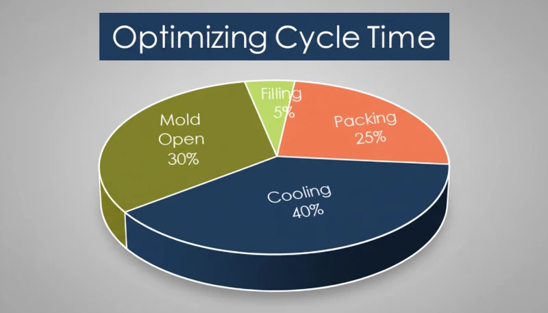
Ridurre la velocità al gate minimizza lo stress di taglio ed evita che il materiale fuso attraversi l'apertura in modo turbolento. Questa è una delle correzioni più efficaci basate sulla velocità per i difetti. stampaggio a iniezione machine. Get it right, and you get shiny, dimensionally stable parts cycle after cycle. Get it wrong, and you’ll be chasing flash, short shots, sink marks, and warpage until the end of time. In our Shanghai factory, we’ve spent 20+ years dialing in speed profiles across machines from 90T to 1850T, and this guide distills what actually matters.
- Injection speed directly controls melt flow rate, cavity pressure, and part quality
- Multi-stage speed profiles outperform single-speed filling for most parts
- Thin-walled parts demand faster speeds; thick-walled parts need slow-fast-slow curves
- Speed adjustment can solve flash, short shots, jetting, and burn marks
- Material viscosity and gate design dictate your starting speed range
What Is Injection Speed in Injection Molding?
Injection speed is the screw velocity that fills the mold cavity with molten plastic. It is usually expressed in mm/s or cm3/s and becomes the first setup lever after melt temperature, mold temperature, and clamp force are stable. If you are comparing vendors or planning procurement, our injection molding supplier sourcing guide covers RFQ preparation and supplier checks.
Injection speed is the rate at which the screw drives molten polymer into the mold cavity, measured in mm/s or cm/s. It determines how quickly the cavity fills before the material begins to solidify. On a hydraulic machine, the injection speed is controlled by the flow rate of hydraulic oil to the injection cylinder. On an all-electric machine, a servo motor drives the screw, and speed is set directly as a digital parameter.
The relationship between speed and part quality is not linear. Below a certain threshold, the melt cools too much during filling, creating weak weld lines, flow marks, and uneven density. Above another threshold, the melt enters the cavity turbulently, trapping air, causing jetting, and generating excessive shear heat that can degrade the polymer. The sweet spot — and it is different for every mold and material — is where the melt front advances steadily, fills uniformly, and packs out completely.
In practice, injection speed interacts with injection pressure, melt temperature, and mold temperature. You cannot optimize speed in isolation. But speed is usually the first parameter to tune after you have set barrel temperatures and clamp force, because its effects on surface appearance and dimensional consistency are immediate and obvious.
In our Shanghai factory, we run 47 injection molding machines ranging from 90T to 1850T. Across thousands of production runs, we have found that injection speed is the single most impactful parameter to get right during initial process setup — more so than holding pressure or cooling time for most parts.

Why Does Injection Speed Matter for Part Quality?
Injection speed is a primary control for molded part quality. It governs melt-front velocity, cavity pressure, and cooling uniformity. When the melt enters too slowly, the polymer cools before the cavity is full, causing cold slugs, weak knit lines, uneven density, and incomplete packing. When it enters too fast, the process can create jetting, air traps, flash, burn marks, and excess shear heat.
When the melt enters too fast, you get a different set of problems: jetting where the melt shoots through the gate like a fire hose instead of spreading in a smooth front, air traps from turbulent flow which cause burns and voids, flash at the parting line from the sudden pressure spike, and surface blemishes like silver streaks from moisture or gas.
The ideal speed keeps the melt front velocity constant throughout filling. Since the cross-sectional area of the cavity changes along the flow path, the screw speed needs to change too — which is exactly why multi-stage profiling1 exists. Each phase of filling demands a different speed to keep the melt front advancing at a consistent rate.
“Thin-walled parts generally require higher injection speeds than thick-walled parts.”Vero
Thin walls solidify in milliseconds. The melt must fill the entire cavity before the flow channel freezes off, requiring faster injection speeds — often 200 mm/s or higher for wall thicknesses under 0.5 mm.
“Injection speed and injection pressure are completely independent parameters.”Falso
While machine settings are separate, increasing injection speed typically raises cavity pressure due to higher volumetric flow rate and increased shear heating.
What Factors Affect Injection Speed?
The main factors affecting injection speed are material viscosity, wall thickness, gate design, flow length, and machine capability. Low-viscosity materials like PP and PA can fill at moderate speed, while PC, PMMA, and glass-filled materials need tighter control to avoid shear damage. Thin walls need faster filling before freeze-off, while thicker walls usually need a slow-fast-slow profile.
Wall thickness plays a decisive role. Thin-walled parts under 1 mm require high speed to fill before freeze-off. Thick-walled parts over 3 mm benefit from a slow-fast-slow profile to minimize sink marks and voids while still achieving reasonable cycle times. Gate type and size also matter — a pinpoint gate creates high shear at the entrance, so speed through the gate needs to be controlled, while a large edge gate can tolerate higher speeds.
Flow length is another key factor. Long flow paths require higher speed to maintain melt temperature. If the polymer cools mid-fill, you get short shots. A general rule: for every 100 mm of flow length, expect to increase speed by 10 to 20 mm/s to compensate for heat loss. Mold temperature also plays a role — a hotter mold allows slower speeds because the melt stays fluid longer.
Finally, machine capability sets the upper bound. The maximum injection speed depends on the machine hydraulic flow rate or servo motor RPM. A machine rated for 300 mm/s maximum may only deliver stable speed control between 20 and 250 mm/s. Understanding these factors together is essential for selecting the right injection speed definition2 for your specific application.
How Do You Control Injection Speed?
You control injection speed by programming hydraulic valve flow, closed-loop servo speed, or servo-electric screw movement. Proportional valve control regulates oil flow to the injection cylinder, while servo systems measure actual screw position and speed in real time. For precision parts, closed-loop control gives much better repeatability than open-loop speed settings.
Closed-loop servo control uses a high-resolution encoder on the screw to measure actual position and speed in real time. The controller adjusts the servo motor or proportional valve to match the setpoint. This gives plus or minus 0.1 percent speed accuracy and is essential for precision molding — especially medical, optical, and electronic parts where shot-to-shot consistency directly affects part quality.
Servo-electric direct drive eliminates hydraulics entirely. A ball-screw driven by a servo motor moves the injection unit. Speed control is inherently digital, with response times under 10 ms. These machines offer the most consistent shot-to-shot speed and the cleanest speed transitions between stages.
At the process level, most modern controllers let you program 5 to 10 speed stages. Each stage specifies a screw position and a target speed. The machine transitions between stages automatically as the screw advances, allowing you to slow down at the gate, speed up through the cavity, and slow down again at the end of fill — all in a single shot.
Across our 47 machines from 90T to 1850T, we use closed-loop speed control on every press. The difference between open-loop and closed-loop speed control is most visible on tight-tolerance parts — we have seen dimensional variation drop by 40 to 60 percent simply by switching to closed-loop injection speed profiling.
What Is Multi-Stage Injection Speed Profiling?
Multi-stage profiling is the practice of changing injection speed at specific points during the filling phase. Instead of running the screw at one constant speed, you program a speed curve that adapts to what is happening inside the mold. A typical 5-stage profile breaks the filling process into distinct phases, each with its own speed target.
Stage 1 is runner fill at high speed, typically 80 to 100 percent of maximum. The runner has no cosmetic or structural requirements, so speed is prioritized to minimize heat loss. Stage 2 is gate entry at slow speed, dropping to 20 to 40 percent as the melt passes through the gate. This prevents jetting, reduces shear stress, and avoids gate blush. For pinpoint gates on cosmetic parts, this stage is critical.
Stage 3 is cavity fill at fast speed, ramping back up to 60 to 90 percent once the melt has passed the gate and is spreading through the cavity. This stage typically fills to 70 to 85 percent of the part by volume. Stage 4 is the transition phase at medium speed, reducing to 30 to 50 percent as the cavity approaches full, creating a smooth transition to the packing phase and preventing overpacking near the gate.
Stage 5 is end of fill at slow speed, dropping to 10 to 20 percent for the final filling. This prevents flash, allows trapped air to escape through vents, and creates a clean transition to holding pressure. The exact speed percentages and position switchover points depend on the mold and material. Finding the optimal profile is part of the scientific molding methodology3 where you run short shots at different speeds, measure the fill pattern, and iterate.
“Slowing injection speed near the gate can help reduce jetting and gate blush defects.”Vero
Reducing speed at the gate minimizes shear stress and prevents the melt from shooting through the opening turbulently. This is one of the most effective speed-based defect fixes.
la definizione della velocità di iniezione si riferisce alla ISO 294-1:2017, che definisce la velocità di iniezione come la velocità di spostamento della vite durante la fase di riempimento dello stampaggio a iniezioneFalso
Multi-stage speed profiling consistently outperforms single-speed filling. Constant speed causes jetting at the gate, flash at end of fill, or both — depending on the chosen speed.
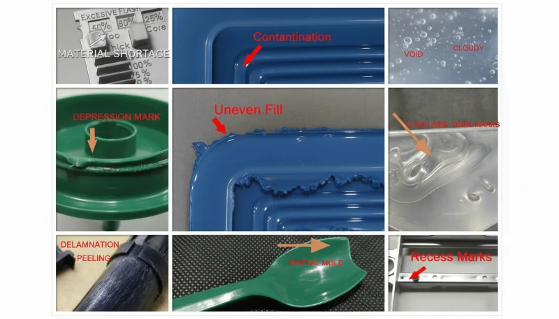
What Problems Can Speed Adjustment Solve?
Injection speed is often the first parameter to adjust when troubleshooting defects. Flash is one of the most common issues — when the melt overflows the parting line, it is usually because the cavity was overpacked at the end of fill. The solution is to reduce speed in the final stage, allowing the machine to transition smoothly to holding pressure without a pressure spike.
Short shots occur when the part is not filling completely because the melt is freezing before it reaches the end of the cavity. The solution is to increase speed during the cavity fill stage, which keeps the melt hotter and flowing further. Jetting produces worm-like lines on the part surface near the gate when the melt shoots through the gate in a narrow stream instead of spreading in a fan pattern. Slowing down at the gate entry gives the melt time to establish a proper flow front.
Burn marks appear as dark streaks or charred areas, usually near the end of fill or at blind pockets, caused by compressed superheated air. The solution is to slow down the end-of-fill speed to give air time to escape through vents before the cavity seals. Sink marks are localized depressions on the part surface above thick sections or ribs, and while sink is primarily a packing issue, faster injection speed helps by delivering hotter material to thick sections.
Flow lines are visible ripples or waviness on the part surface caused by inconsistent melt front velocity. The solution is to adjust the speed profile to maintain a steady melt front speed, typically by increasing speed as the flow path widens. Understanding material viscosity curves helps predict which speeds will produce the cleanest flow for each polymer type.
How Do You Optimize Injection Speed for Different Materials?
Material-specific speed optimization is the process of matching each speed stage to polymer viscosity, wall thickness, and heat sensitivity. Every polymer has a viscosity curve that dictates how it responds to speed and shear. The table below gives starting ranges for common materials; then refine them with short-shot studies and cavity pressure data during process setup.
| Materiale | Typical Speed Range | Key Consideration |
|---|---|---|
| PP (polipropilene) | 50-150 mm/s | Low viscosity; fast fill, moderate shear |
| PE (polietilene) | 50-120 mm/s | Similar to PP; watch for warpage in thin walls |
| PA6/PA66 (Nylon) | 60-180 mm/s | Needs fast fill to prevent premature freeze |
| ABS | 40-120 mm/s | Medium viscosity; speed affects gloss uniformity |
| PC (policarbonato) | 30-100 mm/s | High viscosity; shear-sensitive; avoid spikes at gate |
| PMMA (Acrylic) | 30-80 mm/s | Very high viscosity; optical clarity demands steady flow |
| POM (Acetal) | 50-150 mm/s | Fast crystallization; needs quick fill |
| PBT | 60-140 mm/s | Crystalline; speed affects crystallinity and shrinkage |
| Glass-filled (PA+GF) | 80-200 mm/s | High speed needed; watch fiber orientation |
| TPU | 30-80 mm/s | Low shear tolerance; slow speeds prevent degradation |
For glass-filled materials, higher injection speeds help maintain fiber length and improve mechanical properties. However, excessive speed causes fiber breakage at the gate, reducing the strengthening effect. The sweet spot is typically 100 to 150 mm/s for 30 percent glass-filled nylon. For heat-sensitive materials like PC and POM, the multi-stage approach is especially important — a sudden speed spike at the gate can generate enough shear heat to degrade the polymer.
What Are the Best Practices for Injection Speed Settings?
Based on two decades of production experience, here are the rules we follow. First, start with a decoupled molding approach — fill the cavity to 95 to 99 percent by volume using velocity control, then switch to pressure control via holding pressure. Do not try to fill and pack at the same time. Second, always profile multi-stage speed. Even for simple parts, use at minimum a 3-stage profile. The improvement in consistency is worth the setup time.
Third, use short shot analysis to find your profile. Set the machine to fill only part of the cavity, then gradually increase fill percentage while watching the flow pattern. Fourth, monitor cavity pressure, not just screw speed. What matters inside the stampo a iniezione is melt pressure and flow velocity — cavity pressure sensors give you the real picture.
Fifth, document your speed profiles. Every mold should have a documented speed curve as part of its process parameters. When you move a mold to a different machine, you will need to adjust speeds to match the new machine response characteristics. Sixth, re-validate after material lot changes — different lots of the same grade can have slightly different viscosity, and a 5 to 10 percent speed adjustment is often enough to compensate.
Come Scegliere la Velocità di Iniezione Giusta
Domande frequenti
What is a good injection speed for injection molding?
A good injection speed depends on your material and part geometry. For most thermoplastics, injection speeds range from 50 to 200 mm/s depending on viscosity and wall thickness. Thin-walled parts under 1 mm typically require speeds above 150 mm/s to fill completely before freeze-off, while thick-walled parts over 3 mm work best at 30 to 80 mm/s. Start at 50 to 70 percent of the machine maximum speed and adjust based on short shot analysis results during initial process setup.
How does injection speed affect part quality?
Injection speed directly controls melt flow rate, cavity pressure transmission, and how the part solidifies in every single molding cycle. Too slow causes short shots, weak weld lines, and incomplete filling because the melt cools before reaching the cavity end. Too fast causes flash, jetting, burn marks, and trapped air from excessive shear heating and compressed gas. The optimal speed keeps the melt front velocity constant throughout filling, producing uniform wall thickness and consistent structural integrity across the entire part.
What is multi-stage injection speed profiling?
Multi-stage profiling changes injection speed at specific screw positions during filling instead of using one constant speed throughout the entire shot. A typical five-stage profile starts with fast runner fill at 80 to 100 percent of max speed, slows at the gate to prevent jetting, accelerates for cavity fill at 60 to 90 percent, and finishes with a slow end-of-fill stage to prevent flash. This approach consistently reduces defects like flash, burn marks, and weld lines by controlling melt entry behavior.
How do you measure injection speed?
Injection speed is precisely measured as the screw displacement velocity during the filling phase, typically expressed in millimeters per second or cubic centimeters per second. Modern machines with closed-loop servo control use high-resolution encoders to track actual screw position and speed in real time, achieving accuracy within 1 percent of the set point. Most machine controllers display both instantaneous speed and average fill speed, allowing operators to verify that each stage of a multi-stage profile executes correctly during production runs.
What is the difference between injection speed and injection pressure?
Injection speed is how fast the screw moves forward during the filling phase, while injection pressure is the force pushing the melt into the cavity. Speed controls the fill phase, and pressure takes over during the packing and holding phases that follow. In decoupled molding, you deliberately separate these two phases for better process control and shot-to-shot repeatability. Setting speed too high increases pressure demands and can cause flash, while setting it too low means the cavity may not fill before the material solidifies.
Can injection speed fix flash defects?
Yes, flash is one of the most common defects resolved by adjusting injection speed in production environments. Flash occurs when the melt overflows the mold parting line due to excessive pressure or speed at the end of fill. Reducing injection speed during the final filling stage allows the mold to seal properly before pressure builds too high. Multi-stage profiling with a slow final stage at 10 to 20 percent of maximum speed is the standard corrective action for flash prevention in precision molding operations.
What injection speed should I use for ABS?
For ABS, start with a fill speed of 80 to 150 mm/s and adjust based on part geometry and wall thickness requirements. ABS has moderate viscosity and responds well to multi-stage profiling with a fast initial fill followed by a slower end-of-fill stage. Watch for gloss marks on the part surface, which indicate speed transitions that are too abrupt. If you see sink marks on thicker sections, try increasing pack pressure first rather than changing injection speed, as ABS is less sensitive to speed variations than PC.
-
multi-stage profiling: multi-stage profiling refers to the practice of varying injection speed at specific screw positions during the filling phase, a technique central to scientific and decoupled molding methodologies ↩
-
injection speed definition: injection speed definition refers to the rate at which the screw moves forward during the filling phase, measured in mm/s or cm3/s, directly controlling how quickly molten polymer fills the mold cavity ↩
-
scientific molding methodology: scientific molding methodology refers to a systematic approach to injection molding process development that uses data-driven experimentation, cavity pressure monitoring, and decoupled molding principles ↩


