 コンテンツへスキップ

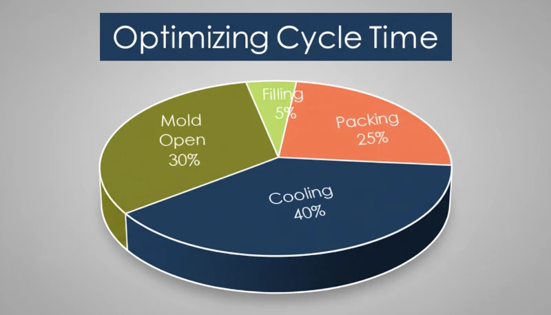
ゲートでの速度を低下させることで、せん断応力を最小限に抑え、溶融樹脂が乱流的に開口部を突き抜けるのを防ぎます。これは速度に基づく欠陥修正の中で最も効果的な方法の一つです。 射出成形 machine. Get it right, and you get shiny, dimensionally stable parts cycle after cycle. Get it wrong, and you’ll be chasing flash, short shots, sink marks, and warpage until the end of time. In our Shanghai factory, we’ve spent 20+ years dialing in speed profiles across machines from 90T to 1850T, and this guide distills what actually matters.
- Injection speed directly controls melt flow rate, cavity pressure, and part quality
- Multi-stage speed profiles outperform single-speed filling for most parts
- Thin-walled parts demand faster speeds; thick-walled parts need slow-fast-slow curves
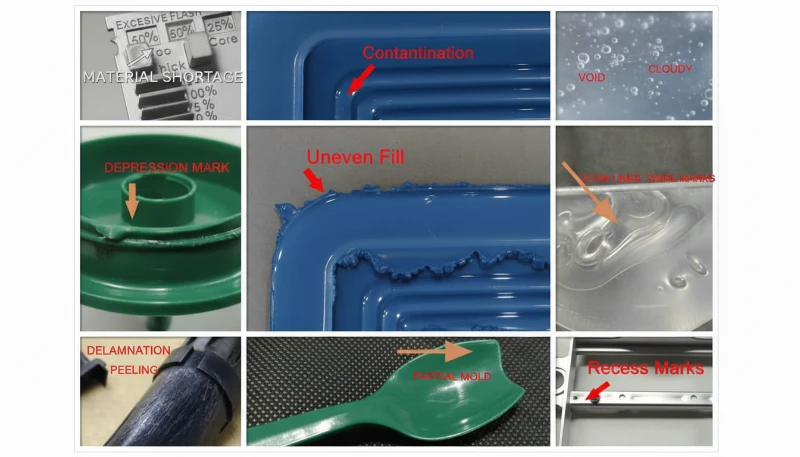
- Speed adjustment can solve flash, short shots, jetting, and burn marks
- Material viscosity and gate design dictate your starting speed range
What Is Injection Speed in Injection Molding?
射出速度は、スクリューの速度であり、溶融プラスチックを金型キャビティに充填します。通常、mm/sまたはcm3/sで表され、溶融温度、金型温度、クランプ力が安定した後の最初の設定項目となります。ベンダーを比較したり、調達を計画している場合は、当社の injection molding supplier sourcing guide RFQ準備とサプライヤーチェックをカバーします。
射出速度は、スクリューが溶融ポリマーを金型キャビティに押し込む速度であり、mm/sまたはcm/sで測定されます。これは、材料が固化し始める前にキャビティが充填される速さを決定します。油圧成形機では、射出速度は射出シリンダーへの作動油の流量によって制御されます。オール電動成形機では、サーボモーターがスクリューを駆動し、速度はデジタルパラメータとして直接設定されます。
The relationship between speed and part quality is not linear. Below a certain threshold, the melt cools too much during filling, creating weak weld lines, flow marks, and uneven density. Above another threshold, the melt enters the cavity turbulently, trapping air, causing jetting, and generating excessive shear heat that can degrade the polymer. The sweet spot — and it is different for every mold and material — is where the melt front advances steadily, fills uniformly, and packs out completely.
In practice, injection speed interacts with injection pressure, melt temperature, and mold temperature. You cannot optimize speed in isolation. But speed is usually the first parameter to tune after you have set barrel temperatures and clamp force, because its effects on surface appearance and dimensional consistency are immediate and obvious.
In our Shanghai factory, we run 47 injection molding machines ranging from 90T to 1850T. Across thousands of production runs, we have found that injection speed is the single most impactful parameter to get right during initial process setup — more so than holding pressure or cooling time for most parts.

Why Does Injection Speed Matter for Part Quality?
射出速度は成形部品の品質を制御する主要な要素です。それはメルトフロント速度、キャビティ内圧力、冷却均一性を支配します。メルトが遅すぎて流入すると、ポリマーはキャビティが満たされる前に冷却され、コールドスラグ、弱いニットライン、不均一な密度、不完全なパッキングを引き起こします。速すぎて流入すると、ジェッティング、エアトラップ、フラッシュ、焼け跡、過剰なせん断熱が発生する可能性があります。
When the melt enters too fast, you get a different set of problems: jetting where the melt shoots through the gate like a fire hose instead of spreading in a smooth front, air traps from turbulent flow which cause burns and voids, flash at the parting line from the sudden pressure spike, and surface blemishes like silver streaks from moisture or gas.
The ideal speed keeps the melt front velocity constant throughout filling. Since the cross-sectional area of the cavity changes along the flow path, the screw speed needs to change too — which is exactly why multi-stage profiling1 exists. Each phase of filling demands a different speed to keep the melt front advancing at a consistent rate.
“Thin-walled parts generally require higher injection speeds than thick-walled parts.”真
Thin walls solidify in milliseconds. The melt must fill the entire cavity before the flow channel freezes off, requiring faster injection speeds — often 200 mm/s or higher for wall thicknesses under 0.5 mm.
“Injection speed and injection pressure are completely independent parameters.”偽
While machine settings are separate, increasing injection speed typically raises cavity pressure due to higher volumetric flow rate and increased shear heating.
What Factors Affect Injection Speed?
射出速度に影響を与える主な要因は、材料粘度、肉厚、ゲート設計、流動長、および成形機能力です。PPやPAなどの低粘度材料は中程度の速度で充填できますが、PC、PMMA、ガラス充填材料はせん断損傷を避けるために厳密な制御が必要です。薄肉部は凍結前に高速充填が必要であり、厚肉部は通常、低速-高速-低速のプロファイルが必要です。
Wall thickness plays a decisive role. Thin-walled parts under 1 mm require high speed to fill before freeze-off. Thick-walled parts over 3 mm benefit from a slow-fast-slow profile to minimize sink marks and voids while still achieving reasonable cycle times. Gate type and size also matter — a pinpoint gate creates high shear at the entrance, so speed through the gate needs to be controlled, while a large edge gate can tolerate higher speeds.
Flow length is another key factor. Long flow paths require higher speed to maintain melt temperature. If the polymer cools mid-fill, you get short shots. A general rule: for every 100 mm of flow length, expect to increase speed by 10 to 20 mm/s to compensate for heat loss. Mold temperature also plays a role — a hotter mold allows slower speeds because the melt stays fluid longer.
Finally, machine capability sets the upper bound. The maximum injection speed depends on the machine hydraulic flow rate or servo motor RPM. A machine rated for 300 mm/s maximum may only deliver stable speed control between 20 and 250 mm/s. Understanding these factors together is essential for selecting the right injection speed definition2 for your specific application.
How Do You Control Injection Speed?
射出速度は、油圧バルブの流量制御、閉ループサーボ速度制御、またはサーボ電動スクリュー駆動をプログラムすることで制御します。比例制御バルブは射出シリンダーへの油流量を調整し、サーボシステムは実際のスクリュー位置と速度をリアルタイムで計測します。精密部品の場合、閉ループ制御は開ループ速度設定よりもはるかに優れた再現性を提供します。
Closed-loop servo control uses a high-resolution encoder on the screw to measure actual position and speed in real time. The controller adjusts the servo motor or proportional valve to match the setpoint. This gives plus or minus 0.1 percent speed accuracy and is essential for precision molding — especially medical, optical, and electronic parts where shot-to-shot consistency directly affects part quality.
Servo-electric direct drive eliminates hydraulics entirely. A ball-screw driven by a servo motor moves the injection unit. Speed control is inherently digital, with response times under 10 ms. These machines offer the most consistent shot-to-shot speed and the cleanest speed transitions between stages.
At the process level, most modern controllers let you program 5 to 10 speed stages. Each stage specifies a screw position and a target speed. The machine transitions between stages automatically as the screw advances, allowing you to slow down at the gate, speed up through the cavity, and slow down again at the end of fill — all in a single shot.
Across our 47 machines from 90T to 1850T, we use closed-loop speed control on every press. The difference between open-loop and closed-loop speed control is most visible on tight-tolerance parts — we have seen dimensional variation drop by 40 to 60 percent simply by switching to closed-loop injection speed profiling.
What Is Multi-Stage Injection Speed Profiling?
Multi-stage profiling is the practice of changing injection speed at specific points during the filling phase. Instead of running the screw at one constant speed, you program a speed curve that adapts to what is happening inside the mold. A typical 5-stage profile breaks the filling process into distinct phases, each with its own speed target.
Stage 1 is runner fill at high speed, typically 80 to 100 percent of maximum. The runner has no cosmetic or structural requirements, so speed is prioritized to minimize heat loss. Stage 2 is gate entry at slow speed, dropping to 20 to 40 percent as the melt passes through the gate. This prevents jetting, reduces shear stress, and avoids gate blush. For pinpoint gates on cosmetic parts, this stage is critical.
Stage 3 is cavity fill at fast speed, ramping back up to 60 to 90 percent once the melt has passed the gate and is spreading through the cavity. This stage typically fills to 70 to 85 percent of the part by volume. Stage 4 is the transition phase at medium speed, reducing to 30 to 50 percent as the cavity approaches full, creating a smooth transition to the packing phase and preventing overpacking near the gate.
Stage 5 is end of fill at slow speed, dropping to 10 to 20 percent for the final filling. This prevents flash, allows trapped air to escape through vents, and creates a clean transition to holding pressure. The exact speed percentages and position switchover points depend on the mold and material. Finding the optimal profile is part of the scientific molding methodology3 where you run short shots at different speeds, measure the fill pattern, and iterate.
“Slowing injection speed near the gate can help reduce jetting and gate blush defects.”真
Reducing speed at the gate minimizes shear stress and prevents the melt from shooting through the opening turbulently. This is one of the most effective speed-based defect fixes.
射出速度の定義:偽
Multi-stage speed profiling consistently outperforms single-speed filling. Constant speed causes jetting at the gate, flash at end of fill, or both — depending on the chosen speed.
What Problems Can Speed Adjustment Solve?
Injection speed is often the first parameter to adjust when troubleshooting defects. Flash is one of the most common issues — when the melt overflows the parting line, it is usually because the cavity was overpacked at the end of fill. The solution is to reduce speed in the final stage, allowing the machine to transition smoothly to holding pressure without a pressure spike.
Short shots occur when the part is not filling completely because the melt is freezing before it reaches the end of the cavity. The solution is to increase speed during the cavity fill stage, which keeps the melt hotter and flowing further. Jetting produces worm-like lines on the part surface near the gate when the melt shoots through the gate in a narrow stream instead of spreading in a fan pattern. Slowing down at the gate entry gives the melt time to establish a proper flow front.
Burn marks appear as dark streaks or charred areas, usually near the end of fill or at blind pockets, caused by compressed superheated air. The solution is to slow down the end-of-fill speed to give air time to escape through vents before the cavity seals. Sink marks are localized depressions on the part surface above thick sections or ribs, and while sink is primarily a packing issue, faster injection speed helps by delivering hotter material to thick sections.
Flow lines are visible ripples or waviness on the part surface caused by inconsistent melt front velocity. The solution is to adjust the speed profile to maintain a steady melt front speed, typically by increasing speed as the flow path widens. Understanding material viscosity curves helps predict which speeds will produce the cleanest flow for each polymer type.
How Do You Optimize Injection Speed for Different Materials?
材料固有の速度最適化は、各速度段階をポリマーの粘度、肉厚、熱感受性に合わせるプロセスです。すべてのポリマーには、速度とせん断にどのように反応するかを決定する粘度曲線があります。以下の表は一般的な材料の開始範囲を示しています。その後、プロセス設定時のショートショット試験とキャビティ内圧データを用いて調整します。
| 素材 | Typical Speed Range | 稼働中のプラスチック射出成形機が部品を生産中 |
|---|---|---|
| PP(ポリプロピレン) | 50-150 mm/s | Low viscosity; fast fill, moderate shear |
| PE(ポリエチレン) | 50-120 mm/s | Similar to PP; watch for warpage in thin walls |
| PA6/PA66 (Nylon) | 60-180 mm/s | Needs fast fill to prevent premature freeze |
| ABS | 40-120 mm/s | Medium viscosity; speed affects gloss uniformity |
| PC(ポリカーボネート) | 30-100 mm/s | High viscosity; shear-sensitive; avoid spikes at gate |
| PMMA (Acrylic) | 30-80 mm/s | Very high viscosity; optical clarity demands steady flow |
| POM (Acetal) | 50-150 mm/s | Fast crystallization; needs quick fill |
| PBT | 60-140 mm/s | Crystalline; speed affects crystallinity and shrinkage |
| Glass-filled (PA+GF) | 80-200 mm/s | High speed needed; watch fiber orientation |
| TPU | 30-80 mm/s | Low shear tolerance; slow speeds prevent degradation |
For glass-filled materials, higher injection speeds help maintain fiber length and improve mechanical properties. However, excessive speed causes fiber breakage at the gate, reducing the strengthening effect. The sweet spot is typically 100 to 150 mm/s for 30 percent glass-filled nylon. For heat-sensitive materials like PC and POM, the multi-stage approach is especially important — a sudden speed spike at the gate can generate enough shear heat to degrade the polymer.
What Are the Best Practices for Injection Speed Settings?
Based on two decades of production experience, here are the rules we follow. First, start with a decoupled molding approach — fill the cavity to 95 to 99 percent by volume using velocity control, then switch to pressure control via holding pressure. Do not try to fill and pack at the same time. Second, always profile multi-stage speed. Even for simple parts, use at minimum a 3-stage profile. The improvement in consistency is worth the setup time.
Third, use short shot analysis to find your profile. Set the machine to fill only part of the cavity, then gradually increase fill percentage while watching the flow pattern. Fourth, monitor cavity pressure, not just screw speed. What matters inside the 射出成形金型 is melt pressure and flow velocity — cavity pressure sensors give you the real picture.
Fifth, document your speed profiles. Every mold should have a documented speed curve as part of its process parameters. When you move a mold to a different machine, you will need to adjust speeds to match the new machine response characteristics. Sixth, re-validate after material lot changes — different lots of the same grade can have slightly different viscosity, and a 5 to 10 percent speed adjustment is often enough to compensate.
射出速度に関する最も一般的な質問は何ですか?
よくある質問
射出成形における適切な射出速度とは何ですか?
適切な射出速度は、材料と製品形状によって異なります。ほとんどの熱可塑性樹脂では、粘度と肉厚に応じて射出速度は50~200 mm/sの範囲になります。1 mm未満の薄肉製品は、凍結前に完全に充填するために通常150 mm/s以上の速度が必要です。一方、3 mmを超える厚肉製品では、30~80 mm/sの速度が最適です。初期プロセス設定時には、機械の最大速度の50~70%から開始し、ショートショット解析の結果に基づいて調整してください。
射出速度は製品品質にどのような影響を与えますか?
射出速度は、メルト流量、キャビティ内圧力の伝達、および部品が各成形サイクルで固化する方法を直接制御します。遅すぎると、メルトがキャビティ端に到達する前に冷却されるため、ショートショット、弱い溶着ライン、不完全充填を引き起こします。速すぎると、過剰なせん断加熱と圧縮ガスにより、フラッシュ、ジェッティング、焼け跡、エアトラップを引き起こします。最適な速度は、充填全体を通じてメルトフロント速度を一定に保ち、均一な肉厚と部品全体で一貫した構造的完全性を生み出します。
マルチステージ射出速度プロファイリングとは何ですか?
マルチステージプロファイリングは、一つの一定速度を全ショットで使用する代わりに、充填中の特定のスクリュー位置で射出速度を変更します。典型的な5段階プロファイルは、最大速度の80〜100%での高速ランナー充填で開始し、ゲートでジェッティングを防ぐために減速し、キャビティ充填のために60〜90%で加速し、フラッシュを防ぐための低速の充填終了段階で終了します。このアプローチは、メルトの流入挙動を制御することで、フラッシュ、焼け跡、溶着ラインなどの不良を一貫して低減します。
射出速度はどのように測定しますか?
射出速度は、充填段階におけるスクリューの変位速度として正確に測定され、通常は毎秒ミリメートルまたは毎秒立方センチメートルで表されます。閉ループサーボ制御を備えた最新の成形機は、高分解能エンコーダーを使用して実際のスクリュー位置と速度をリアルタイムで追跡し、設定値の1%以内の精度を達成します。ほとんどの成形機コントローラーは、瞬時速度と平均充填速度の両方を表示するため、生産運転中に多段プロファイルの各段階が正しく実行されていることをオペレーターが確認できます。
What is the difference between injection speed and injection pressure?
射出速度は充填段階でのスクリューの前進速度であり、射出圧力はメルトをキャビティに押し込む力です。速度は充填段階を制御し、圧力はそれに続くパッキングおよび保圧段階を引き継ぎます。デカップル成形では、より良いプロセス制御とショット間の再現性を得るために、これら2つの段階を意図的に分離します。速度を高く設定しすぎると圧力要求が増加しフラッシュの原因となり、低く設定しすぎると材料が固化する前にキャビティが充填されない可能性があります。
射出速度はフラッシュ不良を修正できますか?
はい、フラッシュは生産環境で射出速度を調整することで解決される最も一般的な欠陥の一つです。フラッシュは、充填終了時に過剰な圧力や速度によって溶融樹脂が金型のパーティングラインから溢れ出ることで発生します。最終充填段階で射出速度を低下させることで、圧力が高くなりすぎる前に金型が適切にシールされるようになります。最大速度の10~20%の低速最終段階を設定した多段プロファイリングは、精密成形作業におけるフラッシュ防止の標準的な是正措置です。
ABSにはどの射出速度を使用すべきですか?
ABSの場合、充填速度を80〜150 mm/sで開始し、部品形状と肉厚要件に基づいて調整します。ABSは中程度の粘度を持ち、高速の初期充填に続く低速の充填終了段階を伴うマルチステージプロファイリングに適しています。部品表面の光沢跡に注意してください。これは速度遷移が急激すぎることを示しています。肉厚部分にシンクマークが見られる場合は、ABSはPCよりも速度変動の影響を受けにくいため、射出速度を変更する前にパック圧力を上げてみてください。
-
multi-stage profiling:マルチステージプロファイリングとは、充填段階で特定のスクリュー位置で射出速度を変化させる手法を指し、科学的およびデカップル成形方法論の中核となる技術です ↩
-
injection speed definition:射出速度の定義は、充填段階でのスクリューの前進速度を指し、mm/sまたはcm3/sで測定され、溶融ポリマーが金型キャビティを充填する速さを直接制御します ↩
-
scientific molding methodology:科学的成形方法論とは、データ駆動型実験、キャビティ内圧モニタリング、デカップル成形の原則を使用する、射出成形プロセス開発への体系的なアプローチを指します ↩


