 Skip to content

Introduction: Polycarbonate (PC) is a super cool plastic that’s really good at a lot of things. It’s super clear and tough, and it doesn’t get all weird when you put weight on it. It’s also safe to use, can handle hot and cold temperatures, and doesn’t change shape when you don’t want it to. Plus, it’s great at keeping electricity in its place and can handle the weather. That’s why people use it for all kinds of stuff, like making things that measure things, lights, electronics, home stuff, and packages.
PC is a linear polymer that has benzene rings, isopropyl groups, and acetic bonds in the main chain structure of the molecule. This structure makes it both rigid and flexible, as well as having good high temperature resistance. However, it also has shortcomings such as high melt viscosity and sensitivity to moisture, which brings certain difficulties to injection molding.
The processing technology characteristics of PC are that it has no obvious melting point. The modified PC has high melt viscosity at normal processing temperature, i.e., 230-320℃. The viscosity is less sensitive to shear rate and more sensitive to temperature, which is similar to Newtonian fluid behavior; it is sensitive to moisture, and the resin is easily hydrolyzed at high temperature; the product is prone to internal stress, etc.
It can be seen that PC is a plastic that is difficult to process. Therefore, in the actual production process, we encounter many problems. For example, in the polycarbonate injection molding process, the quality of the weld lines is affected by the material temperature and wall thickness, and sink marks may be defects caused by improper use of these factors . In this article, several common injection molding defects are analyzed and discussed.
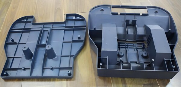
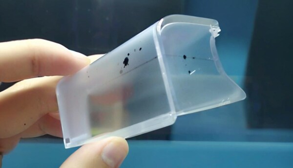
Product Discoloration, Blackening, Yellow Streaks and Black Spots
Defect Analysis
PC has good heat resistance. When processing ordinary PC materials, its melting temperature can be set at 240℃-300℃. Even if it stays for a long time, it will generally not decompose. But why does discoloration often occur when producing some electrical products?
That’s because the market competition is fierce now. In order to reduce production costs, most manufacturers use PC modified materials or recycled materials when producing medium and low-end electrical products. Some manufacturers even use materials mixed with flame retardants, fillers, etc. Because these materials have mixed flows and high plasticization requirements, it is more difficult to control the process, resulting in various problems.
Solutions
To address the aforementioned issue, we need to take into account and come up with remedies from the following perspectives:
Process Conditions
The main thing to consider is the melting temperature. Generally, the temperature of the barrel should be reduced step by step, especially the temperature of the first two sections. Different temperatures are used for different materials.
For example, when polyethylene (PE) is used to modify PC to produce large electrical appliances, the temperature of the barrel should generally be controlled at around 230°C; when ABS or PS is used to modify PC to produce small electrical components such as switches and sockets, the temperature of the barrel should generally be controlled at around 250°C; and when PBT is used to modify PC to produce lighting products, the temperature of the barrel should generally be controlled at around 280°C.
Of course, the final selection of molding temperature must also take into account aspects such as product shape, size, mold structure, and product performance requirements. Secondly, the raw materials should be fully dried to reduce the possibility of trace moisture catalytic cracking of the hot melt.

Also, if the screw speed is too fast, the back pressure is too high, the injection rate is too fast, and the nozzle hole, runner, and gate size are too small, the melt will generate high shear heat, causing PC to have melt fracture, and it is easy for the gas in the mold cavity to not be discharged in time, causing local burns and blackening of the product.
Equipment
Because PC melt has high viscosity and poor fluidity, it requires high injection pressure. PC melt has strong bonding force with metal, and its decomposition products are highly corrosive to metal. Therefore, when selecting processing equipment, it is required to use small or specially designed, chrome-plated screws. The plasticizing system is not allowed to have dead corners, dead material, gaps, cracks, etc.
If the process conditions are good, but the melt is discolored during air injection, it means that there is a problem with the plasticizing system. You need to check the plasticizing system one by one, starting from the nozzle, to the nozzle flange, three small parts, screw, and barrel.Sometimes the product will change color in two or three molds at a time. This is mostly related to the existence of dead material in the plasticizing system.

When the PC decomposition products exceed a certain amount, they have their own catalytic effect, causing a large area of melt decomposition, especially plastics with flame retardants added. This requires finding dead material points such as screw sticking, stock, barrel sticking, etc., which need to be solved by cleaning, repairing, and polishing.
Materials and Operation Methods
If you see black spots when you turn on the machine, it’s probably because of the material left in the barrel. So you need to pay attention to the operation method. If you’re using PC as the material in the barrel before you turn on the machine, you need to clean the barrel 3-4 times with new material at the molding temperature (injection into the air).
If you’re using other materials, especially materials with poor thermal stability like PVC, POM, etc., you can’t increase the temperature when you turn on the machine, and you can’t clean the barrel with PC materials. You can only use materials with good thermal stability like PS, PE, etc. to clean the material at a lower temperature.

After purging, raise the barrel temperature to the normal processing temperature of PC, and then purge it with PC material before processing. During processing, if production needs to be temporarily stopped, the barrel temperature must be lowered to below 160°C for insulation (because the glass transition temperature of PC is 160°C), so as to avoid discoloration due to material decomposition over time.
When the production task is completed, the barrel can be purged with materials with good thermal stability such as PS and PE, and the machine can be stopped after emptying.If there is discoloration during production, first check if there is a problem with the material. Are other materials and foreign matter mixed in? Is there a problem with the quality of the new material? Is the gate material qualified? Is the mixing method correct?
Once you’ve ruled out all the other possibilities, look for other reasons. Another reason is that the environmental pollution is relatively serious, such as a lot of dust floating in the air, the mold is contaminated, the self-baking hopper filter does not work and absorbs more dust particles.
This requires the processing workshop to be kept clean at all times, clean and tidy. It is best to cover the hopper air inlet and outlet with fine gauze, which is very necessary when processing transparent products.
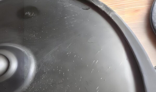
Silver Streaks, Bubbles, and Vacuum Bubbles Appear on the Product
Defect Analysis
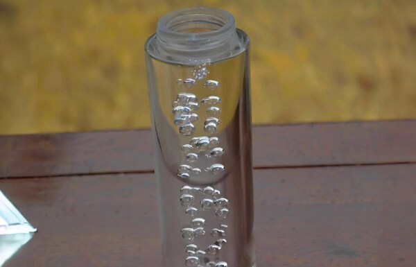
Silver streaks, bubbles, and vacuum bubbles on the product are common defects of PC materials. There are many causes of these defects, so it is difficult to judge and eliminate them.Silver streaks (or gas streaks) are defects on the surface of a product caused by gas interference during the filling process. The gases involved are mainly water vapor, air, decomposition gas, and solvent gas, with water vapor, decomposition gas, and air being the most common.
When the pressure in the mold exceeds a certain limit, the mold cavity loses pressure after injection molding, and the gas near the surface of the product will escape, leaving behind a series of small and large bubbles that sparkle under the light, following the direction of the material flow. This is what we call silver streaks or gas streaks.
Actually, gas is always present during the injection molding process, and a lot of it stays in the plastic. When the pressure in the mold is high enough and the gas content doesn’t go over a certain limit, the gas dissolves into the plastic in a dispersed state.But when the pressure in the mold isn’t high enough and the gas content goes over a certain limit, these gases come out of the molten plastic and go to the surface of the product to make silver streaks. They get stuck in the thick wall and become bubbles.
Whether it’s the silver streaks on the surface of the product or the bubbles in the wall of the product, it may be the result of the action of one of the four gases or the result of the joint action of several gases. It has a lot to do with factors such as raw materials, molds, plasticizing systems, adjustment of process parameters, and even weather changes (especially humidity changes). So this problem is more complicated. But in any case, the focus of the problem and the solution should be focused on the gas, that is, how to control the gas content.
Water Vapor
If you see bubbles randomly scattered on the surface of the product, it’s probably water vapor.PC hot melt material is very sensitive to moisture and requires a moisture content of less than 0.02%. So, to control the moisture content, the material must be fully dried. Generally, the drying temperature of PC material is about 120℃ and the drying time is about 4h.

The time should not be too long. If it exceeds 10h, the material is easy to deteriorate, especially the material with flame retardant added should not be dried for too long. The best drying method is the dehumidification dryer, which has no effect on the material. To check whether the drying effect is good, you can use the air injection method to see whether the ejected material is continuous, smooth and does not emit white gas.
Air
If the bubble particles are super fine and dense, they are mainly distributed around the product gate, forming radiant or fan-shaped patterns, which is mostly caused by air.The source of air is:
Air Entrained in the Material.
When there are more gate materials and the particle sizes vary greatly, it is easy to entrain air. Therefore, when using gate materials, it is best to screen out the powder. If the back pressure is too low during melting and the screw speed is too high, the screw will retreat too fast, and the air will be easily pushed to the front end of the barrel with the material.
Therefore, it is generally recommended to extend the melting time as much as possible during the cooling time, which is very helpful to improve the plasticization quality.
If the temperature of the material discharge section is not well controlled, the temperature is too high, which will cause part of the material to melt prematurely and block the passage for the air to exit the discharge port; if the temperature is too low, the preheating is insufficient, causing part of the pellets to enter the homogenization section and be wrapped in air.

In addition, too much looseness will also inhale air. In the above situation, adjusting the screw speed, back pressure and back pressure can generally solve the problem.
Exhaust During Mold Filling.
To make PC materials with high melt viscosity fill the mold smoothly, you usually have to increase the melt temperature and injection pressure. When the melt is at high temperature and high pressure, if you inject it quickly, it will suddenly go through the narrow flow channel and gate into the mold cavity with a lot of free space.

In this way, the gas that comes out of the melt will take the air in the flow channel and the mold cavity with it, and you’ll get a high-speed injection state. On the surface of the condensed plastic, you’ll see traces of the air flow that’s been dispersed, and that’s called gas pattern.
Also, if there are a lot of corners in the mold cavity, the thickness difference is too big, or there are a lot of inserts and the gate position is not right, the melt will rush into the mold cavity, stir up the air in the mold to form a vortex, and gas patterns will form in certain parts, such as the switch and socket panel of molded electrical products.

Because its sockets, interfaces, and switches are concentrated in one part, this situation often occurs. The solution to this defect is to modify the mold, strengthen the mold exhaust, and optimize the gate position on the one hand; on the other hand, reduce the filling rate, especially the injection rate of the gas pattern part.
Decomposition Gas
Since PC materials need to be molded at high temperatures, some decomposition is inevitable. But how to avoid large-scale decomposition and how to remove gas is worth discussing.Similar to the discoloration mentioned above, the main reason for the generation of decomposition gas is that the melt temperature is too high. For example, the barrel temperature is set too high, or the heating coil of the barrel is out of control.
The heating coil should be checked section by section starting from the nozzle to reduce the barrel temperature; the melt stays in the barrel for too long (such as using large equipment to produce small products, the amount of cushion is too large), the molding cycle is too long, or the stale material in the barrel and the material stored in the dead corner are decomposed due to long-term heating.

Or the melt is subjected to strong shear in the barrel, such as the compression ratio of the screw is too large, the screw speed is too high, and the back pressure is too large, which will also cause decomposition.
Also, if the nozzle hole is too small, the mold gate and runner are too small, and the cavity resistance is large, the melt passing through can be decomposed due to local overheating caused by friction. Therefore, when processing PC materials, the nozzle hole, gate, and runner dimensions are large, the exhaust groove should be deep, and it is not suitable to make thin-walled products.
Another important reason is that the PC itself is of poor quality and easy to decompose. This is often ignored by users, and the problem is pushed to the mold and processing equipment, so that the correct solution to the problem cannot be found.
Solvent Gas
Solvent gas is mainly related to the quality of operation in production, such as unclean barrel cleaning and excessive addition of additives. Most of the solvent gas can be removed by sufficient drying, and it does not have a great impact on gas marks.
Sometimes it is hard to tell if the bubble points inside transparent products are bubbles or vacuum bubbles. Generally, if the bubble points are found when the mold is opened, and the volume doesn’t change much after being stored for a while, it is a bubble caused by gas interference; if it appears and gets bigger during demolding and cooling process, it is a vacuum bubble.
Vacuum bubbles form when there isn’t enough material or pressure when the mold is filled. The mold cools quickly, so the molten material touching the mold wall solidifies first. Then, the material in the middle cools and shrinks, which makes the volume shrink and creates a hollow spot, or bubble.
Solutions
Increase Injection Pressure, Injection Time, and Material Quantity
Adjust melt temperature: When the vacuum bubble is far away from the gate, increase the melt temperature to make the melt flow smoothly, and the pressure can be transmitted to the part far away from the gate; when the vacuum bubble is near the gate, the melt temperature can be lowered to reduce shrinkage;
Appropriately increase the mold temperature, especially the mold temperature of the local part where the vacuum bubble is formed.
Put the gate at the thick wall part of the product to improve the flow conditions of the nozzle, runner and gate and the exhaust conditions of the mold; shorten the cooling time of the product in the mold, and if necessary, put the product into hot water for slow cooling; products molded with point gates can be molded slowly and at low temperature to solve the vacuum bubble problem, and the runner size can be increased when there are vacuum bubbles on the runner.

In addition, it was found during the production process that bubbling occurred in the thick-walled part of the PC product soon after demolding. This was caused by insufficient cooling, which caused the internal gas of the PC to expand.
Generally, measures such as extending the cooling time, enhancing the cooling effect, increasing the holding pressure and time, and delaying the decomposition of PC can be used to solve the problem.
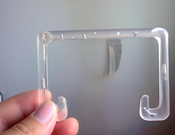
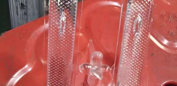
“Fingerprint” on the Product
Defect Analysis
Because PC melt has a high viscosity and poor fluidity, it is more likely to have a “fingerprint” phenomenon.”Fingerprint” is called that because it looks like a human fingerprint. It is sometimes called ripples, vibration patterns, or vibration patterns, which means that its patterns are like those formed by a stone falling on a calm water surface. The main reason for its occurrence is that the viscosity of the PC melt is too high.
When the injection pressure and injection rate are low, the melt fills the mold in the form of stagnant flow. Once the front molten material contacts the cold mold surface, it quickly condenses and shrinks, and the hot molten material at the back expands the shrunken cold material under the pressure and continues to move forward. This process is carried out alternately, forming vertical ripple lines in the direction of material flow.
Solutions
Increase the Temperature
To increase the temperature, mainly increase the temperature of the nozzle, the front end temperature of the barrel, and the temperature of the mold, especially the temperature where the corrugation is generated. This is to reduce the melt viscosity of PC and improve the melt fluidity. In addition, if the product is relatively precise and has strict requirements on appearance, it is necessary to add a mold temperature controller to accurately control the mold temperature at around 120℃.
Increase the Injection Rate and Injection Pressure
To increase the injection rate and injection pressure is mainly to increase the melt flow rate at the “fingerprint” and prevent the melt from flowing in the form of stagnant flow. If the “fingerprint” is generated in the center of the product or far away from the gate position, multi-stage injection should be used to adjust the injection rate section by section.
Modify the Mold
Change the mold mainly to reduce the resistance of the melt during filling, such as increasing the size of the runner and gate; pay attention to the polishing of the nozzle hole and runner; increase the exhaust groove and slot; set inserts and ejector air guide devices; improve the exhaust condition of the mold; set a sufficiently large cold material trap to reduce the flow resistance of the front cold material.
Turbulence Marks Appear on the Product
Defect Analysis
Turbulence marks are the irregular flow lines that are centered on the gate in PC products. Unlike the “fingerprint” line, turbulence marks appear in the direction of material flow rather than perpendicular to the direction of material flow. The reason may be that the molten material injected into the mold cavity is subjected to a large impact, which makes it sticky and slippery on the cold mold.

Solutions
Bump up the melt temperature to stop the melt from cooling too fast; bump up the mold temperature, especially in the area where the flow marks are, to stop the melt from sliding around in the mold before it’s ready; use multi-stage injection to slow down the injection rate and pressure in the area where the flow marks are; change the gate location to change the way the melt flows;
Make sure the cold material is packed tightly so it doesn’t slide around in the mold; Use materials that flow well so the molten material fills the mold smoothly.
Cold Material Spots Appear in the Product
Defect Analysis
Cold material spots are a common defect in PC product gates. This is when the product has foggy or bright spots near the gate, or a curved scar like an earthworm sticking to the surface of the product from the gate.
The main reason for its formation is the advancement of the cold material at the front of the molten material entering the mold cavity or the cold material squeezed into the mold cavity later due to excessive pressure holding. The front material transfers heat because the nozzle contacts the cold template or the cooling effect of the runner. When entering the mold cavity, there is the push of the hot melt, so the cold material spots are formed.

Cold material spots will be spread out on thinner products and become smoke-like or paste-like turbid spots, while on free-flowing thick-walled products, a curved scar shaped like an earthworm will be left. As for the cold material spots formed by excessive pressure holding, it is caused by the long pressure holding time. When the pressure holding pressure is too high, the cold material on the runner and gate continues to be squeezed into the product. This kind of cold material spot often forms a circular bright spot in a small area near the gate.
Another type is that the molten material quickly squeezes into a small gate and causes melt rupture around the gate, or smoke-like or light-like bright spots appear at the gate due to the interference of the gas in the mold. Cold material spots not only damage the apparent quality of the product, but also affect the effect of subsequent processes such as spraying or electroplating, and also reduce the mechanical strength of the product to varying degrees.
Solutions
Increase the temperature of the barrel and nozzle, and increase the temperature of the mold to reduce the impact of cold material; slow down the injection rate and increase the injection pressure to avoid melt fracture or interference from gas in the mold; adjust the injection time and holding time to avoid overfilling; reasonable mold gate design can reduce or avoid the formation of cold material spots in advance.

The traditional and effective method is to open a cold material well at the end of the flow channel so that the front material is trapped in the well and does not enter the mold cavity. In addition to setting up a cold material well, some molds also need to consider the rationality of the form, size and position of the gate; strengthen mold exhaust; remove pollutants in the material, strengthen the drying effect of the material, reduce or replace the lubricant, and use as little release agent as possible.
Internal Stress of Transparent Products
Defect Analysis
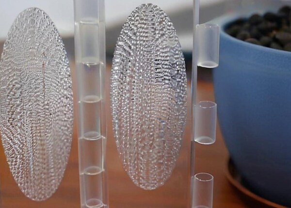
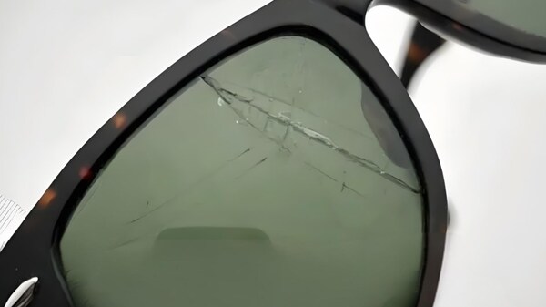
When making PC transparent products like sunglasses, windshields, eye masks, and other parts, you often find that the products are deformed, astigmatic, have poor transparency, and crack. This is mainly due to the internal stress inside the product. In fact, there is also internal stress inside opaque products, but it is not obvious.
Internal stress is the stress that happens inside the plastic because of bad molding, temperature changes, and so on, without any external force. It’s when the plastic molecules get stretched out and then freeze in place in the product. The internal stress in plastic products can mess up the mechanical properties and performance of the products, like making them warp, deform, and even get little cracks; it can make the products look bad and turn them cloudy.

Internal stress can also cause injection molded products to have higher mechanical properties in the flow direction, but lower strength in the direction perpendicular to the flow, resulting in uneven product performance, which affects product use. In particular, when the product is heated or in contact with organic solvents, it will accelerate product cracking.
The internal stress of PC products is mainly caused by orientation stress and temperature stress, and sometimes it is related to improper demolding.
Orientation Stress
It’s easy to create internal stress after the macromolecules inside the injection molded product are oriented, causing stress concentration. During injection molding, the melt cools rapidly, and the melt viscosity is higher at a lower temperature. The oriented molecules can’t fully relax. The internal stress generated in this way affects the mechanical properties and dimensional stability of the product. Therefore, melt temperature has the greatest influence on orientation stress. When the melt temperature is increased, the melt viscosity decreases, and thus the shear stress and orientation decrease.
Also, the relaxation of orientation stress is higher at high melt temperature, but when the viscosity decreases, the pressure transmitted to the mold cavity by the injection molding machine screw increases, which may increase the shear rate and lead to an increase in orientation stress. If the holding time is too long, the orientation stress increases; increasing the injection pressure will also cause an increase in orientation stress due to the increase in shear stress and shear rate. The thickness of the product also affects the internal stress.
The orientation stress decreases with the increase of the thickness of the product, because the thick-walled product cools slowly, the melt cools and relaxes for a long time in the mold cavity, and the oriented molecules have sufficient time to return to the random state. If the mold temperature is high and the melt cools slowly, the orientation stress can be reduced.
Temperature Stress
When you inject plastic, the temperature difference between the melt temperature and the mold temperature is big, so the melt near the mold wall cools faster, which makes the stress uneven in the product. Because PC has a big specific heat capacity and a small thermal conductivity, the surface of the product cools much faster than the inside.

When the product keeps cooling, the solidified shell on the surface will stop the inside from contracting freely, which makes the inside have tensile stress and the outside have compressive stress. The bigger the stress from the shrinkage of thermoplastics, the smaller the stress from the compaction in the mold, that is, the shorter the holding time and the lower the holding pressure, which can greatly reduce the internal stress.
The shape and size of the product also have a great influence on the internal stress. The greater the ratio of the surface area to the volume of the product, the faster the surface cools, and the greater the orientation stress and temperature stress. The orientation stress is mainly generated in the thin surface layer of the product. Therefore, it can be considered that the orientation stress should increase with the increase of the ratio of the surface of the product to its volume.
If the thickness of the product is uneven or the product has metal inserts, it is easy to generate orientation stress, so the inserts and gates should be set at the thick wall of the product.From the above analysis, we can see that because of the structural characteristics of plastics and the limitations of injection molding process conditions, it is impossible to completely avoid internal stress. The only way is to minimize the internal stress or try to make the internal stress evenly distributed in the product.

Solutions
The temperature of the injection has a big effect on the internal stress of the product. So, the temperature of the barrel should be increased properly to make sure the material is well plasticized and the parts are uniform to reduce shrinkage and internal stress; the temperature of the mold should be increased to make the product cool slowly to relax the oriented molecules and reduce internal stress.
If the injection pressure is too high, the plastic molecules will be oriented more and the shear force will be greater, so that the plastic molecules will be arranged in order and the orientation stress of the product will increase. Therefore, try to use a lower injection pressure; if the holding time is too long, the pressure in the mold will increase due to the pressure compensation effect, the melt will produce a higher extrusion effect, the degree of molecular orientation will increase, and the internal stress of the product will increase. Therefore, the holding time should not be too long.
The effect of injection rate on the internal stress of injection molded parts is much smaller than that of temperature, pressure and other factors. However, it is best to use variable speed injection, that is, fast mold filling. When the mold cavity is full, use low speed. On the one hand, variable speed injection has a fast mold filling process and reduces weld marks; on the other hand, low speed holding can reduce molecular orientation.

Make the gate position reasonably. For flat products, use slit-shaped and fan-shaped gates as much as possible; the ejector device should be designed to eject over a large area; the demoulding slope should be large.Use better materials (less impurities and larger molecular weight) as much as possible, and do not use gate materials.
When the product has a metal insert, the insert material needs to be preheated (generally required to be around 200°C) to prevent the metal material and the plastic material from generating internal stress due to the inconsistent linear expansion coefficient. The transition point needs to be transitioned with an arc.
After demolding, you can get rid of the internal stress by heat treatment. The heat treatment temperature is about 120°C and the time is about 2h. The essence of heat treatment is to make the chain segments and links in the plastic molecules have a certain degree of mobility, relax the frozen elastic deformation, and make the oriented molecules return to a random state.

Summary
This article is about the common problems in the plastic injection molding of polycarbonate (PC) and how to fix them. The problems include discoloration, silver streaks, bubbles, vacuum bubbles, fingerprints, cold material spots, and internal stress.
The article explains why each problem happens, like the process, the material, and the machine, and how to fix it, like changing the temperature, the pressure, the injection speed, and the mold. The article says that you need to make the injection molding process and the material better to make better PC products.


