 İçeriğe geç


Yolluk ve kapı tasarımı, enjeksiyon kalıplama için kritik öneme sahiptir ve erimiş plastiğin kalıp boşluklarına nasıl aktığını etkileyerek ürün kalitesini ve üretim verimliliğini etkiler.
Kalıplarda optimum yolluk ve kapak tasarımı, verimli erimiş plastik akışı sağlar, döngü sürelerini ve ürün kalitesini artırarak kusurları en aza indirir. Önemli faktörler arasında yolluk tipi, boyutu ve kapı konumu yer alır.
Yolluk ve kapak tasarımını anlamak, enjeksiyon kalıplama süreçlerini optimize etmek için çok önemlidir. Özel tasarımların üretim operasyonlarınızda verimliliği ve ürün kalitesini nasıl artırabileceği hakkında daha fazla bilgi edinin.
Uygun yolluk ve kapı tasarımı enjeksiyon kalıplamadaki hataları azaltır.Doğru
İyi tasarlanmış yolluklar ve kapılar, düzgün akış ve soğutma sağlayarak eğilme ve eksik dolum gibi kusurları en aza indirir.
Tüm yolluk ve kapı tasarımları farklı kalıplar arasında değiştirilebilir.Yanlış
Tasarım ihtiyaçları her kalıba ve ürüne özgüdür; biri için uygun olan başka biri için uygun olmayabilir.
Yolluk Sisteminin Bileşenleri Nelerdir?
Yolluk sistemleri, enjeksiyon kalıplama sürecinde çok önemlidir ve erimiş plastiğin kalıp boşluklarına verimli bir şekilde aktarılmasını kolaylaştırır.
Yolluk sistemleri, erimiş plastiği yolluk, yolluk ve kapıdan oluşan kalıp boşluklarına kanalize eder. Malzemeyi katılaştırır ve ürünleri şekillendirir, otomotiv ve tüketim malları üretiminde çok önemlidir.
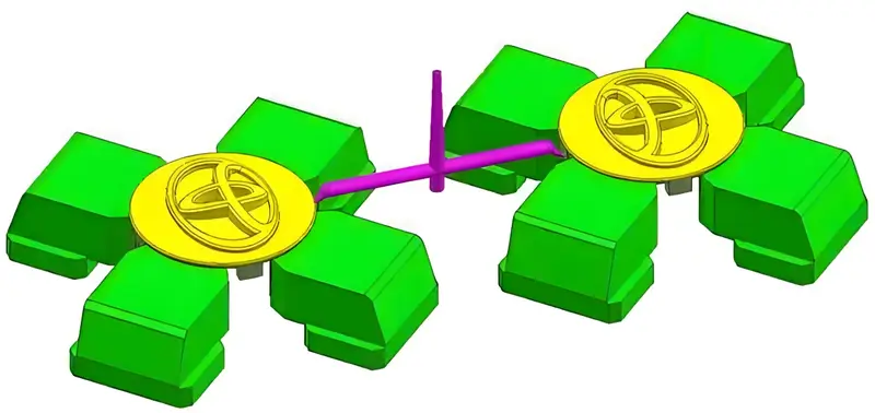
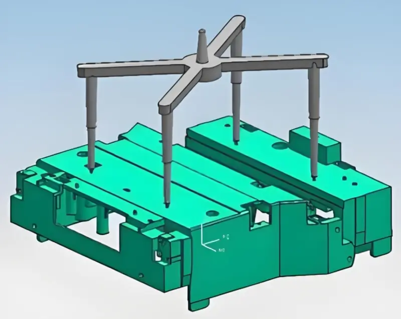
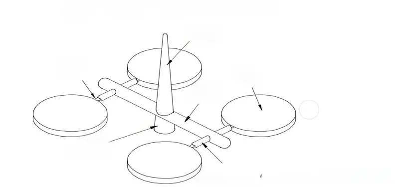
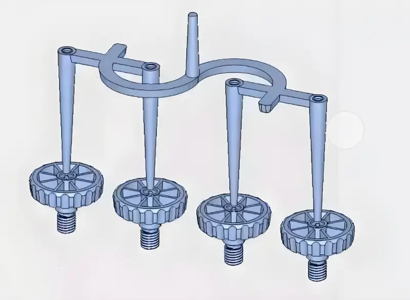
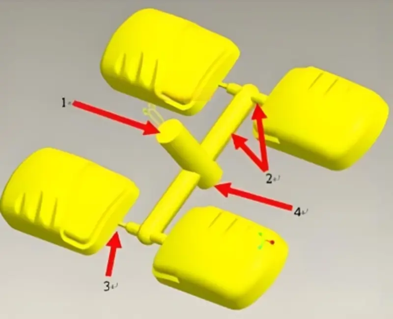
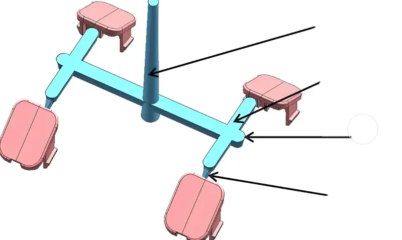
A koşucu sistemi1Yolluk sistemi veya dökme sistemi olarak da adlandırılan yolluk sistemi, bir enjeksiyon kalıplama makinesinin enjeksiyon memesinden kalıbın boşluğuna erimiş plastik için gerekli geçittir. Bir yolluk sistemi bir ana yolluk, bir manifold ve bir kapıdan oluşur.
Ana Koşucu
Ana yolluk, enjeksiyon yolluk veya dikey yolluk olarak da bilinen bu yolluk, ejektör nozülünün kalıbın ana yolluk burcu ile temas eden kısmından başlayıp manifoldda son bulan yolluktur. Bu kısım, erimiş plastiğin kalıba girdikten sonra içinden aktığı ilk kısımdır.
Ayrı Koşucu
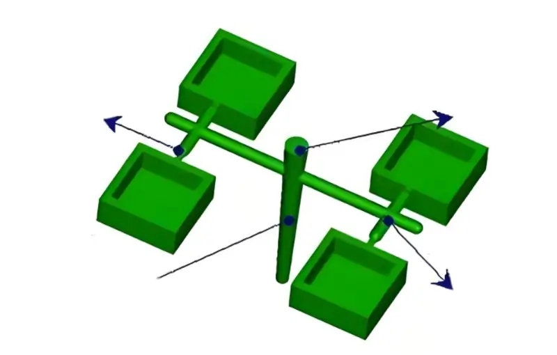
Bölünmüş yolluk veya ikincil yolluk olarak da bilinir. Kalıp tasarımına bağlı olarak, bir birinci yolluk ve bir ikinci yolluk olarak da ayrılabilir. Manifold, ana yolluk ile yolluk arasındaki geçiş alanıdır ve erimiş plastik akışının yumuşak bir şekilde geçişine izin verir; çok boşluklu kalıplar için plastiği çeşitli boşluklara eşit olarak dağıtma işlevi de görür.
Kapı
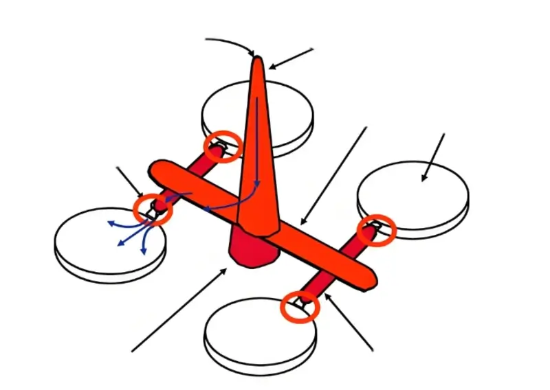
Yolluk olarak da bilinen bu parça, yolluk ile kalıp boşluğu arasındaki dar açıklıktır ve aynı zamanda en kısa ve en ince parçadır. İşlevi, akış yüzeyini sıkılaştırarak plastiği hızlandırmaktır. Yüksek kesme hızı plastiğin iyi akmasını sağlayabilir (plastiğin kesme inceltme özelliği nedeniyle); viskoz ısıtmanın ısınma etkisi de malzeme sıcaklığını yükseltme ve viskoziteyi düşürme etkisine sahiptir.
Kalıplamadan sonra, plastiğin geri akmasını ve kalıp boşluğundaki basıncın çok hızlı düşmesini önleyen ve kalıplanmış ürünün büzülmesine neden olan ilk sertleşen ve sızdırmaz hale gelen kapıdır. Kalıplamadan sonra, yolluk sistemini ve kalıplanmış parçayı ayırmak için kesmek kolaydır.
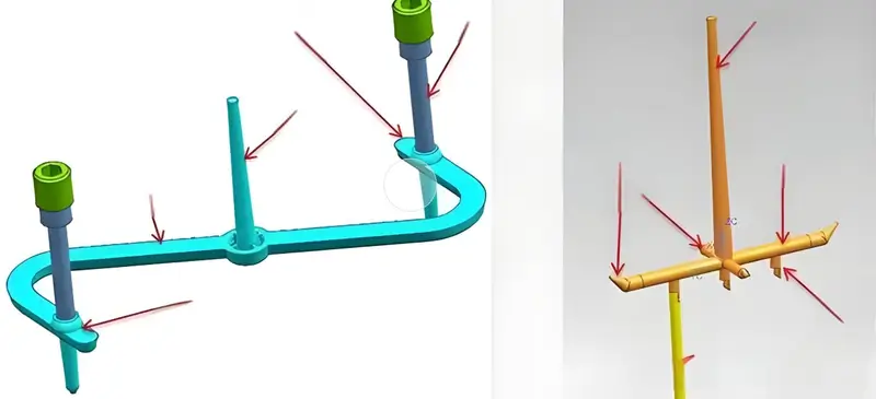
Soğuk Besleme Kuyuları
Soğuk sümüklü böcek kuyusu olarak da adlandırılır. Dolumun başlangıcında soğuk plastik dalga cephesini depolamak ve yenilemek için kullanılır, soğuk malzemenin doğrudan kalıp boşluğuna girmesini ve dolum kalitesini etkilemesini veya kapıyı tıkamasını önler. Soğuk slug kuyuları genellikle ana yollukların sonuna yerleştirilir, ancak yolluk uzun olduğunda, soğuk slug kuyuları da sona yerleştirilmelidir.
Yolluk sistemleri enjeksiyon kalıplamada erimiş plastik akışını düzenler.Doğru
Yolluk sistemleri plastiği verimli bir şekilde kalıba yönlendirerek düzgün dolum sağlar ve hataları azaltır.
Modern enjeksiyon kalıplamada yolluk sistemleri gereksizdir.Yanlış
Yolluk sistemleri, özellikle birden fazla boşluğa sahip kalıplarda erimiş plastik akışını yönlendirmek için gerekli olmaya devam etmektedir.
Yolluk Sistemi Tasarımının Temel Prensipleri Nelerdir?
Yolluk sistemi tasarımı, enjeksiyon kalıplamanın temel bir yönüdür ve üretim süreçlerinde verimliliği ve kaliteyi etkiler.
Yolluk sistemi tasarımı, düzgün malzeme dağıtımı için akış yollarını optimize eder, israfı en aza indirir ve döngü sürelerini azaltır. Önemli hususlar arasında kalıp performansını ve ürün bütünlüğünü geliştirmek için yolluk boyutu, açısı ve malzemesi yer alır..
Kapı Tasarımı Prensipleri
Seçin kapı konumu2 Parça üzerindeki tanık izlerini ve lekeleri en aza indirmek için parçanın kritik olmayan bir yüzeyinde veya özelliğinde. Enjeksiyon kalıplama sırasında plastik akışına yardımcı olmak ve kabarcıklar ve kısa çekimler gibi kusurları önlemek için geçit şeklini mümkün olduğunca basit tutun. Geçidi parçanın ihtiyaçlarına göre boyutlandırın.
Kapı çok büyükse, dökme süresi çok uzun olacaktır. Kapı çok küçükse, basınç çok yüksek olacaktır. Kapı ile ürün arasındaki bağlantı, çıkarma sırasında iz ve kaybı azaltmak için mümkün olduğunca pürüzsüz olmalıdır. Kapı sayısı mümkün olduğunca az olmalıdır. Birden fazla kapı enjeksiyon kalıplama3 dengesiz olması, tutarsız ürün boyutuna neden olur.
Kapıyı kalıplanan parçanın en kalın kısmına yerleştirin. Bu, eriyiğin önce kalın parçayı doldurmasını sağlar, bu da size daha iyi doldurma ve basınç tutma sağlar. Kapıyı tasarlarken, kalıbın içindeki havalandırmayı düşünün, böylece hava kabarcıkları veya rüzgar birikmesi olmaz. Kapıyı kalıplanan parçanın zayıf noktasına veya gömülü konumuna koymayın. Bu, gerilimleri yoğunlaştıracak ve kalıplanmış parçada kusurlara neden olacaktır.
Koşucu Tasarım İlkeleri
Düzensiz plastik akışının neden olduğu akış direncini ve kusurları en aza indirmek için yolluk şekli az sayıda dönüş veya keskin köşe ile basit olmalıdır. Yolluk uzunluğu, enjeksiyon döngüsünü ve plastiğin yoğuşma süresini azaltmak için mümkün olduğunca kısa olmalıdır.
Plastiğin yolluk içinde eşit şekilde akmasını sağlamak ve hava kabarcıklarını önlemek için yolluk kesit alanı kademeli olarak azaltılmalıdır. Yolluklar ve kalıp boşlukları arasındaki bağlantılar, ürün üzerindeki izleri ve kusurları azaltmak için plastik akarken çarpma ve ekstrüzyondan kaçınmak için mümkün olduğunca pürüzsüz olmalıdır.
- Boşluk düzenlemesi:Boşluğu düzenlerken dengeli bir düzen kullanmaya çalışın. Boşluğun düzeni, kalıbın dengesiz bir şekilde gerilmesini ve erimiş plastiğin taşmasını önleyebilecek kapı konumu ile simetrik olmalıdır. boşluk düzenlemesi4 mümkün olduğunca kompakt olmalı ve kalıbın boyutu küçültülmelidir, böylece erimiş plastik boşluğu doldurmak ve sorunsuz bir şekilde havalandırmak için yönlendirilebilir. Yolluk kesit alanının büyük olmasına, akışın kısa olmasına, ısı kaybının ve basınç düşüşünün mümkün olduğunca küçük olmasına dikkat edilmeli, yolluk işlemede yüzeyin pürüzlülüğünü sağlamalıdır. çok noktalı dökme, basınç düşüşünü ve gerekli enjeksiyon basıncını düşürmeye yardımcı olabilir, ancak aynı zamanda kaynak hatlarına da neden olabilir.
-
Koşucu dengesi5: Bir kalıpta birden fazla boşluğu doldururken, erimiş plastiğin her boşluğu mümkün olduğunca aynı anda doldurması için yollukları dengelemeyi düşünmeniz gerekir. Bu şekilde, her bir boşluktaki plastiğin tutarlı bir şekilde kalıplandığından emin olabilirsiniz. Manifoldları doğal olarak dengeli bir şekilde düzenleyerek yollukları dengeleyebilirsiniz. Doğal bir denge elde edemiyorsanız, yollukları dengelemek için yapay bir denge yöntemi kullanabilirsiniz.
-
Hurda: Plastik yollukların tasarımında akış ve basınç kaybı söz konusu değildir. Malzemeden tasarruf etmek, atıkları azaltmak ve geri dönüşüm maliyetlerinden tasarruf etmek için yolluk hacmini veya kesit alanını azaltabilirsiniz. Yolluk kesitinin boyutu, malzemenin akış özelliklerine uyacak şekilde aniden değil kademeli olarak değişmelidir. Üretkenliği artırmak ve kalıplama döngü sürelerini azaltmak, plastik işleyicilerinin ekonomik verimliliğini artırabilir.
-
Hava tahliyesi6:Plastiği boşluğu dolduracak şekilde yönlendirirseniz, boşluğun içindeki hava sorunsuz bir şekilde dışarı çıkabilir, böylece kapsülleme kavurma sorunu yaşamazsınız. Kısa atışlardan, çapaklardan, akış izlerinden ve artık gerilmeden kaçınmak istersiniz çünkü bunlar kalıplanmış ürünlerinizin kalitesini etkiler. Ayrıca plastik parçalarınızın görünümünü etkileyeceği için kavisli deformasyondan kaçınmak istersiniz.
Kalıp Boşluğu Düzenlemesinin Dikkate Alınması
Düzeni mümkün olduğunca dengeli hale getirmeye çalışın ve kalıp boşluğu7 Kalıp üzerindeki eşit olmayan stres ve eşit olmayan yüklemenin neden olduğu kalıp taşması sorununu önlemek için kapı açıklığı mümkün olduğunca simetrik olmalıdır; kalıbın boyutunu küçültmek için kalıp boşluğunun düzenini mümkün olduğunca kompakt hale getirmeye çalışın.
Akış Kılavuzunun Dikkate Alınması
Girdaplara neden olmadan kalıp boşluklarını doldurmak ve egzozu düzeltmek için erimiş plastiği nazikçe yönlendirin; Çekirdeğin hareket etmesini veya deforme olmasını önlemek için erimiş plastiğin daha küçük çaplı çekirdek ve metal uçları çok fazla itmesini önlemeye çalışın.
Isı Kaybı ve Basınç Düşüşünün Dikkate Alınması
Isı kaybı ve basınç düşüşü ne kadar az olursa o kadar iyidir. Akış kısa olmalıdır. Yolluk kesit alanı yeterince büyük olmalıdır.
Keskin kıvrımlardan ve akış yönünde ani değişikliklerden kaçının (kavisli bir açıyla yön değiştirin); yolluk yüzey pürüzlülüğü düşük olmalıdır; çok kapılı dökme basınç düşüşünü ve gerekli enjeksiyon basıncını azaltabilir, ancak kaynak hattında bir sorun olacaktır.
Akış Dengesinin Dikkate Alınması
Tek bir kalıpta birden fazla boşluğu doldurduğunuzda akış kanalı8. Her bir kalıp boşluğundaki kalıplanmış ürünlerin kalitesinin tutarlılığını sağlamak için plastiğin her bir kalıp boşluğunu aynı anda doldurmasını sağlamaya çalışın. Manifold için doğal dengeli düzenlemeyi benimsemeye çalışın. Doğal olarak dengelenemediğinde, akış kanalını dengelemek için yapay dengeleme yöntemini kullanın.
Atık Malzemenin Değerlendirilmesi
Dolgunun düzgün olduğundan ve herhangi bir akış veya basınç kaybına neden olmadığından emin olmak için, yolluk boyutunu (uzunluk veya kesit alanı) mümkün olduğunca azaltmalısınız. Bu, yolluk miktarını en aza indirmenize yardımcı olacaktır. koşucu atığı9 ve geri dönüşüm maliyeti.
Soğuk Malzeme Hususları
Uygun tasarım soğuk malzeme kuyuları10 ve yolluk sistemi üzerindeki taşma tankları, dolumun başlangıcında soğuk plastik dalga cephesini toplamak ve soğuk malzemenin doğrudan kalıp boşluğuna girmesini önlemek için dolum kalitesini etkileyecektir.
Hava Tahliyesinin Dikkate Alınması
Plastik, kalıp boşluğunu doldurmak için düzgün bir şekilde yönlendirilmeli ve kapsülleme kavurma sorununu önlemek için boşluk içindeki hava düzgün bir şekilde dışarı çıkabilmelidir.
Kalıplanmış Ürün Kalitesinin Dikkate Alınması
Kısa atışlar, parlama, batma izleri, kaynak çizgileri, akış izleri, jetler, artık gerilmeler, çarpılma, kalıp kayması vb. kullanmayın. Akış yolu sistemi uzun veya çok noktalı enjeksiyon olduğunda, akış dengesizliği, yetersiz basınç tutma veya düzensiz büzülme nedeniyle ürünün çarpılmasını ve deformasyonunu önlemek gerekir. Ürün iyi bir görünüme sahiptir, kapıyı çıkarmak ve düzeltmek kolaydır ve kapı işareti kalıplanmış parçanın görünümünü ve uygulamasını etkilemez.
Üretim Verimliliğinin Dikkate Alınması
Kalıplama döngüsünü kısaltmak ve üretkenliği artırmak için gereken son işlemleri en aza indirin.
Fırlatma Noktasının Dikkate Alınması
Kalıplanmış parçaların deforme olmasını önlemek için doğru ejektör konumunu seçtiğinizden emin olun.
Kullanılacak Plastiklerin Değerlendirilmesi
Yüksek viskoziteli veya kısa L/t'li plastikler için çok uzun veya çok küçük yolluklar kullanmayın.
Doğru yolluk sistemi tasarımı, malzeme akışını ve döngü süresini iyileştirir.Doğru
Optimize edilmiş yolluk sistemleri verimli malzeme dağıtımı sağlayarak döngü sürelerini azaltır ve genel üretim verimliliğini artırır.
Tüm yolluk sistemleri aynı malzemeleri kullanır.Yanlış
Yolluk sistemleri, özel kalıp gereksinimlerine uymak için termoplastikler ve metaller de dahil olmak üzere uygulama ihtiyaçlarına göre malzeme seçiminde farklılık gösterir.
Enjeksiyon Kalıbının Kapısı Nasıl Makul Tasarlanır?
Makul bir enjeksiyon kalıbı kapısı tasarlamak, çeşitli endüstrilerde başarılı üretim süreçleri için çok önemli olan ürün kalitesini ve üretim verimliliğini artırır.
Bir enjeksiyon kalıbı kapısı tasarlarken, kaynak çizgilerini en aza indirmek ve iyi bir yüzey kalitesi sağlamak için malzeme akışını, parça geometrisini ve kapı konumunu göz önünde bulundurun. Özel uygulama ihtiyaçlarına göre kenar, pim veya diyafram kapakları arasından seçim yapın.

Kapı Konumunun Seçimi
Geçidi parçanın en kalın kısmına yerleştirin. En kalın kısımdan yolluk açmak daha iyi dolum ve basınç tutma sağlar. İyi bir basınç tutma özelliğine sahip değilseniz, daha ince alanlar daha kalın alanlardan önce donacaktır. Geçidi kalınlıkta ani bir değişikliğe koymayın çünkü histerezis veya kısa atışlar elde edersiniz.
Mümkünse ürünün ortasından dökün. Kapıyı ürünün ortasına yerleştirmek size eşit akış uzunlukları sağlar, bu da ihtiyacınız olan atış basıncını etkiler ve merkez besleme, tutma basıncını her yönde eşit hale getirir ve eşit olmayan hacim büzülmesini önler.
Plastik yolluk içine akarken, plastik önce kalıp yüzeyinin yakınında soğutulur ve katılaştırılır. Plastik tekrar ileri doğru akarken, sadece katılaşmış plastik tabaka akar. Plastik zayıf bir ısı iletkeni olduğundan, katı plastik adyabatik bir tabaka oluşturur ve tabakanın akmasını sağlar.
Bu nedenle, ideal olarak, en iyi plastik akış etkisini elde etmek için geçit çapraz yolluk katmanına yerleştirilmelidir. Bu durum genellikle yuvarlak ve altıgen çapraz yolluklar için geçerlidir. Ancak trapez çapraz yolluklar bunu yapamaz çünkü geçit yollukların ortasında olamaz.
Seçin kapı konumu11 mümkün olduğunca ayırma yüzeyinde olmalıdır, böylece kalıp işleme ve kullanım sırasında kapı kolayca temizlenebilir; kapı ile boşluğun her bir parçası arasındaki mesafe mümkün olduğunca eşit ve mümkün olduğunca kısa olmalıdır; kapı konumu plastiğin boşluğa akmasını sağlamalıdır,
Kapı konumu, boşluk duvarı, maça veya kesici uç olduğunda plastiğin boşluğa akmayacağı şekilde olmalıdır, böylece plastik mümkün olan en kısa sürede boşluk parçalarına akabilir.
Ve çekirdeğin veya ek parçanın deformasyonunu önleyin; kapının konumu, ürünlerin füzyon izleri üretmesini veya füzyon izlerinin ürünün önemsiz kısımlarında üretilmesini önlemeye çalışmalıdır; kapının konumu, sistemin ağzının parçalarını çıkarmak için en kolay yere yerleştirilmeli ve aynı zamanda mümkün olduğunca ürünün görünümünü etkilememelidir; kapının konumu, serpantin akışı üretmek için doldurma işleminde enjeksiyonda kapı oluşturması önlenmelidir.
Kapı Kesitinin Boyutu
Genel olarak, kapı boyutu büyük değil küçük olmalıdır. İlk olarak, daha küçük bir boyut ayarlayın. Ardından, test kalıbındaki boşlukların dolum durumuna göre boyutu ayarlayın. Özellikle çok gözlü bir kalıp söz konusu olduğunda, ayarlanan kapak boyutu aynı zamanda boşluklara tutkal beslemesinin homojenliğini sağlayabilir. Aynı zamanda, küçük kapı eriyik hızını artırabilir. Eriyik sıcaklığının artırılması doldurma için iyidir ve küçük kapılar da çıkarma için iyidir.
Ancak çok kalın olan ürünler için, geçit çok küçükse, geçit erken sertleşecek ve yetersiz ikmal nedeniyle ürün kusurlarına neden olacaktır. Bu nedenle, kapının spesifik boyutu, kapının spesifik şekline göre belirlenmelidir.

Kapı Şekli
-
Doğrudan Geçitleme: Doğrudan yolluk en basit yolluk türüdür ve yolluk boyutu tasarımı dikey ana yolluk tasarımını ifade eder. Başlıca avantajları kolay dolum, düşük basınç kaybı ve hızlı dolum hızıdır. Dezavantajı, geçitte çok fazla stres oluşturmanın kolay olması, bu da ürünün deforme olmasını kolaylaştırması ve aynı zamanda geçidin boyutunun büyük olmasıdır. Çıkarma işlemi uygun değildir. Ürünün görünümünü etkiler. Doğrudan yolluk esas olarak büyük ve derin fıçı şeklindeki ürünler için kullanılır.
-
Yan kapı: Ortak kapı olarak da bilinen yan kapı, aşağıdaki ana özelliklere sahiptir: basit şekil, işlenmesi kolay, kapının onarımı kolay, çeşitli şekillerde ürünler için kullanılabilir, ancak PC malzemesi veya şeffaf parçalar kullanılmamalıdır ve diğer ince ve uzun namlu şeklindeki ürünler kullanılmamalıdır.
-
Yelpaze şeklinde kapı: Balık kuyruğu geçidi olarak da adlandırılan yelpaze geçidi, yolluktan boşluğa yelpaze şeklinde açılan bir geçit türüdür. Enjeksiyon sırasında parçanın iç gerilimini azaltabilir ve esas olarak düz parçalar ve sığ kabuk veya kutu şeklindeki parçalar için kullanılır.
-
İnce tabaka geçit: İnce sac geçit esas olarak büyük yassı ürünler için uygundur, bu da ürünleri deformasyona, akış izlerine, kabarcıklara vb. daha az eğilimli hale getirir. Dezavantajı, kapının kesilmesinin kolay olmamasıdır. Dezavantajı, kapının kesilmesinin kolay olmamasıdır.
Doğru kapı tasarımı enjeksiyon kalıplamada üretim hatalarını azaltır.Doğru
İyi tasarlanmış bir kapı, dengeli malzeme akışı sağlar ve kaynak hatlarını en aza indirerek nihai üründeki kusurları azaltır.
Tüm kapı tipleri herhangi bir enjeksiyon kalıplı ürün için uygundur.Yanlış
Kenar, pim ve diyafram gibi farklı geçit tipleri belirli uygulamalar ve malzemeler için uygundur, bu da geçit seçimini optimum sonuçlar için kritik hale getirir.
Enjeksiyon Kalıbının Yolluk Tasarımı Nasıl Hesaplanır?
Enjeksiyon kalıplarında yolluk tasarımının hesaplanması, dengeli ve verimli dolum sağlamak, üretimdeki hataları ve döngü sürelerini azaltmak için akış yollarının optimize edilmesini içerir.
Enjeksiyon kalıplamada yolluk tasarımı, eşit plastik akışı sağlayarak atık ve kusurları azaltır. Temel adımlar arasında parça geometrisine göre boyutlandırma, dengeli dolum için yerleşimi optimize etme ve malzeme özelliklerini dikkate alarak verimliliği ve kaliteyi artırma yer alır..
Boşluk Sayısı
Bir plastik kalıbın yolluklarını ayarladığımızda, boşluk sayısını dikkate almamız gerekir. Boşluk sayısı, hammaddelerin kalitesine, plastik parçaların geometrik yapı özelliklerine, boyutsal doğruluk gereksinimlerine, parti boyutuna, bakım ve onarım zorluğuna ve kalıp imalatının işlenebilirliğine vb. bağlıdır. Çeşitli faktörleri göz önünde bulundurarak boşluk sayısını hesaplıyoruz. Boşluk sayısını hesaplamak için formül aşağıdaki gibidir: Boşluk sayısı = L x k x tc/tm.
L parti başına ürün sayısı; tm gerekli birim üretim süresi; tc bir kalıp üretim döngüsü; K eleme faktörü.
- Enjeksiyon hacmi:Enjeksiyon kalıbı boşluğu, enjeksiyon makinesinin maksimum enjeksiyon hacmi ile doldurulabilir veya doldurulmayabilir. Kalıp boşluğunu tasarlarken, enjeksiyon makinesinin maksimum enjeksiyon hacmi aralığını göz önünde bulundurmanız gerekir. Enjeksiyon makinesinin maksimum enjeksiyon hacmi, plastik parçanın hacminden daha büyük olmalıdır. Enjeksiyon hacminin plastik parçanın gereksinimlerini karşılaması gerekir. Genel ortak enjeksiyon formülü şöyledir: NM1 + M2 =
M, enjeksiyon makinesinin maksimum enjeksiyon hacmidir. M1 büyük plastik parçanın kütlesi veya hacmidir. M2, ihtiyacınız olan dökme sisteminin plastik kütlesidir.
- Plastikleştirme kapasitesi:Boşluk sayısı enjeksiyon makinesinin plastikleştirme kapasitesine göre belirlenir. Enjeksiyon makinesinin plastikleştirme kapasitesine bağlı olarak boşluk sayısını hesaplamak için formül şöyledir: P/(X×W).
P enjeksiyon makinesinin plastikleştirme kapasitesi; X dakika başına enjeksiyon sayısı; W plastik parçanın ağırlığı.
Boşluk Düzenlemesi
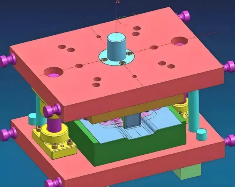
Kaç boşluğa ihtiyacınız olduğunu öğrendikten sonra, boşlukların düzenine bakmanız gerekir. Her bir boşluğun ana yollukla ilişkili olarak nerede olduğunu düşünmelisiniz. Ana yolluktan her bir boşluğa olan mesafenin kısa olduğundan emin olmalısınız, böylece çok fazla basınç düşüşü yaşamazsınız. Kalıplanan parçadaki iç gerilimin aynı olması için her bir boşluğa giren eriyiğin sıcaklığının aynı olduğundan emin olmalısınız.
Yapabiliyorsanız, delikler arasındaki mesafeyi mümkün olduğunca büyük yapın, böylece üst çubuğu su kanalına bağlamak kolay olur.
Çubuk ve soğutma su yolu. Reaksiyon kuvvetinin enjeksiyonundaki boşluklar, stres dengesini sağlamak için namlunun merkezine karşılık gelebilecek şekilde şablonun merkezinde hareket etmelidir. Kalıptaki boşlukların düzenlenmesi dengeye göre dengeli ve dengesiz olarak ikiye ayrılabilir, plastik kalıplardaki boşlukların seçiminde dengeli düzenlemeyi benimsemeye çalışın.
Yolluk Boyutunun Hesaplanması
Yolluk uzunluğu ve çapı erimiş malzemenin akış direncini etkileyecektir. Akış direnci ne kadar büyük olursa, boşluğu doldurmak için gereken basınç düşüşü de o kadar büyük olur. Yolluk çapının artırılması akış direncini azaltacaktır, ancak aynı zamanda hammadde miktarını artıracak ve soğutma hızını yavaşlatacaktır. Bu nedenle, yolluk boyutunu tasarlarken, yolluk çapını makul bir şekilde ayarlamak için kalıp akış analizini kullanmak gerekir. Yolluk çapı için ilk tahmini formül şöyledir:
D=W1/2×L1/4/3.7 D, yolluk çapıdır (mm); W, kalıplanan parçanın ağırlığıdır (g); L, yolluk uzunluğudur (mm).
Yolluk Kesitinin Seçimi
Enjeksiyon kalıplamada yaygın olarak kullanılan birkaç farklı tipte yolluk kesiti vardır. Bunlar arasında modifiye edilmiş trapez yolluk kesiti, dairesel yolluk, trapez yolluk kesiti, yarı dairesel yolluk kesiti ve dikdörtgen yolluk bulunmaktadır. Yolluk kesitini tasarlarken, yolluktaki basınç düşüşünü en aza indirmek önemlidir. Bu, yolluk kesitini mümkün olduğunca büyük yaparak elde edilebilir.
Isı kaybını azaltmak için yolluk kesit alanını azaltmanız gerekir. Yolluk verimliliği, yolluk kesit alanının yolluk kesitinin çevresine oranıdır. Dairesel bir yolluk en yüksek yolluk verimliliğine ve en düşük basınç düşüşü ve ısı kaybına sahiptir. Ancak, dairesel yollukların hareketli ve sabit kalıp plakalarını işlemeniz gerekir ki bu da pahalıdır. Bu nedenle, hareketli ve sabit kalıp yolluklarını hizalamanız ve kalıbı kapatırken işleme hassasiyetini artırmanız gerekir.
Doğru yolluk tasarımı, enjeksiyon kalıplamada malzeme israfını azaltır.Doğru
Akış yollarını optimize eden yolluk tasarımı, homojen dolum sağlar ve fazla malzeme kullanımını en aza indirerek daha az atık oluşmasını sağlar.
Tüm yolluk tasarımları aynı formül kullanılarak hesaplanabilir.Yanlış
Yolluk tasarım hesaplamaları belirli parça geometrisine, malzeme özelliklerine ve kalıplama gereksinimlerine bağlıdır ve her senaryo için özel yaklaşımlar gerektirir.
Sonuç
Bu makale esas olarak, yolluk ve geçitlerin tasarım ilkeleri ve prensipleri hakkındadır. enjeksi̇yon kaliplari12. Ana yolluk, manifold, kapı ve soğuk malzeme kuyusu dahil olmak üzere yolluk sisteminin bileşenlerini tanıtır ve kapı konumunu, şeklini, boyutunu ve yolluk tasarımını etkileyen faktörleri tartışır.
Bir kalıp tasarlarken pek çok şeyi düşünmeniz gerekir. Ürünün nasıl göründüğünü, nasıl dolduğunu, yollukların nasıl dengelendiğini, atıkları nasıl kontrol ettiğinizi ve basıncın nasıl düştüğünü düşünmeniz gerekir. Tüm bunlar kalıbın kalitesini ve ne kadar üretken olduğunuzu etkiler. Kalıbı doğru tasarlarsanız, iyi bir akış, daha az kusur ve daha iyi bir süreç elde edersiniz.
-
Yolluk sistemini anlamak, enjeksiyon kalıplama sürecini optimize etmek ve kaliteli üretim sağlamak için çok önemlidir. ↩
-
Doğru kapı konumunun seçilmesi kusurları en aza indirir ve ürün kalitesini artırır; optimum sonuçlar için en iyi uygulamaları keşfedin. ↩
-
Etkili enjeksiyon kalıplama tasarımına yönelik temel teknikleri ve ilkeleri anlamak, kalite ve verimliliği sağlamak için bu kaynağı keşfedin. ↩
-
Enjeksiyon kalıplama süreçlerinde kalıp performansını ve ürün tutarlılığını artırmak için etkili boşluk düzenleme stratejilerini keşfedin. ↩
-
Yolluk dengesini anlamak, kalıplanmış ürünlerde tutarlı kalite elde etmek için çok önemlidir. Önemi hakkında daha fazla bilgi edinmek için bu bağlantıyı keşfedin. ↩
-
Kalıplanmış ürünlerde kusurları önlemek için hava tahliyesi şarttır. Bu bilgilendirici kaynakta kalite ve verimliliği nasıl etkilediğini keşfedin. ↩
-
Kalıp boşluğu tasarımını anlamak, üretim verimliliğini ve ürün kalitesini optimize etmek için çok önemlidir. Uzman görüşleri için bu kaynağı keşfedin. ↩
-
Akış kanallarının dengelenmesi, tutarlı ürün kalitesi için çok önemlidir. Bu kaynak, dengenin sağlanmasına yönelik değerli teknikler ve ipuçları sunmaktadır. ↩
-
Bu kaynağın incelenmesi, runner atıklarının azaltılması, üretimde sürdürülebilirliğin ve maliyet verimliliğinin artırılması için etkili stratejiler hakkında fikir verecektir. ↩
-
Soğuk malzeme kuyularını anlamak, enjeksiyon kalıplamada daha iyi dolum kalitesi ve verimlilik için tasarımınızı geliştirebilir. ↩
-
Kapı konumu hakkında bilgi edinmek, kalıplanmış ürünlerinizin kalitesini ve verimliliğini önemli ölçüde etkileyebilir. ↩
-
Enjeksiyon Kalıpları hakkında bilgi edinin: Kapsamlı Bir Kılavuz: Enjeksiyon kalıpları, otomotiv bileşenleri, tüketici elektroniği ve ev eşyaları da dahil olmak üzere çok çeşitli ürünlerin oluşturulması için gereklidir. ↩


