 İçeriğe geç

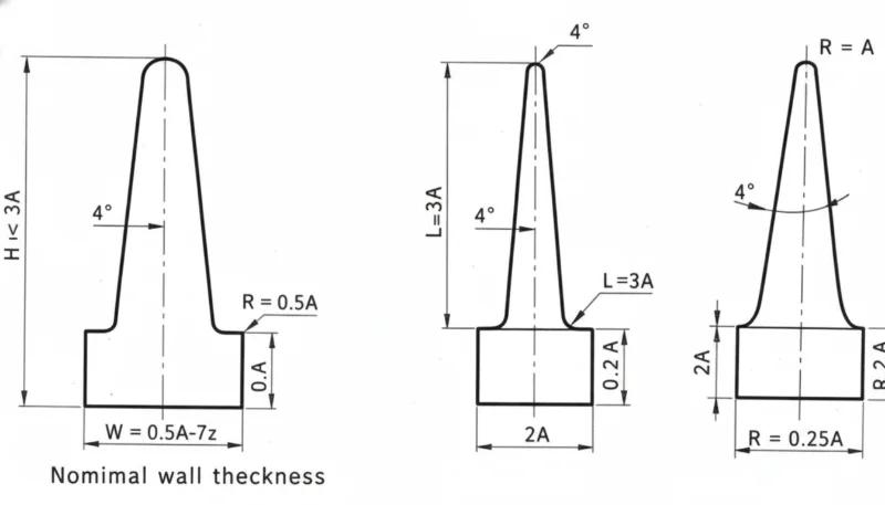
- Standart enjeksiyon kalıplama, genel boyutlar için ±0,1–0,3 mm toleranslar sağlar; premium kalıplama ve kontrollü işlemle ±0,05 mm'ye kadar dar toleranslı özellikler elde edilebilir. Ancak plastik parçalar, malzemeye ve geometriye bağlı olarak %0,4–2,0% oranında büzülme yaşar ve bu durum kalıp tasarımında telafi edilmelidir. Kaynak çizgileri—iki akış cephesinin buluştuğu noktalar—görünür yüzey izleri oluşturur ve yerel mukavemeti –30% oranında azaltır.
- Design constraints include uniform wall thickness, adequate draft angles, and avoidance of sharp undercuts.
- Material selection is limited to compatible thermoplastics and thermosets; not all polymers process well.
- Cycle time depends on part geometry and cooling efficiency, affecting per-unit economics at low volumes.
- Understanding process limitations early prevents costly mold revisions and production delays.
What Are the Main Limitations of Injection Molding?
Injection molding imposes five core limitations: high upfront tooling cost3 ($5,000–$100,000+), geometry constraints (uniform wall thickness4, mandatory draft angle1, no sharp undercuts), a restricted material library, long lead times of 4–12 weeks for mold fabrication, and difficulty economically producing low-volume runs below 1,000 parts.
In our factory, we evaluate every new project against these constraints before committing to tooling. A part with 0° draft angle or 8 mm walls on one side and 2 mm on the other will cause ejection failures and sink marks2 respectively—both costly to fix after the mold is cut.
Why Is Tooling Cost a Fundamental Limitation?
Mold fabrication is capital-intensive. A simple single-cavity aluminum mold starts at $5,000; a complex multi-cavity P20 or H13 steel mold for high-volume production routinely exceeds $80,000. This upfront tooling cost makes injection molding economically unviable for quantities below roughly 1,000–5,000 parts, where per-unit cost from CNC machining or 3D printing remains competitive.
Tooling cost also escalates with part complexity. Side actions for undercuts add $2,000–$15,000 per action. Lifters, collapsible cores, and hot-runner systems each multiply the base mold cost. Engineers must weigh these costs against projected production volumes during design for manufacturability review.
Beyond initial mold fabrication, ongoing maintenance adds to the total cost of tooling. Every 100,000–500,000 shots, mold components require inspection and replacement. Ejector pins, slides, and gate inserts wear first. Cavity surfaces develop micro-cracks from thermal cycling that require polishing or re-hardening. Over the life of a mold producing 2–5 million parts, maintenance costs may equal 20–40% of the original mold price, a hidden expense that must be factored into total cost of ownership analysis.
Multi-cavity molds amplify both the cost and the risk. A 16-cavity mold that produces 16 parts per cycle costs significantly more than a 1-cavity mold, but any defect in a single cavity—a scratch, a worn ejector, a flow imbalance—affects the entire production run. Balancing runners, matching cavity temperatures, and maintaining dimensional consistency across all 16 cavities requires precision and vigilance. When one cavity drifts out of tolerance, the entire mold must be pulled for inspection.
“High tooling cost is the primary barrier to injection molding at low production volumes.”Doğru
Mold fabrication costs $5,000–$100,000+ before a single part is produced. At volumes below 1,000 units, this fixed cost per part is prohibitively high compared to subtractive or additive alternatives.
“Injection molds can be modified cheaply after the design is finalized.”Yanlış
Mold modifications—especially adding material to cavities or repositioning gates—typically cost $500–$10,000 per change and may require weeks of rework. Design reviews and DFM sign-off before mold cut prevent these expenses.
What Geometry Constraints Limit Part Design?
Injection molding enforces strict geometry rules. Draft angle of at least 1°–3° per side is mandatory on all vertical walls to enable part ejection. Wall thickness must remain uniform—typically 1.5–4.5 mm—because thick sections create sink marks and internal voids while thin sections cause short shots. Sharp internal corners cause stress concentrations; a minimum radius of 0.5× wall thickness is required.
Undercuts—features that prevent straight-pull mold opening—require side actions or collapsible cores, significantly increasing tooling cost and complexity. Complex geometries that are trivial in CNC machining (deep blind bores, re-entrant angles) become expensive or impossible in injection molding without creative mold design.
Wall thickness uniformity is among the most frequently violated design rules. In our factory, we see parts submitted with 2:1 to 5:1 thickness ratios. We require a maximum ratio of 3:1 between adjacent walls to avoid warping and sink marks. Our kalıp akış analizi service identifies these violations before tooling begins.
How Do Material Limitations Affect Injection Molding?
Not every polymer is injection moldable. High-melt-viscosity materials, highly filled composites (>50% glass or mineral), and thermosets with extremely short pot lives may be incompatible with standard injection molding equipment. Additionally, each resin has a narrow processing window: melt temperature, injection pressure, and cooling rate must all be within ±5–15% of optimal to produce acceptable parts.
Material selection also affects mold design. Abrasive glass-filled resins (e.g., 50% GF nylon) require hardened H13 or S7 steel instead of P20, raising tooling cost by 30–60%. Highly reactive thermosets require heated tooling and specialized venting. These material constraints limit design freedom and add complexity when switching resins mid-program.
Shrinkage is another material-driven limitation. Different resins shrink at different rates—semi-crystalline materials like nylon and polypropylene shrink 1.5–2.5%, while amorphous polymers like ABS and polycarbonate shrink only 0.4–0.8%. The mold must be machined oversized to compensate, but shrinkage varies with wall thickness, cooling rate, and packing pressure. When multiple resins are evaluated for a part, the mold may need adjustments for each, adding cost and time.
Coloring is also constrained. While masterbatches and pre-colored pellets offer broad color options, achieving consistent color match across production runs and across multiple machines is challenging. Metalized finishes, translucency, and optical clarity each require specific resin grades and surface finishes that limit material choices further.
“Material selection directly influences mold material requirements and tooling cost.”Doğru
Abrasive or corrosive resins require hardened or stainless steel tooling rather than standard P20. This upgrade adds 30–60% to base tooling cost and may extend lead time by 2–4 weeks.
“Any thermoplastic material can be processed on any standard injection molding machine.”Yanlış
Processing windows vary widely. PEEK requires barrel temperatures of 370–400°C and specialized screw designs, while standard PP runs at 200–240°C. Using incompatible equipment causes degradation, poor fill, and part failure.
What Are the Production Volume and Lead Time Limitations?
Injection molding is economically optimized for volumes above 10,000 parts per year. Below this threshold, the amortized tooling cost per part makes injection molding more expensive than CNC machining or hızlı prototipleme. The crossover point varies by part complexity, but typically occurs at 500–5,000 parts depending on mold cost.
Lead time is another structural limitation. From design freeze to first production parts, expect 4–12 weeks: 1–2 weeks for mold design, 3–6 weeks for mold machining and surface treatment, and 1–2 weeks for T1 sampling and validation. This timeline is largely fixed regardless of urgency, constraining injection molding for rapid iteration cycles.
In our factory, we run 47 injection molding machines and manage mold lead times aggressively. Even so, rush molds (2–3 week turnaround) require aluminum tooling or simplified single-cavity designs that may not match long-term production requirements. Low-volume injection molding with aluminum tooling is one strategy to bridge the gap, but it trades tool life (10,000–50,000 shots) for speed.
Scheduling constraints compound lead time limitations. High-demand mold shops book tooling slots 4–8 weeks in advance. Complex molds with multiple side actions, hot runners, or exotic steel require longer machining queues. Even when mold machining is complete, T1 sampling trials reveal dimensional deviations, surface defects, and fill problems that require additional mold modifications before parts meet specification. This iterative T1-T2-T3 validation cycle adds 2–6 weeks to practical lead times.
Supply chain disruptions affect mold steel availability as well. H13 and P20 tool steel, the most common mold materials, can have lead times of 4–8 weeks when demand is high. Mold base components—plates, leader pins, ejector systems—may also face delivery delays. Engineers planning injection molded product launches must build these material lead times into their project schedules to avoid surprises.
What Are the Surface Quality and Tolerance Limitations?
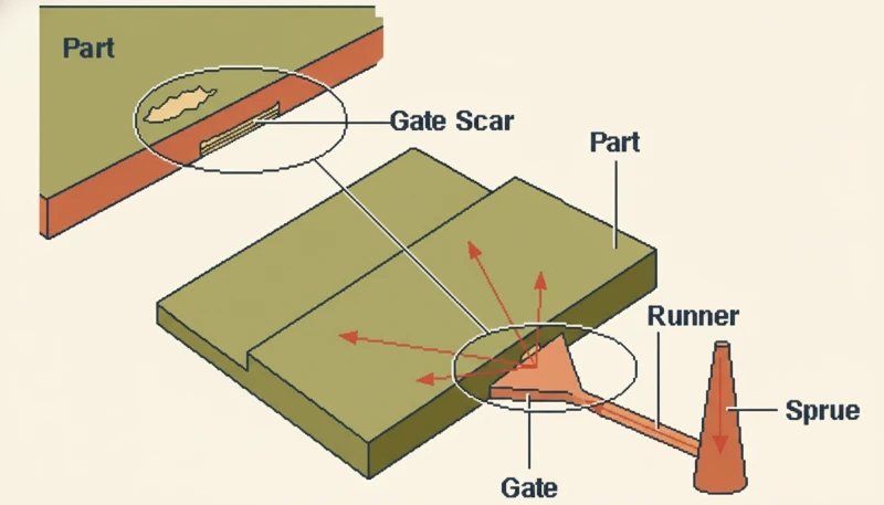
Standard injection molding achieves tolerances of ±0.1–0.3 mm for general dimensions, with tight-tolerance features achievable at ±0.05 mm with premium tooling and controlled processing. However, plastic parts experience shrinkage of 0.4–2.0% depending on material and geometry, which must be compensated in mold design. Weld lines—where two flow fronts meet—create visible surface marks and reduce local strength by 10–30%.
7 Önemli Enjeksiyon Kalıplama Kısıtlaması (Ve Bunların Üstesinden Nasıl Gelinir)
How Can Engineers Mitigate Injection Molding Limitations?
Effective mitigation begins at the design stage. Adhering to draft angle guidelines of 1°–3° minimum, maintaining uniform wall thickness within 25% of the nominal value, and avoiding undercuts wherever possible reduces tooling complexity and cost. Running kalıp akış analizi before mold cut identifies fill, cooling, and warpage issues before they are machined into steel.
For low-volume production, bridging strategies include 3D-printed tooling inserts (for < 100 parts), aluminum prototype molds ($2,000–$8,000, 10,000-shot life), and family molds that share a base with interchangeable inserts. These approaches reduce upfront investment while maintaining injection-molded surface quality and material performance.
In our factory, early DFM collaboration with customers saves an average of $8,000–$20,000 per project by catching wall thickness issues, undercuts, and draft problems before tooling begins. We treat every design review as an investment in avoiding the most expensive limitation of injection molding: mold rework after the first tool trial.
Simulation tools play a critical role in overcoming injection molding limitations. Mold flow analysis software predicts fill behavior, weld line locations, air trap positions, and cooling uniformity before the mold is cut. By resolving issues in simulation rather than in steel, engineers eliminate the majority of T1 failures. Our experience shows that comprehensive mold flow analysis reduces T1 revision cycles from an average of 3 to fewer than 1.5, saving 2–4 weeks of development time per project.
Process monitoring and statistical process control (SPC) further mitigate limitations in production. Real-time monitoring of injection pressure, cavity pressure, and melt temperature enables early detection of drift before parts go out of tolerance. Automated inspection with coordinate measuring machines (CMM) and optical comparators ensures that tolerance limitations are managed proactively rather than discovered at final inspection.
Sıkça Sorulan Sorular
Sıkça Sorulan Sorular
Enjeksiyon kalıplama için minimum duvar kalınlığı nedir?
The minimum wall thickness for injection molding is typically 0.8–1.0 mm for most thermoplastics, but practical production minimums are 1.5–2.0 mm to ensure adequate fill without excessive injection pressure. Thin walls below 1.0 mm require high injection pressures (1,200+ bar), specialized gating, and fast cycle times to prevent premature freeze-off. Material plays a key role: low-viscosity resins like nylon can fill thinner sections than high-viscosity materials like rigid PVC. Always consult material datasheets and confirm with a mold flow simulation before committing to wall thicknesses under 2.0 mm.
Enjeksiyon kalıplama neden pah açıları gerektirir?
Draft angle is required in injection molding because the molded part must release cleanly from the mold cavity as it opens. Without draft, the vertical walls grip the mold steel through friction and vacuum, causing part distortion, ejector pin damage, or mold damage during ejection. A minimum of 1° draft per side is standard for smooth surfaces; textured surfaces require 3°–5° per side to avoid drag marks. Parts with 0° draft can sometimes be ejected with forced air or specialized coatings, but this approach increases cycle time and reduces tool life. Incorporating draft from the earliest CAD stage avoids expensive mold modifications later.
Parça karmaşıklığı enjeksiyon kalıplama maliyetini nasıl etkiler?
Part complexity is the primary driver of tooling cost beyond part size. Each undercut requiring a side action adds $2,000–$15,000. Hot-runner systems for complex multi-gate parts add $5,000–$30,000. Parts with extremely tight tolerances (±0.02 mm) require precision grinding of mold inserts and extended validation. Surface texture, logos, and fine details require EDM (electrical discharge machining) of the mold cavity at additional cost. A simple box-shaped part with 2° draft and uniform 2.5 mm walls may cost $8,000 to tool; the same envelope with side-action undercuts, a textured exterior, and ±0.05 mm tolerances may exceed $40,000.
Enjeksiyon kalıplama sınırlamaları çok kısıtlayıcı olduğunda alternatifler nelerdir?
When injection molding limitations—high tooling cost, geometry constraints, or long lead time—are prohibitive, several alternatives exist. CNC machining is ideal for complex geometries, low volumes (1–1,000 parts), and metals. 3D printing (FDM, SLA, SLS) suits functional prototypes, patient-specific medical parts, and volumes under 200 units. Urethane casting uses silicone molds to replicate injection-molded surface quality at 10–150 parts per mold. Blow molding suits hollow parts like bottles. Thermoforming works for large, thin-wall panels. The best alternative depends on volume, material requirements, tolerance, and timeline. Many products begin with 3D printing or CNC machining before transitioning to injection molding at production scale.
Enjeksiyon kalıplama metal parçaları işleyebilir mi?
Standard injection molding processes only thermoplastics and thermosets, not bulk metals. However, metal injection molding (MIM) is a variant that processes metal powder mixed with a polymer binder, which is then debindered and sintered to produce near-net-shape metal parts. MIM is suitable for complex small metal parts (typically under 100 grams) with fine features that are difficult to machine. The process requires dedicated equipment and sintering furnaces, and tooling costs are comparable to plastic injection molds. MIM competes with investment casting and CNC machining for complex, high-volume small metal components in aerospace, medical, and firearms industries.
Enjeksiyon kalıplamada duvar kalınlığı düzensiz olduğunda ne olur?
Non-uniform wall thickness in injection molding causes several defects. Thick sections take longer to cool, causing the outer skin to solidify while the core is still molten; as the core contracts, it pulls the surface inward, creating sink marks. Differential cooling rates between thick and thin sections generate internal stresses that manifest as warping after ejection. In severe cases (ratio > 4:1), thick sections develop voids as the material pulls away from the solidifying skin. Corrective options include coring out thick sections (adding material in the mold to create a hollow structure), adding ribbing instead of thick walls, and using mold flow analysis to predict and mitigate these effects before cutting the tool.
-
draft angle: Draft angle is a slight taper applied to vertical walls of a molded part, measured in degrees, to allow the part to release cleanly from the mold. ↩
-
sink marks: Sink marks refers to surface depressions that form on injection-molded parts when the outer skin solidifies before the inner core, causing inward shrinkage. ↩
-
tooling cost: Tooling cost is a capital expenditure measured in US dollars that covers mold design, machining, and validation before the first production part is made. ↩
-
wall thickness: Wall thickness refers to the measured distance between the inner and outer surfaces of a molded part, typically ranging from 1.5 mm to 4.5 mm for thermoplastics. ↩


