 Перейти к содержанию

Если вы sourcing литьевых деталей и оценки вариантов пресс-форм, система холодной обкатки1 — это одно из первых решений, с которым вы столкнётесь. Это более простая, дешёвая и широко используемая конфигурация литниковой системы — но это не значит, что она всегда является правильным выбором. Понимание того, когда холодноканальная система оправдана, как её правильно спроектировать и какие материалы по ней лучше всего протекают, может сэкономить вам тысячи долларов на пресс-форму и недели времени на отладку. В этом руководстве мы разбираем всё, что инженеру или менеджеру по закупкам необходимо знать о холодноканальных системах — от базовой механики до практических советов по проектированию, основанных на двадцатилетнем опыте изготовления пресс-форм.
- Холодноканальные системы — это неизолированные каналы, по которым расплавленный пластик подаётся в полости пресс-формы.
- Основными конфигурациями холодной разводки являются двухплитные и трёхплитные формы.
- Холодные литники идеально подходят для коротких серий, крупных изделий и термически чувствительных материалов.
- Объём отходов литника в 15–30% типичен, но перерабатываем с термопластами.
- Балансировка конструкции и размещение литников — две наиболее важные переменные.
Что такое система с холодной разводкой в литье под давлением?
Система с холодной разводкой в литье под давлением определяется функцией, ограничениями и компромиссами, описанными в этом разделе. Система с холодной разводкой — это сеть необогреваемых каналов внутри литьевой формы, доставляющая расплавленный пластик от сопла машины к затворам полостей и затвердевающая с каждым циклом.
На практике холодный литник является стандартной конфигурацией для большинства литьевых пресс-форм в мире. Он механически прост, не требует контроллеров температуры или нагреваемых компонентов и надёжно работает с широким спектром термопластов. Компромиссом является отход материала: затвердевший литник необходимо отделить от изделия и либо утилизировать, либо перемолоть и переработать. Для массовых товарных изделий, где стоимость смолы невысока, такие отходы часто экономически приемлемы. Для инженерных смол или медицинских применений, где дроблёнка2 ограничена, экономика смещается в сторону горячеканальных систем.
Как работает система с холодной разводкой?
Принцип работы прост. На этапе впрыска винт машины проталкивает расплавленный пластик через сопло в литниковую втулку формы. Из литника расплав течёт по основному каналу разводящей системы, который разветвляется на вторичные каналы, каждый из которых заканчивается у литника (затвора), ведущего в полость формы. Поскольку форма поддерживается при температуре значительно ниже температуры плавления полимера (обычно 20–80 °C в зависимости от материала), пластик в разводящей системе начинает охлаждаться в момент контакта со стальными стенками.
После того как деталь уплотнена и достаточно охлаждена, пресс-форма открывается, и система выталкивания выталкивает как готовую деталь, так и затвердевшую литниковую систему из формы. В двухплитной пресс-форме литниковая система выталкивается с той же стороны, что и деталь. В трёхплитной пресс-форме литниковая система снимается отдельно, что позволяет автоматически отделять её без ручного вмешательства. Затем цикл повторяется.
Ключевые переменные, влияющие на работу холодноканальной системы, включают: диаметр литника (обычно 3–12 мм в зависимости от размера детали и вязкости материала), длину литника (чем короче, тем лучше для падения давления), тип и размер точки впрыска (краевые, подводные и игольчатые точки впрыска являются наиболее распространёнными), и количество гнёзд в компоновке. Хорошо спроектированная холодноканальная система обеспечивает равномерное заполнение каждого гнезда с минимальными потерями давления и приемлемым объёмом отходов.
Какие бывают типы холодноканальных пресс-форм?
Существует две основные конфигурации холодноканальных систем: двухплитные и трёхплитные пресс-формы. Третий вариант — изолированная литниковая система — существует, но редко встречается в современном производстве.
Двухплитная холодноканальная пресс-форма
Двухплитная пресс-форма — это самая простая и экономичная конфигурация. У неё одна линия разъёма: форма разделяется на две половины — сторону полости (сторона A) и сторону сердечника (сторона B). Литниковая система фрезеруется в одной или обеих половинах по линии разъёма. Когда форма открывается, и деталь, и затвердевшая литниковая система выпадают с одной стороны. Эта конструкция идеальна для деталей с точками впрыска на одной стороне и хорошо подходит для производства малых и средних объёмов, где допустима ручная обрезка литников или где роботизированные съёмники могут автоматически отделить литниковую систему.
Трёхплитная пресс-форма с холодным литником
Трёхплитная форма добавляет вторую плоскость разъёма, создавая три плиты: съёмную плиту, плиту А и плиту В. Разводящая система расположена на первой плоскости разъёма (между съёмной плитой и плитой А), в то время как изделие формируется на второй плоскости разъёма (между плитой А и плитой В). При выталкивании форма открывается на обеих плоскостях разъёма последовательно, автоматически отделяя разводящую систему от изделий. Это позволяет размещать литники на любой поверхности изделия (а не только на краю) и обеспечивает автоматическое отделение литников — значительное преимущество в условиях крупносерийного или автоматизированного производства.
Компромисс — это сложность: трёхплитные пресс-формы дороже в изготовлении и обслуживании, имеют большую высоту (требуют более крупных прессов) и добавляют подвижные компоненты, которые увеличивают износ. По нашему опыту, трёхплитные пресс-формы оправданы, когда геометрия детали требует центрального впрыска, когда объёмы производства превышают 100 000 циклов или когда затраты на ручную обрезку литников становятся непомерно высокими.
“Cold runner molds are the most widely used mold configuration worldwide for injection molding.”Правда
Это верно. Холодноканальные пресс-формы составляют большинство используемых в мире литьевых форм. Их простота, более низкая стоимость оснастки и широкая совместимость с материалами делают их выбором по умолчанию для большинства применений.
“In a three-plate mold, the runner and part eject from the same parting line simultaneously.”Ложь
В трёхплитной пресс-форме литник отделяется на отдельной плоскости разъёма от изделия, что обеспечивает автоматическое разделение. Это ключевое преимущество перед двухплитными пресс-формами, где и литник, и изделие выпадают из одной плоскости разъёма.
Когда стоит выбрать холодный литник вместо горячего?
Это самый частый вопрос от клиентов, оценивающих варианты пресс-форм. Ответ зависит от четырёх факторов: объёма производства, стоимости материала, геометрии детали и частоты смены цвета.
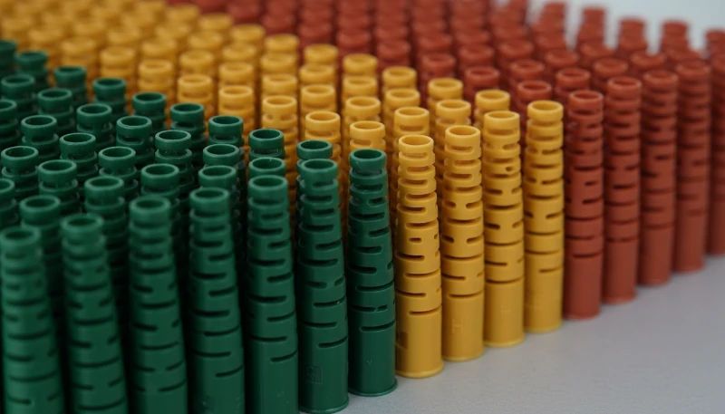
Холодноканальные системы являются лучшим выбором, когда: (1) Объём производства низкий или средний (менее 500 000 деталей) — чем ниже литьевая форма стоимость формы с холодной разводкой обеспечивает более быструю окупаемость. (2) Стоимость материала низкая — если вы отливаете PP, PE или PS стоимостью в несколько долларов за килограмм, потери на отходах разводки минимальны. (3) Частые смены цвета — холодная разводка очищается мгновенно, так как нет нагреваемых коллекторов для промывки. (4) Требуется многогнёздное производство с простой геометрией изделий.
Горячеканальные системы становятся более привлекательными при больших объёмах (свыше 1 миллиона деталей), с дорогими инженерными смолами, где устранение отходов литниковой системы позволяет значительно сэкономить на материале, или когда критически важна оптимизация времени цикла — горячеканальные системы могут сократить время цикла, исключая время, необходимое для охлаждения и выброса литниковой системы.
| Фактор | Cold Runner | Горячий бегун |
|---|---|---|
| Tooling cost | $5,000–$15,000 ниже | $15,000–$50,000 выше |
| Отходы разводки | 15–30 г отходов на цикл | Near zero |
| Color change | Быстро (3–5 циклов) | Медленно (10–30 циклов) |
| Техническое обслуживание | Низкий | Выше (нагреватели, термопары) |
| Время цикла | Дольше (охлаждение разводки) | Короче |
| Best for | Малый-средний объём, частые смены цвета | Большие объёмы, дорогие смолы |
Какие материалы лучше всего подходят для систем с холодной разводкой?
Большинство термопластов хорошо работают с холодной разводкой, но некоторые материалы подходят для этого лучше других. Ключевыми свойствами материала, влияющими на работу холодной разводки, являются вязкость расплава, термическая стабильность и поведение при усадке.
Полипропилен (ПП) и полиэтилен (ПЭ) являются наиболее распространёнными материалами для холодных литников по объёму. Их низкая стоимость, низкая вязкость и широкий технологический интервал делают их идеально подходящими для систем с ненагреваемыми каналами. Холодные литники из ПП встречаются повсеместно — от крышек для упаковки до корпусов автомобильных аккумуляторов.
Nylon (PA6, PA66) performs well in cold runners but requires careful attention to moisture content. Nylon is hygroscopic — it absorbs moisture from the air — and must be thoroughly dried before molding to prevent splay and weak weld lines. In a cold runner, the longer flow path compared to hot runners means the material must maintain sufficient temperature to avoid premature freeze-off. For glass-filled nylons (PA6-GF30, PA66-GF30), runner diameters should be increased by 20-30% to accommodate the higher viscosity.
Engineering Resins and Specialty Materials
Polycarbonate (PC) and acrylic (PMMA) are also well-suited to cold runners. These materials have higher melt temperatures (280-320 °C for PC) but good thermal stability, which means they flow well through unheated channels without premature solidification. PC in particular benefits from cold runner simplicity in optical lens and electronic housing applications, where material purity and surface finish consistency are essential. Acrylic (PMMA) cold runner molds are common in automotive lighting and display applications.
Materials that are challenging in cold runners include PVC (thermal degradation risk if the runner is too long), PEEK (very high melt temperature makes cold runners impractical for most applications), and liquid silicone rubber (LSR), which always requires a cold runner but of a completely different design. If you are working with specialty resins, talk to your литьё под давлением partner early in the design process to evaluate runner system feasibility and cost impact.
How Do You Design an Optimal Cold Runner System?
Good cold runner design is not complicated, but it demands attention to a few critical parameters. Get any of these wrong, and you will spend weeks debugging short shots, sink marks, or unbalanced fills.
Runner Diameter and Shape
The standard recommendation is a full-round runner cross-section, which provides the best surface-area-to-volume ratio for heat retention and low pressure drop. The runner diameter should be approximately 1.5× the maximum wall thickness of the part, with a practical range of 3–12 mm. Too small, and you get excessive pressure drop and premature freeze-off. Too large, and you waste material and extend cycle time. A trapezoidal runner is an acceptable alternative when both halves of the mold cannot be machined, but it increases pressure drop by 15–25% compared to a full-round design.
Runner Layout and Balancing
For multi-cavity molds, the runner layout must be balanced so that every cavity fills at the same time and pressure. An artificially balanced layout uses different runner diameters and lengths to equalize flow resistance. A naturally balanced layout arranges cavities symmetrically so that the flow path to each cavity is identical — these are always preferred because they are more robust to viscosity changes and process variations. In our mold shop, we use Moldflow simulation3 to verify fill balance before cutting steel, reducing first-shot debugging time by approximately 40%. With in-house mold manufacturing producing over 100 sets per month, we handle complex runner balancing across diverse part geometries.
Дизайн ворот
The gate is the narrowest point in the flow path and has the greatest impact on part appearance and dimensional accuracy. Common gate types for cold runners include: edge gates (simplest, used on the parting line), submarine gates (tunnel gates that are automatically sheared during ejection), and pin gates (small-diameter gates fed through a three-plate mold). Gate size should be approximately 50–80% of the part wall thickness at the gate location. Too small a gate causes high shear, which can degrade the material and create visible gate marks. Too large a gate extends packing time and makes degating difficult.
What Are Common Cold Runner Defects and How to Fix Them?
Common cold runner defects and how to fix them are the main categories or options explained in this section. Even with good design, cold runner molds can produce defects. Here are the most common issues we encounter and their solutions.
Short shots occur when the cavity does not fill completely. In cold runner molds, the most common cause is a runner that is too small or too long, creating excessive pressure drop. The fix is to increase runner diameter or reduce runner length by repositioning the cavities closer to the sprue. Increasing injection pressure or speed can also help, but this is a band-aid — the underlying geometry should be corrected.
Flow lines and weld lines appear where multiple flow fronts meet. In cold runner molds, these often occur at runner junctions or where two gates feed the same cavity. Solutions include: relocating gates to move weld lines to non-critical areas, increasing melt temperature to improve flow fusion, or using a single gate design for cosmetically critical parts.
“Regrind from cold runner waste can be blended with virgin material at 15–20% ratios for most non-critical thermoplastic applications.”Правда
Yes, this is standard industry practice. For commodity thermoplastics like PP and PE, regrind at 15–20% blend ratios maintains mechanical properties while significantly reducing effective material waste cost.
“Hot runner systems always produce higher quality parts than cold runner systems regardless of production volume.”Ложь
Quality depends on proper mold design, not runner type. Cold runners produce equally high-quality parts when well-designed. The choice depends on volume, material cost, and color change needs.
Excessive runner waste is not a defect per se, but it is a common cost concern. If runner waste exceeds 30% of the total shot weight, consider: reducing runner diameter (within pressure constraints), switching to a hot runner for the primary manifold while keeping cold runners for the final drops (a hybrid system), or implementing a regrind program to recycle the runner material. For most thermoplastics, regrind at 15–20% blend ratios is acceptable for non-critical applications.
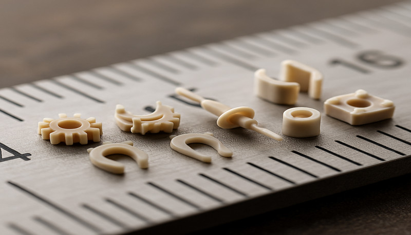
At ZetarMold, we have been building injection molds since 2005 — over 20 years of experience with both cold runner and hot runner systems. Our Shanghai facility operates 47 injection molding machines ranging from 90T to 1850T, giving us the flexibility to run cold runner molds for everything from small precision parts to large structural components. With our in-house mold manufacturing capability and experience across 400+ materials, we can help you determine the optimal runner system for your specific application.
What Are the Most Frequently Asked Questions About Cold Runner Systems?
What is the typical runner waste percentage in a cold runner mold?
Runner waste in a cold runner mold typically ranges from 15% to 30% of the total shot weight, depending on the number of cavities, runner layout, and part size. For small, multi-cavity molds, the runner volume can actually exceed the part volume, pushing waste above 30%. For larger single-cavity parts, waste may drop to 10–15%. The good news is that for most thermoplastics, this runner material can be reground and reprocessed at blend ratios of 15–20% with virgin resin, significantly reducing effective material loss.
Can cold runner waste material be recycled?
Yes, cold runner waste can be recycled for most thermoplastic materials. The solidified runners are ground into regrind using granulators and then blended back with virgin material at typical ratios of 15–20%. This regrind process works well for commodity materials like polypropylene and polyethylene, where the cost savings are meaningful. However, for medical-grade parts, optical components, or applications with strict regulatory requirements, regrind use may be prohibited or limited. Always verify material integrity after multiple regrind cycles, as thermal degradation can reduce mechanical properties.
How do you size a cold runner channel?
A cold runner channel should be sized at approximately 1.5 times the maximum wall thickness of the molded part, with a practical diameter range of 3 to 12 millimeters. Full-round cross-sections are preferred because they offer the best surface-area-to-volume ratio for heat retention and low pressure drop. If the runner is too small, excessive pressure drop causes short shots and premature freeze-off. If the runner is too large, material waste increases and cycle times extend due to longer cooling requirements.
What is the difference between a two-plate and three-plate cold runner mold?
A two-plate mold has a single parting line where both the part and runner eject together, making it simpler and cheaper to build. A three-plate mold adds a second parting line that allows the runner to separate from the part automatically during ejection. Three-plate molds enable gating on any surface of the part, not just the parting line edge, which is essential for center-gated or multi-gated geometries. The trade-off is higher tooling cost, increased mold height, and more maintenance due to additional moving components.
When is a cold runner not recommended?
Cold runners are not recommended when molding very high-cost engineering resins where 15–30% material waste becomes economically prohibitive, when production volumes exceed one million cycles and cycle time optimization is critical, or when working with liquid silicone rubber that requires specialized cold runner designs with actively cooled channels. They are also less suitable for applications requiring absolutely zero post-molding operations, since the solidified runner must always be separated from the finished part. For medical-grade parts where regrind is restricted, hot runners eliminate waste entirely.
How does runner length affect injection pressure?
Runner length has a direct and significant impact on injection pressure requirements. Pressure drop through a cold runner is proportional to the runner length and inversely proportional to the fourth power of the runner diameter. Doubling the runner length roughly doubles the pressure drop, while doubling the diameter reduces pressure drop by a factor of sixteen. This is why mold designers always strive to minimize runner length by positioning cavities as close to the sprue as possible and using naturally balanced layouts.
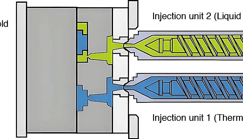
Can you use cold runners for multi-material molding?
Cold runners can be used for multi-material molding in certain configurations, but they are more limited than hot runner systems. Two-shot or overmolding applications can use cold runners in the stationary mold half while the rotating core moves between stations. However, cold runners cannot selectively control material flow to different cavities the way valve-gated hot runner systems can. For complex multi-material applications with three or more materials, or where precise material placement is required, hot runner systems are generally more appropriate.
What gate types work best with cold runner systems?
The most common and effective gate types for cold runner systems are edge gates, submarine (tunnel) gates, and pin gates. Edge gates are the simplest and most economical, machined directly on the parting line. Submarine gates are automatically sheared during ejection, making them ideal for automated production where manual degating is undesirable. Pin gates, used in three-plate molds, provide small-diameter gate vestige and allow gating on any surface. Gate size should be 50–80% of the part wall thickness at the gate location to balance fill quality and degating ease.
-
cold runner system: cold runner system refers to an unheated channel system in an injection mold that conveys molten plastic from the machine nozzle to the cavity gates, solidifying with each cycle. ↩
-
regrind: regrind refers to the process of grinding solidified runners and rejected parts into reusable plastic granules, typically blended with virgin material at 15-20% ratios. ↩
-
Moldflow simulation: Moldflow simulation refers to computer-aided engineering software that simulates plastic flow, cooling, and warpage in injection molds to optimize design before manufacturing. ↩


