 Przejdź do treści
Usługa selektywnego spiekania laserowego (SLS) w druku 3D
Poznaj najwyższej klasy rozwiązania selektywnego spiekania laserowego (SLS) dla skomplikowanych potrzeb druku 3D.
Kompletny przewodnik po druku 3D metodą selektywnego spiekania laserowego (SLS)
Czym jest selektywne spiekanie laserowe (SLS)?
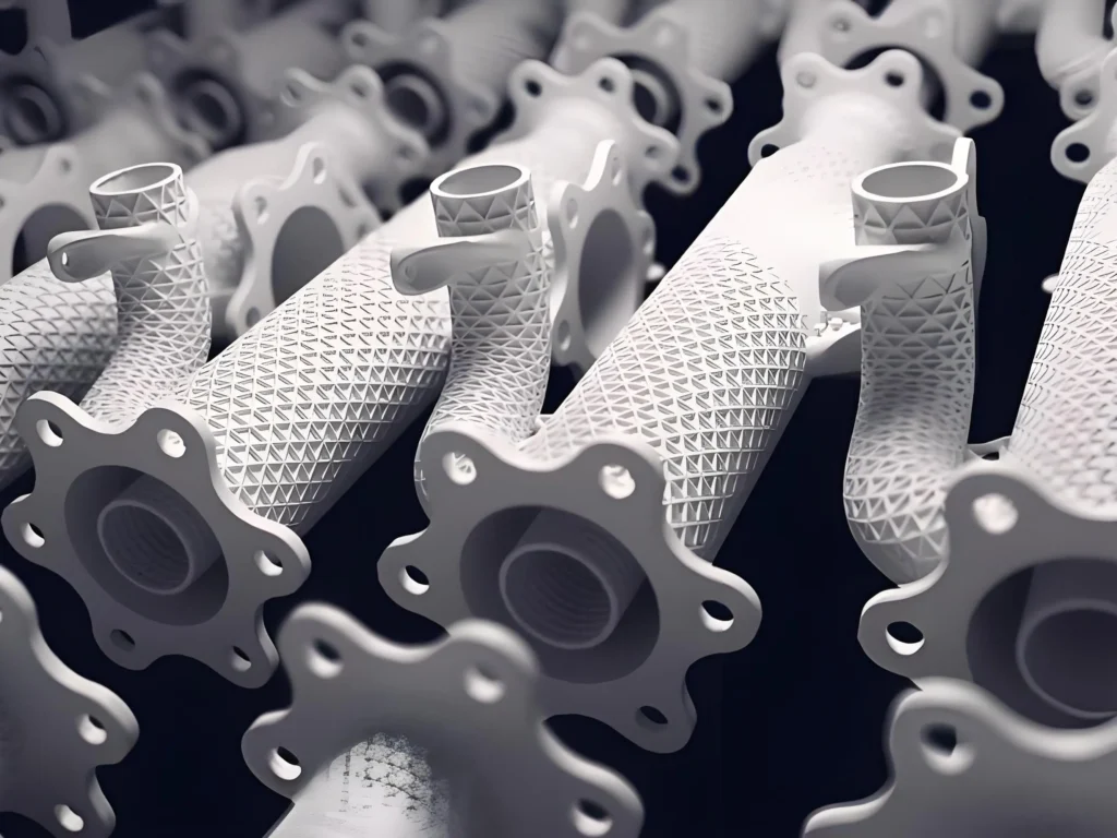
Selektywne spiekanie laserowe (SLS) to zaawansowana technologia produkcji addytywnej (AM), która należy do kategorii fuzja w złożu proszkowym (PBF) rodzina. Wykorzystuje laser o dużej mocy do selektywnego stapiania lub spiekania małych cząstek proszku polimerowego w stały, trójwymiarowy obiekt, warstwa po warstwie.
1. Definicja techniczna:
SLS polega na tworzeniu części z cyfrowego modelu 3D (np. pliku CAD). Proces odbywa się wewnątrz komory zawierającej złoże termoplastycznego proszku, który jest podgrzewany do temperatury tuż poniżej temperatury topnienia materiału. Precyzyjny laser CO₂ skanuje następnie przekrój modelu 3D na powierzchnię złoża proszku, podnosząc temperaturę określonych cząstek do ich temperatury topnienia i powodując ich stopienie. Po ukończeniu warstwy platforma robocza obniża się, nakładana jest nowa warstwa proszku, a proces powtarza się, aż do uformowania całego obiektu.
2. Zasada rdzenia (spiekanie, a nie tylko topienie):
Termin "spiekanie" jest kluczowy. W przeciwieństwie do procesów, które w pełni topią materiał (takich jak selektywne topienie laserowe metali), spiekanie jest procesem termicznym, w którym cząsteczki wiążą się i łączą na poziomie molekularnym bez całkowitego upłynnienia. W ten sposób powstają części, które są nie tylko wytrzymałe, ale także posiadają lekko porowatą mikrostrukturę. Otaczający, niespiekany proszek w komorze roboczej działa jak naturalna, wbudowana struktura nośna dla drukowanej części. Ta samonośna natura jest jedną z najważniejszych zalet technologii SLS.
3. Najważniejsze cechy w skrócie:
Aby szybko zrozumieć, co sprawia, że SLS jest wyjątkowy, należy wziąć pod uwagę następujące cechy:
- Rodzina technologii: Powder Bed Fusion (PBF)
- Materiały podstawowe: Polimery termoplastyczne, najczęściej nylony (PA 11, PA 12).
- Struktury wsparcia: Nie jest wymagany; niewykorzystany proszek podtrzymuje część.
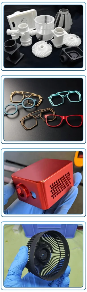
- Właściwości części: Doskonała wytrzymałość mechaniczna, trwałość i odporność na temperaturę. Nadaje się do zastosowań funkcjonalnych.
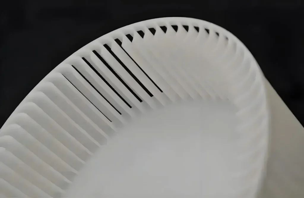
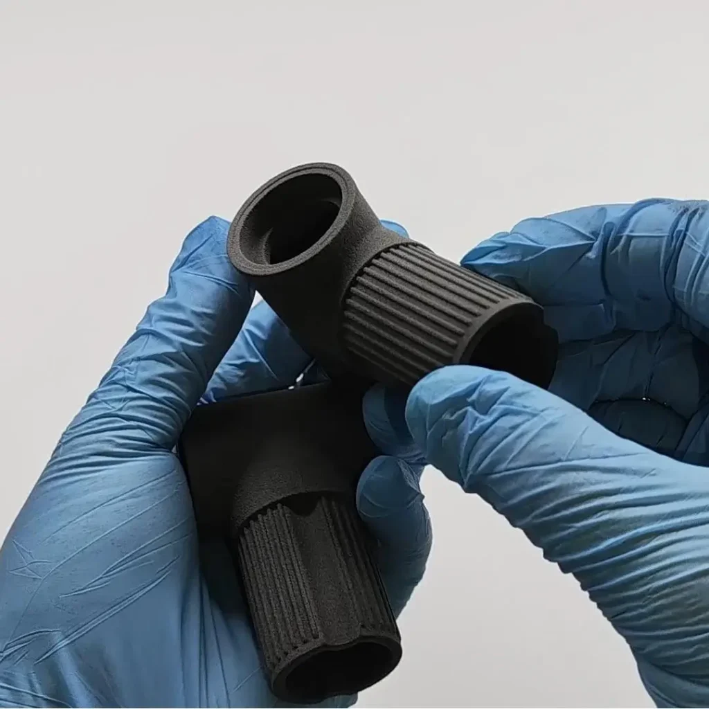
- Wykończenie powierzchni: Matowa, o lekko ziarnistej lub piaszczystej teksturze.
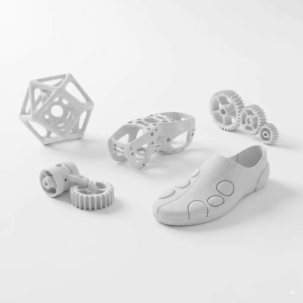
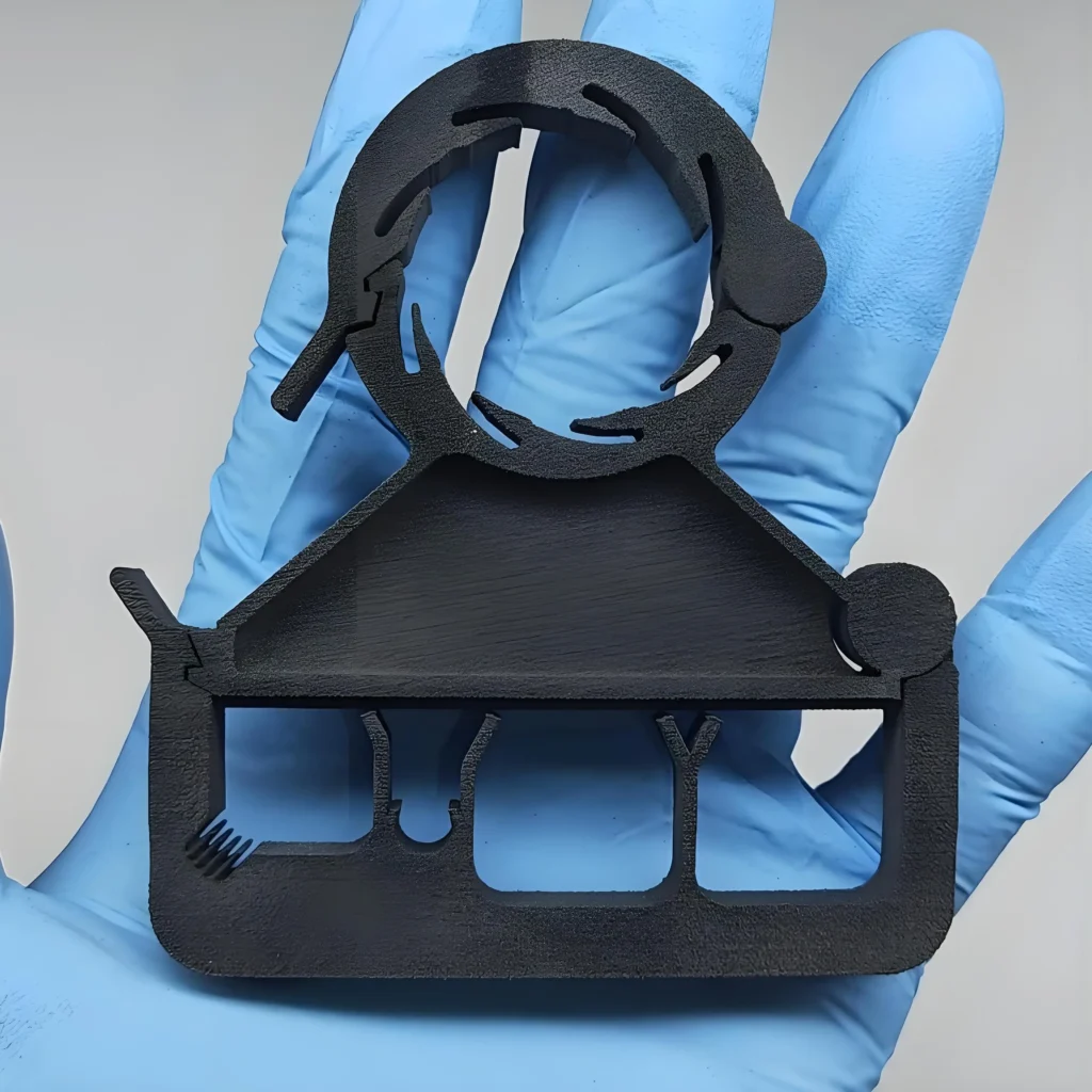
- Główne przypadki użycia: Funkcjonalne prototypowanie, złożone części do zastosowań końcowych, produkcja nisko- i średnioseryjna oraz komponenty o skomplikowanej geometrii, takie jak żywe zawiasy i zatrzaski.
Jak działa druk 3D w technologii SLS?
Zrozumienie procesu SLS wymaga przyjrzenia się zarówno cyfrowemu przepływowi pracy, jak i skomplikowanym operacjom mechanicznym zachodzącym wewnątrz drukarki.
1. Cyfrowy i fizyczny przepływ pracy:
Droga od koncepcji do fizycznej części przebiega standardową ścieżką produkcji cyfrowej:
① Tworzenie modeli 3D: Wszystko zaczyna się od pliku 3D CAD (Computer-Aided Design). Model ten jest następnie eksportowany do formatu nadającego się do druku 3D, zazwyczaj STL (Standard Tessellation Language) lub 3MF (3D Manufacturing Format).
② Krojenie i przygotowanie do budowy: Model 3D jest importowany do specjalistycznego oprogramowania "slicer". Oprogramowanie to cyfrowo "kroi" model na setki lub tysiące cienkich, poziomych warstw. Umożliwia ono również operatorowi orientację i "zagnieżdżanie" wielu części w objętości konstrukcyjnej, aby zmaksymalizować wydajność.
③ Obsługa maszyny: Przygotowany plik jest wysyłany do maszyny SLS, która wykonuje automatyczny proces drukowania.
④ Przetwarzanie końcowe: Po zakończeniu drukowania i chłodzenia części są usuwane z maszyny i poddawane niezbędnym etapom czyszczenia i wykańczania.
2. Proces mechaniczny: Podział warstwa po warstwie:
Magia dzieje się wewnątrz komory roboczej drukarki SLS. Proces ten można podzielić na pięć kluczowych kroków mechanicznych, które są powtarzane dla każdej warstwy.
Krok 1: Przygotowanie i podgrzanie łóżka: Przed rozpoczęciem drukowania cała komora robocza, w tym złoże proszku i otaczający obszar, jest podgrzewana do precyzyjnej temperatury tuż poniżej punktu spiekania polimeru. To wstępne podgrzewanie ma kluczowe znaczenie; minimalizuje zniekształcenia termiczne (wypaczenia) poprzez zmniejszenie gradientu temperatury między spiekanymi i niespiekanymi obszarami. Zapewnia to stabilność wymiarową i dokładność części.
Krok 2: Osadzanie proszku: Mechanizm ponownego powlekania, który może być ostrzem lub wałkiem, porusza się po platformie roboczej, osadzając cienką, jednolitą warstwę proszku (zwykle o grubości 100-150 mikronów) ze zbiornika proszku. Zapewnienie, że warstwa ta jest idealnie płaska i spójna, ma zasadnicze znaczenie dla jakości końcowej części.
Krok 3: Spiekanie laserowe: Jest to rdzeń procesu SLS. Potężny laser CO₂, kierowany przez zestaw dynamicznych luster (galwanometrów), jest kierowany na złoże proszku. Laser śledzi geometrię przekroju bieżącej warstwy, zgodnie z definicją w pliku wycinka. Energia lasera szybko podgrzewa cząstki proszku do temperatury topnienia, powodując ich stopienie w stałą warstwę. Obszary niedotknięte laserem pozostają w postaci sypkiego proszku.
Krok 4: Opuszczanie platformy: Po całkowitym spiekaniu warstwy platforma robocza, na której spoczywa część, obniża się o odległość równą grubości pojedynczej warstwy. Robi to miejsce na kolejną warstwę proszku.
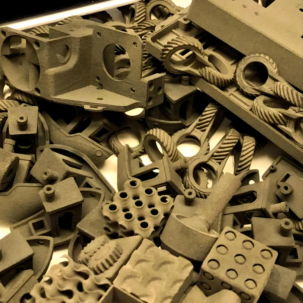
Krok 5: Powtórzenie i zakończenie budowy: Ostrze do ponownego powlekania nakłada świeżą warstwę proszku na poprzednio spiekaną warstwę (krok 2), a laser spieka następny przekrój (krok 3). Ten cykl osadzania proszku, spiekania i opuszczania platformy jest powtarzany, aż każda warstwa części zostanie zbudowana. Gotowe części są teraz zamknięte w solidnym bloku niespiekanego proszku, często nazywanego "ciastem".
3. Faza chłodzenia: Krytyczny, niewidoczny krok:
Jest to jedna z najważniejszych, ale często pomijanych faz procesu SLS. Po spiekaniu ostatniej warstwy, cały placek proszkowy - zawierający gotowe części - musi zostać pozostawiony do powolnego i równomiernego schłodzenia wewnątrz drukarki lub w oddzielnej stacji chłodzącej. Ten kontrolowany proces chłodzenia może zająć wiele godzin (czasami nawet 40-50% całkowitego czasu procesu). Pośpiech na tym etapie spowoduje nierównomierny skurcz i znaczne wypaczenie, niszcząc części.
Jakie materiały są używane w druku SLS?
Wszechstronność SLS wynika w dużej mierze z zakresu wytrzymałych materiałów termoplastycznych, które może przetwarzać. Chociaż nylony są najbardziej rozpowszechnione, dostępne są również inne specjalistyczne polimery.
1. Poliamidy (nylony):
Nylony są najczęściej stosowanymi materiałami w SLS ze względu na ich doskonałą równowagę między wytrzymałością, elastycznością i odpornością termiczną/chemiczną.
① PA 12 (Nylon 12):
PA 12 to złoty standard i najpopularniejszy materiał do SLS.
- Właściwości: Wysoka wytrzymałość, sztywność i doskonała odporność na chemikalia, tłuszcze, oleje i zasady. Wykazuje dobrą stabilność długoterminową i odporność na pękanie naprężeniowe.
- Zastosowania: Idealny do funkcjonalnych prototypów, części końcowych z zatrzaskami, złożonych zespołów i trwałych obudów.
② PA 11 (Nylon 11):
PA 11 jest polimerem pochodzenia biologicznego (wytwarzanym z oleju rycynowego) i jest znany z doskonałej elastyczności i odporności na uderzenia w porównaniu do PA 12.
- Właściwości: Doskonała plastyczność, wysoka udarność i lepsza odporność termiczna. Jest bardziej elastyczny niż PA 12, dzięki czemu nadaje się do części, które muszą się zginać lub wytrzymywać wielokrotne uderzenia.
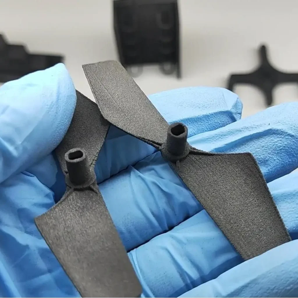
- Zastosowania: Żywe zawiasy, protetyka, sprzęt sportowy, elementy dronów i inne zastosowania wymagające wysokiej wytrzymałości.
Wypełnione poliamidy (materiały kompozytowe):
Aby poprawić określone właściwości, nylony bazowe mogą być mieszane z wypełniaczami.
- Nylon wypełniony włóknem szklanym (PA-GF): Proszek nylonowy jest mieszany z kulkami szklanymi. Kompozyt ten oferuje znacznie wyższą sztywność i odporność termiczną niż standardowy nylon, ale kosztem większej kruchości. Jest on stosowany w częściach, które pracują w wysokich temperaturach lub pod dużym obciążeniem, takich jak komponenty samochodowe, oprzyrządowanie i obudowy.
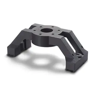
- Nylon wypełniony węglem (PA-CF / Carbonmide): Dzięki zastosowaniu włókien węglowych materiał ten jest niezwykle sztywny, wytrzymały i lekki. Posiada również właściwości rozpraszające ładunki elektrostatyczne (ESD). Zastosowania obejmują wysokowydajne przyrządy, uchwyty, komponenty do sportów motorowych i zrobotyzowane siłowniki końcowe.
- Nylon wypełniony aluminium (Alumide): Mieszanka PA 12 i drobnych cząstek aluminium. Pozwala uzyskać części o metalicznym wyglądzie oraz zwiększonej sztywności i przewodności cieplnej. Jest często używany do prototypów wizualnych, które wymagają metalicznego wyglądu, a także do niestandardowych narzędzi i osprzętu.
2. Termoplastyczny poliuretan (TPU):
TPU to elastyczny, gumopodobny elastomer. Pozwala on SLS na produkcję wytrzymałych, trwałych części, które mogą się zginać i rozciągać.
- Właściwości: Wysoka odporność na ścieranie, wytrzymałość na rozdarcie i elastyczność. Twardość Shore'a może się różnić w zależności od konkretnego gatunku.
- Zastosowania: Uszczelki, uszczelnienia, węże elastyczne, elementy obuwia, obudowy ochronne i elementy tłumiące drgania.
3. Polipropylen (PP):
Polipropylen jest lekkim i wysoce odpornym chemicznie polimerem.
- Właściwości: Doskonała odporność chemiczna (zwłaszcza na kwasy i zasady), niska absorpcja wilgoci, dobra odporność na zmęczenie i spawalność. Jest również biokompatybilny i może być sterylizowany.
- Zastosowania: Systemy płynów, komponenty samochodowe, urządzenia medyczne i pojemniki wymagające odporności chemicznej.
4 Polimery o wysokiej wydajności (PEEK i PEKK):
Materiały te znajdują się w czołówce technologii SLS i wymagają maszyn wysokotemperaturowych.
- Polieteroeteroketon (PEEK) i polieteroketon (PEKK): Należące do rodziny PAEK, są to wysokowydajne polimery o wyjątkowej wytrzymałości mechanicznej, biokompatybilności i odporności na ekstremalne temperatury i agresywne chemikalia. Są one często stosowane jako lekka alternatywa dla metalu.
- Zastosowania: Komponenty lotnicze, implanty medyczne i wysokotemperaturowe części przemysłowe.
Jakie są etapy procesu drukowania SLS?
W tej sekcji przedstawiono kompleksowy przepływ pracy operacyjnej, zapewniając praktyczny widok z perspektywy operatora lub dostawcy usług.
Krok 1: Przygotowanie modelu cyfrowego:
Proces rozpoczyna się od sfinalizowania modelu 3D CAD. Model ten musi być "wodoszczelny" (zamknięta, kolektorowa bryła) i wolny od błędów geometrycznych. Jest on następnie eksportowany jako plik STL lub 3MF.
Krok 2: Konfiguracja kompilacji i zagnieżdżanie:
Plik jest ładowany do oprogramowania do przygotowania wydruku drukarki. Tutaj wykonywane są dwie krytyczne czynności:
- Orientacja: Część jest zorientowana tak, aby zoptymalizować wytrzymałość, wykończenie powierzchni i dokładność. Na przykład, ustawienie płaskiej powierzchni równolegle do płyty roboczej pozwoli uniknąć "schodkowania".
- Zagnieżdżanie: Ponieważ SLS nie wymaga konstrukcji wsporczych, wiele części może być gęsto upakowanych razem w trzech wymiarach w objętości wydruku. Takie "zagnieżdżanie" znacznie zwiększa przepustowość i zmniejsza koszt pojedynczej części, dzięki czemu SLS jest wysoce wydajny w produkcji seryjnej.
Krok 3: Konfiguracja maszyny i ładowanie proszku:
Operator przygotowuje maszynę SLS. Obejmuje to czyszczenie komory wydruku z poprzedniego przebiegu i ładowanie jej proszkiem polimerowym. Kluczową koncepcją jest tutaj częstotliwość odświeżania - mieszanka świeżego (pierwotnego) proszku i proszku z recyklingu z poprzedniego zadania drukowania. Typowa częstotliwość odświeżania wynosi 50%, co oznacza, że konstrukcja jest wykonana z 50% pierwotnego proszku i 50% proszku z recyklingu. Ma to kluczowe znaczenie zarówno dla opłacalności, jak i utrzymania właściwości materiału.
Krok 4: Zautomatyzowany cykl drukowania i chłodzenia:
Po rozpoczęciu budowy proces jest w pełni zautomatyzowany. Maszyna nagrzewa się, osadza i spieka proszek warstwa po warstwie, a na koniec inicjuje długi, kontrolowany cykl chłodzenia. Cały ten etap może trwać od 12 godzin do ponad dwóch dni, w zależności od rozmiaru i gęstości wydruku.
Krok 5: Breakout i depowdering:
Po zakończeniu cyklu chłodzenia komora robocza jest otwierana, a stały blok proszku ("ciasto") jest przenoszony do stacji odłamywania. Operator ostrożnie wydobywa gotowe części z luźnego, niespieczonego proszku. Może to być niechlujny, ręczny proces. Otaczający proszek jest zbierany do recyklingu.
Krok 6: Czyszczenie strumieniowo-ścierne:
Nowo uwolnione części są nadal pokryte warstwą pozostałego proszku. Są one umieszczane w komorze do piaskowania lub śrutowania, gdzie wysokociśnieniowy strumień drobnych mediów (takich jak szklane kulki lub plastikowe granulki) jest używany do usuwania pozostałego proszku i tworzenia gładkiego, jednolitego, matowego wykończenia powierzchni.
Krok 7: Zaawansowane przetwarzanie końcowe (opcjonalnie):
W zależności od zastosowania, części mogą być poddawane dodatkowym etapom wykańczania, takim jak barwienie, wygładzanie parowe, malowanie lub powlekanie w celu poprawy estetyki, jakości powierzchni lub określonych właściwości funkcjonalnych.
Jakie są kluczowe parametry wpływające na jakość SLS?
Jakość części SLS nie jest przypadkowa; jest wynikiem starannej kontroli szerokiego zakresu parametrów procesu.
1. Parametry związane z materiałem:
- Rozmiar i rozkład cząstek: Rozmiar i kształt cząstek proszku wpływają na płynność proszku i gęstość upakowania, co z kolei wpływa na gęstość końcowej części i wykończenie powierzchni.
- Częstotliwość odświeżania proszku: Stosunek proszku pierwotnego do proszku z recyklingu. Użycie zbyt dużej ilości proszku z recyklingu może prowadzić do pogorszenia właściwości mechanicznych i niskiej jakości powierzchni, ponieważ proszek ulega degradacji termicznej przy każdym cyklu drukowania.
2. Parametry związane z procesem (w drukarce):
① Parametry termiczne:
- Temperatura łóżka: Temperatura złoża proszku, utrzymywana tuż poniżej punktu spiekania. Zbyt niska temperatura może powodować wypaczenia ("zwijanie się"). Jeśli jest zbyt wysoka, może prowadzić do niepożądanego spiekania otaczającego proszku ("wzrost").
- Temperatura komory: Temperatura otoczenia w obszarze roboczym. Stabilna i jednolita temperatura ma zasadnicze znaczenie dla spójności części.
② Parametry lasera:
- Gęstość energii: Jest to najbardziej krytyczny parametr, definiowany jako ilość energii lasera dostarczanej na jednostkę powierzchni. Jest to funkcja mocy lasera, prędkości skanowania i odstępu między skanami.
- Moc lasera (waty): Wyższa moc pozwala na szybsze spiekanie, ale musi być zrównoważona, aby uniknąć przegrzania lub spalenia materiału.
- Prędkość skanowania (mm/s): Prędkość, z jaką wiązka lasera porusza się po proszku.
- Odstęp skanowania (odległość kreskowania): Odległość między sąsiednimi liniami skanowania laserowego. Węższe odstępy skutkują gęstszą częścią, ale dłuższym czasem budowy.
- Optymalna gęstość energii zapewnia całkowitą fuzję między cząstkami i warstwami bez degradacji polimeru.
③ Parametry warstwy:
- Grubość warstwy: Wysokość każdej pojedynczej warstwy, zazwyczaj około 0,1 mm (100 mikronów). Cieńsze warstwy zapewniają lepsze wykończenie powierzchni i drobniejsze szczegóły, zwłaszcza na zakrzywionych lub pochylonych powierzchniach, ale znacznie wydłużają czas drukowania.
3. Zbuduj parametry układu:
- Orientacja na część: Sposób umieszczenia części w komorze roboczej. Wpływa to na jakość powierzchni (efekt schodków na powierzchniach kątowych), właściwości mechaniczne (części są najmocniejsze wzdłuż płaszczyzny X-Y) i ryzyko wypaczenia.
- Gęstość gniazdowania: Podczas gdy zagnieżdżanie zwiększa wydajność, zbyt gęste upakowanie części może powodować powstawanie lokalnych punktów ciepła, potencjalnie wpływając na dokładność pobliskich komponentów.
Jakie są zalety druku 3D w technologii SLS?
SLS jest preferowaną technologią dla wielu zastosowań ze względu na unikalną kombinację korzyści.
1. Swoboda projektowania: Brak konieczności stosowania konstrukcji wsporczych:
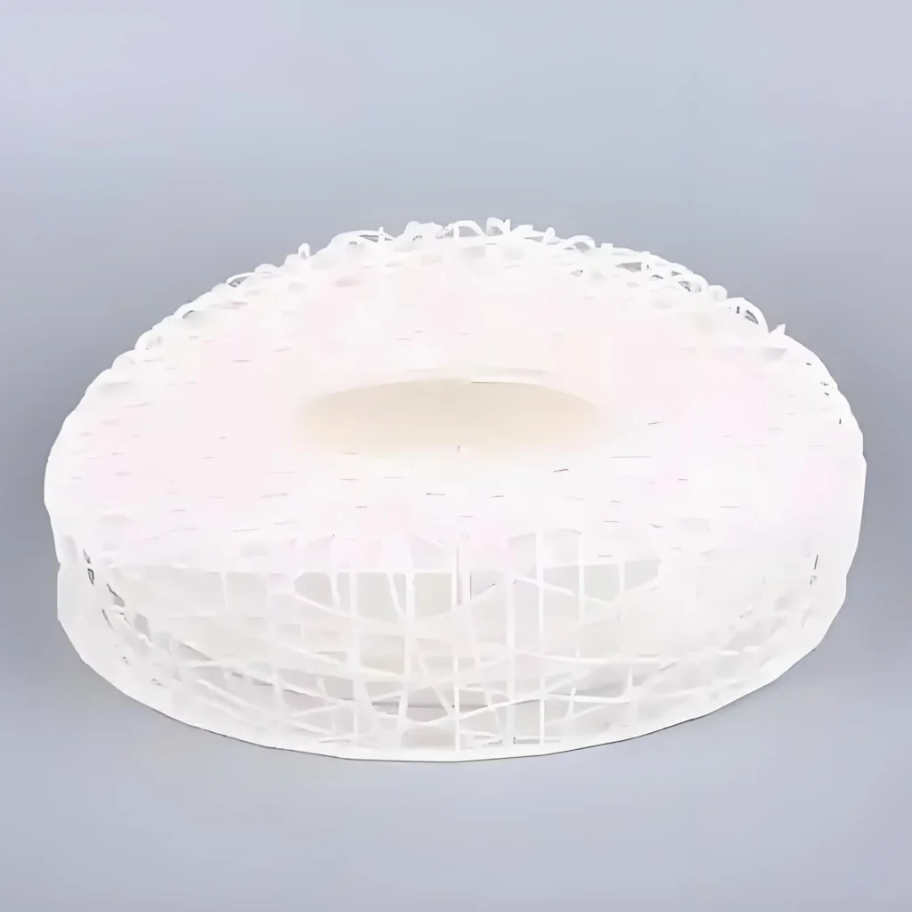
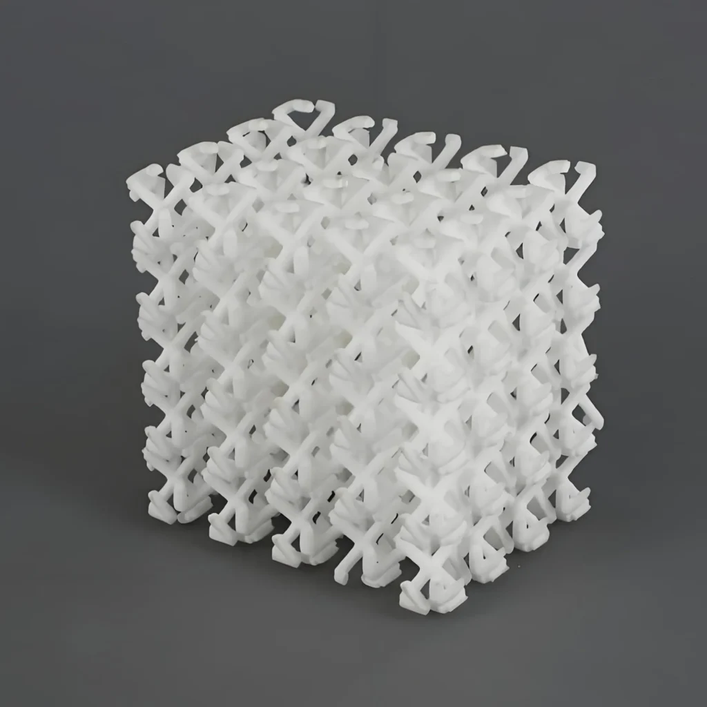
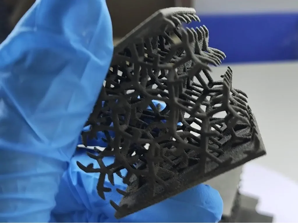
Jest to prawdopodobnie najważniejsza zaleta SLS. Niespiekany proszek w objętości wydruku zapewnia pełne wsparcie dla części podczas drukowania. Pozwala to na tworzenie niezwykle złożonych geometrii, w tym wewnętrznych kanałów, podcięć i skomplikowanych struktur kratowych, które są niemożliwe lub bardzo trudne do wytworzenia innymi metodami. Eliminuje to również etap usuwania podpór po procesie drukowania, oszczędzając czas i pracę.
2. Doskonałe właściwości mechaniczne:
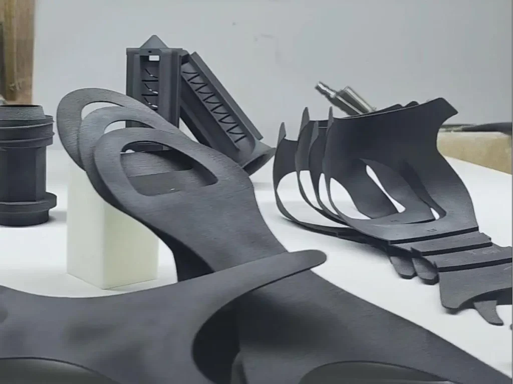
Części SLS, szczególnie te wykonane z nylonu, znane są z wysokiej wytrzymałości, sztywności i trwałości. Zachowują się podobnie do części formowanych wtryskowo, dzięki czemu nadają się do rygorystycznych testów funkcjonalnych i jako części produkcyjne do użytku końcowego. Są odporne na uderzenia, wysoką temperaturę i działanie substancji chemicznych.
3. Wysoka wydajność i skalowalność:
Zdolność do zagnieżdżania dziesiątek, a nawet setek części w jednym cyklu produkcyjnym sprawia, że SLS jest wysoce wydajny w przypadku niskich i średnich serii produkcyjnych. Maksymalizuje to wykorzystanie objętości produkcyjnej maszyny i znacznie obniża koszt pojedynczej części w porównaniu do drukowania części pojedynczo.
4. Złożona geometria i skomplikowane detale:
Ponieważ nie ma podpór ograniczających projekt, inżynierowie mogą tworzyć części zoptymalizowane pod kątem wydajności, a nie możliwości produkcji. Obejmuje to takie funkcje, jak żywe zawiasy, połączenia zatrzaskowe i skonsolidowane zespoły, w których wiele komponentów jest drukowanych jako pojedyncza, złożona część.
5. Dobra różnorodność materiałów:
SLS oferuje szeroką gamę tworzyw termoplastycznych klasy inżynieryjnej, od elastycznych TPU po sztywne, wypełnione węglem nylony i wysokowydajne PEEK. Dzięki temu technologia ta może służyć do szerokiej gamy zastosowań w różnych branżach.
Niestandardowy druk 3D SLS dla mocnych i złożonych części
Uzyskaj trwałe, szczegółowe części dzięki naszym usługom selektywnego spiekania laserowego (SLS) w druku 3D.
Kompletny przewodnik po druku 3D metodą selektywnego spiekania laserowego (SLS)
Jakie są ograniczenia SLS w porównaniu do innych metod druku 3D?
Pomimo wielu zalet, SLS nie jest idealnym rozwiązaniem dla każdego zastosowania. Ma kilka ograniczeń, które należy wziąć pod uwagę.
1. Wykończenie powierzchni i porowatość:
Części SLS mają naturalnie matowe, ziarniste wykończenie powierzchni ze względu na charakter utrwalania cząstek proszku. Powierzchnia jest również lekko porowata. Chociaż jest to akceptowalne w przypadku wielu funkcjonalnych części, zastosowania wymagające idealnie gładkiej, kosmetycznej powierzchni będą wymagały rozległej obróbki końcowej (np. wygładzania parą). Technologie takie jak SLA lub Material Jetting oferują znacznie gładsze wykończenie.
2. Wyższy koszt początkowy:
Maszyny SLS stanowią znaczną inwestycję kapitałową, często kosztując znacznie ponad $100,000 dla systemów klasy przemysłowej. Koszty materiałów są również wyższe niż w przypadku filamentów FDM lub żywic SLA. To sprawia, że bariera wejścia na rynek jest wyższa dla mniejszych firm.
3. Dłuższy czas realizacji:
Całkowity czas procesu SLS może być długi. Wynika to nie tylko z samego czasu drukowania, ale przede wszystkim z obowiązkowego, wydłużonego okresu chłodzenia, który może trwać do 12-24 godzin. Sprawia to, że SLS jest mniej odpowiedni do szybkich, jednorazowych prototypów w porównaniu do FDM lub SLA.
4. Złożoność obsługi materiałów i recyklingu:
Praca z drobnymi proszkami polimerowymi wymaga kontrolowanego środowiska i środków ochrony osobistej. Co więcej, zarządzanie cyklem życia proszku - śledzenie zużycia, obliczanie częstotliwości odświeżania i przesiewanie proszku z recyklingu - zwiększa złożoność operacyjną.
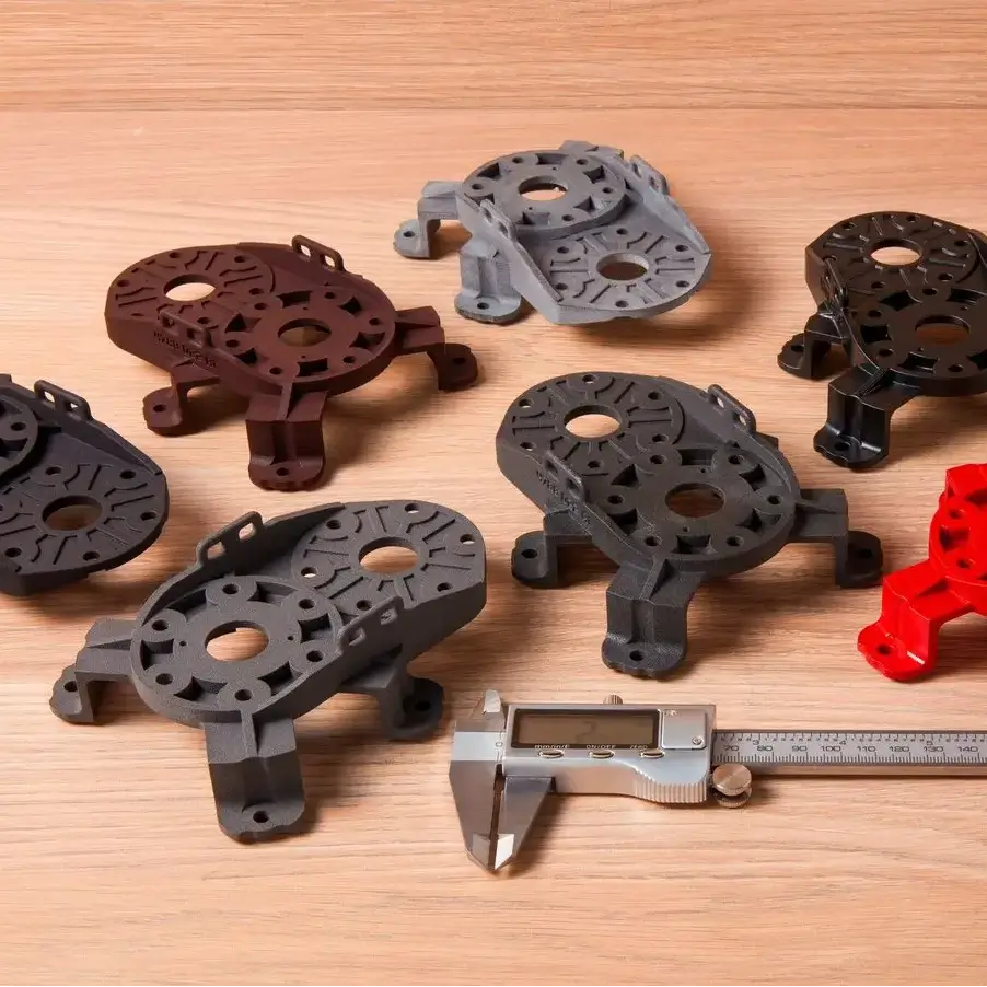
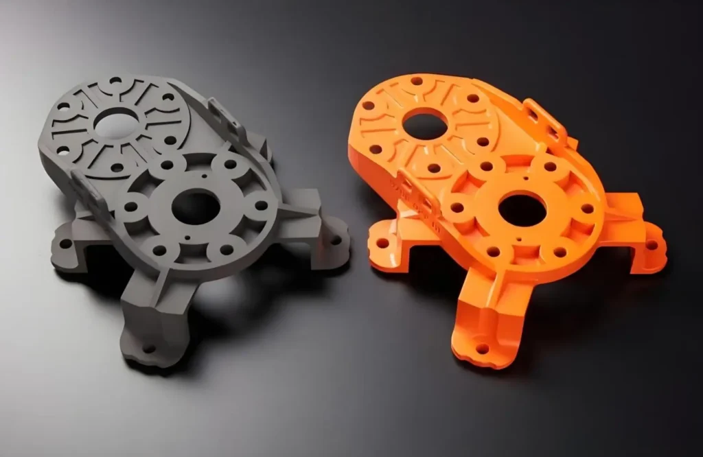
5. Ograniczone opcje kolorów:
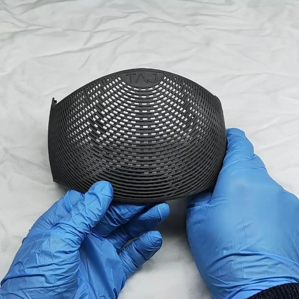
Części SLS są zazwyczaj drukowane w jednym kolorze, zwykle białym, szarym lub czarnym, w zależności od materiału. Uzyskanie koloru wymaga dodatkowego etapu obróbki końcowej, takiego jak barwienie, co zwiększa czas i koszty. Technologie takie jak Material Jetting lub Binder Jetting oferują możliwość drukowania w pełnym kolorze.
Jakie są typowe zastosowania SLS?
Unikalne właściwości części SLS doprowadziły do ich zastosowania w wielu gałęziach przemysłu w wymagających aplikacjach.
1. Prototypowanie:
① Prototypy funkcjonalne:
Jest to kwintesencja zastosowania SLS. Firmy wykorzystują SLS do tworzenia prototypów o wysokiej wierności, które można poddać testom w świecie rzeczywistym. Ponieważ właściwości mechaniczne są tak zbliżone do końcowych części produkcyjnych, inżynierowie mogą niezawodnie testować formę, dopasowanie i funkcjonalność.
- Przykłady: Obudowy dla elektroniki, zespoły zatrzaskowe, badania ergonomiczne i testy przepływu powietrza w kanałach.
② Żywe zawiasy i zatrzaski:
Trwałość i elastyczność materiałów takich jak PA 11 i PA 12 sprawiają, że są one idealne do prototypowania projektów, które obejmują żywe zawiasy lub wielokrotnego użytku zatrzaskowe zamknięcia.
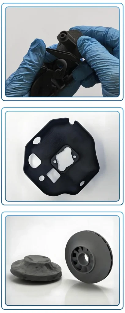
2. Części końcowe i produkcja małoseryjna:
SLS wykroczył poza prototypowanie i jest obecnie realną metodą produkcji. Przykłady:
- Przemysł lotniczy i motoryzacyjny: Kanały powietrzne, wsporniki, niestandardowe elementy wewnętrzne i nadwozia UAV (dronów). Lekkie i wytrzymałe właściwości są idealne.
- Urządzenia medyczne: Niestandardowe protezy, wkładki ortopedyczne, prowadnice chirurgiczne i obudowy sprzętu medycznego. Wiele materiałów SLS jest biokompatybilnych.
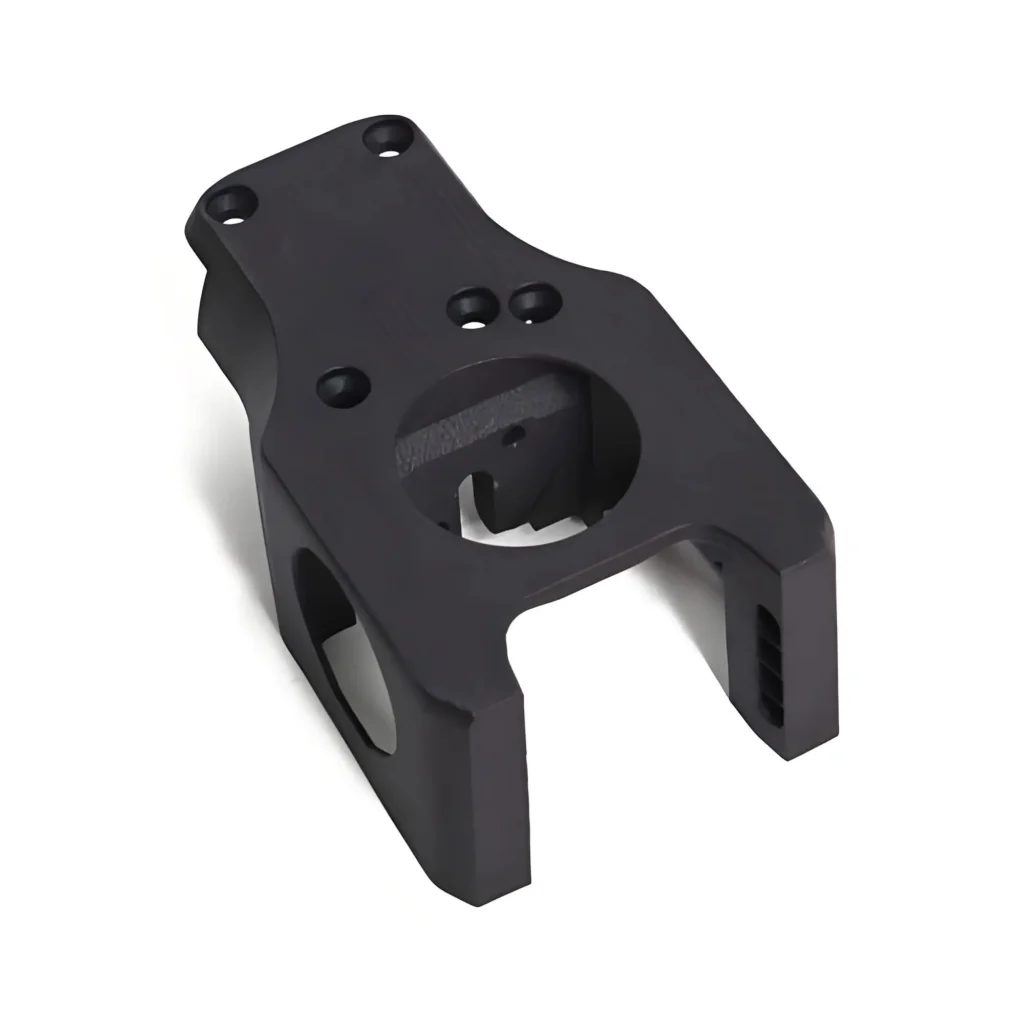
- Robotyka i automatyka: Niestandardowe chwytaki (oprzyrządowanie na końcu ramienia), przyrządy, uchwyty i obudowy do systemów zrobotyzowanych.
- Oprzyrządowanie: Tworzenie niestandardowych przyrządów i uchwytów dla linii produkcyjnych w celu poprawy wydajności i dokładności.
3. Towary konsumpcyjne:
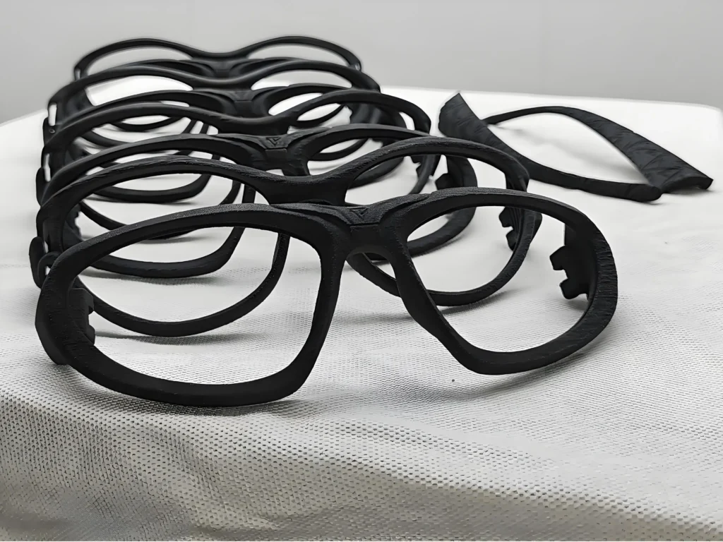
- Przykłady: Wysokiej klasy niestandardowe oprawki do okularów, etui ochronne do elektroniki, komponenty do sprzętu sportowego i spersonalizowane produkty.
Jakie są etapy obróbki końcowej części drukowanych metodą SLS?
Obróbka końcowa jest obowiązkowym etapem w procesie SLS, aby przekształcić surowy wydruk w część użytkową.
1. Podstawowa obróbka końcowa (standardowa):
Kroki te są wykonywane na prawie wszystkich częściach SLS.
- Podział części i depowdering: Pierwszym krokiem po schłodzeniu jest ręczne wydobycie części z placka niespieczonego proszku. Sprężone powietrze jest często używane do wydmuchiwania większości luźnego proszku.
- Media Blasting: Części są następnie umieszczane w komorze śrutowniczej. Strumień mediów (np. szklanych kulek, plastikowych kulek lub tlenku glinu) jest wystrzeliwany na części w celu usunięcia wszelkich pozostałości stopionego proszku i stworzenia jednolitego, czystego, matowego wykończenia powierzchni.
2. Wtórna i estetyczna obróbka końcowa (opcjonalnie):
Kroki te są stosowane w celu poprawy wyglądu lub funkcjonalności części.
- Barwienie: Najpopularniejsza metoda dodawania koloru. Porowata natura części SLS pozwala im bardzo dobrze wchłaniać barwnik. Części są zanurzane w gorącej kąpieli barwiącej, co skutkuje bogatym, głębokim kolorem, który wnika w powierzchnię.
- Chemiczne wygładzanie oparów: Proces, w którym części są wystawiane na działanie odparowanego rozpuszczalnika, który lekko topi i przepływa przez zewnętrzną powierzchnię. Uszczelnia to porowatość części, czyniąc ją wodoszczelną i hermetyczną oraz tworzy gładkie, półbłyszczące wykończenie porównywalne z formowaniem wtryskowym.
- Wykończenie bębnowe / wibracyjne: W przypadku partii mniejszych części można je umieścić w bębnie z nośnikiem ceramicznym lub plastikowym. Działanie wibracyjne wygładza powierzchnię i zaokrągla ostre krawędzie.
- Malowanie i powlekanie: Aby uzyskać określone kolory lub wykończenia ochronne, części SLS można zagruntować i pomalować. Powłoki takie jak Cerakote mogą być stosowane w celu zwiększenia trwałości i odporności chemicznej.
Jak poprawić wykończenie powierzchni i dokładność wymiarową w SLS?
Osiągnięcie najwyższej jakości z SLS wymaga połączenia optymalizacji procesu wstępnego, prawidłowej obsługi maszyny i przetwarzania końcowego.
1. Optymalizacja wykończenia powierzchni:
① Optymalizacja procesu wstępnego:
- Orientacja części: Unikaj efektu "schodkowania", ustawiając zakrzywione lub pochylone powierzchnie z dala od bezpośredniego kąta 45 stopni względem płyty roboczej. Ukierunkowanie krytycznych powierzchni w górę lub w dół często daje najlepsze rezultaty.
- Mniejsza grubość warstwy: Użycie cieńszej warstwy (np. 0,08 mm zamiast 0,12 mm) zmniejszy widoczność linii warstwy, ale wydłuży czas drukowania.
② Rozwiązania postprocesowe:
- Obróbka strumieniowo-ścierna: Standardowa metoda zapewniająca jednolite matowe wykończenie.
- Vapor Smoothing: Najskuteczniejsza metoda uzyskania gładkiej powierzchni przypominającej formę wtryskową. Jest to najlepszy wybór do zastosowań wymagających uszczelnionych, łatwych do czyszczenia powierzchni.
2. Zwiększenie dokładności wymiarowej:
① Kalibracja maszyny: Niezbędna jest regularna kalibracja kluczowych parametrów maszyny. Obejmuje to dostrojenie współczynników skalowania X-Y lasera w celu skompensowania wszelkich niedokładności systemowych i dostosowanie przesunięcia wiązki laserowej.
② Rozliczanie skurczu i wypaczenia:
- Zarządzanie temperaturą: Upewnij się, że systemy grzewcze maszyny działają prawidłowo, aby utrzymać stabilny i jednolity profil temperatury. Jest to pierwsza linia obrony przed wypaczeniami.
- Orientacja części: Ukierunkowanie długich, płaskich części pionowo, a nie poziomo, może czasami zmniejszyć ryzyko wypaczenia.
- Kompensacja oprogramowania: Zaawansowane oprogramowanie może zastosować współczynniki skalowania do modelu, aby przeciwdziałać naturalnemu skurczowi materiału podczas chłodzenia.
③ Projektowanie na potrzeby wytwarzania przyrostowego (DfAM):
- Grubość ścianki: Przestrzegaj wytycznych dotyczących minimalnej grubości ścianki (zazwyczaj 0,8-1,0 mm), aby zapewnić wytrzymałość części i pomyślne drukowanie.
- Rozmiary otworów: Małe otwory mają tendencję do kurczenia się podczas spiekania. Powszechną praktyką jest projektowanie ich nieco ponadwymiarowych lub planowanie wywiercenia ich do ostatecznego wymiaru po wydrukowaniu.
- Wytłaczane/wybijane szczegóły: Upewnij się, że tekst i drobne szczegóły są wystarczająco duże, aby mogły być wyraźnie rozpoznane przez laser i nie zostały utracone podczas piaskowania.
Jak SLS wypada w porównaniu z SLA, MJF i FDM?
Wybór odpowiedniej technologii druku 3D zależy od konkretnych wymagań danego projektu. Oto jak SLS wypada na tle innych popularnych metod.
1. Tabela porównawcza:
| Cecha | Selektywne spiekanie laserowe (SLS) | Stereolitografia (SLA) | Multi Jet Fusion (MJF) | Modelowanie topionego osadzania (FDM) |
|---|---|---|---|---|
| Technologia | Fuzja w łożu proszkowym (laser) | Fotopolimeryzacja w kadzi (laser/projektor) | Fuzja złoża proszkowego (termiczna + środki) | Wytłaczanie materiału (filament) |
| Materiały podstawowe | Nylony (PA11, PA12), TPU, PP | Żywice fotopolimerowe (standardowe, wytrzymałe, elastyczne, odlewane) | Nylony (PA12, PA11), TPU, PP | Tworzywa termoplastyczne (PLA, ABS, PETG, PC, Nylon) |
| Dokładność wymiarowa | Wysoki (±0,25 mm) | Bardzo wysoka (±0,1 mm) | Wysoki (±0,25 mm) | Średni do niskiego (±0,5 mm) |
| Wykończenie powierzchni | Matowy, ziarnisty, porowaty | Bardzo gładka, linie warstw ledwo widoczne | Gładki, nieco mniej ziarnisty niż SLS | Widoczne linie warstw, szorstkie |
| Wydajność/Szybkość | Wysoka (zagnieżdżanie części), ale długie cykle chłodzenia. | Średni (zależy od wysokości i przekroju części). | Bardzo wysoka (szybkie drukowanie, krótsze cykle chłodzenia niż SLS). | Wolno (drukuje części jedna po drugiej). |
| Koszt | Wysoki koszt maszyny, średni koszt części ze względu na zagnieżdżanie. | Średni koszt maszyny, niski lub średni koszt części. | Wysoki koszt maszyny, niski koszt części dzięki prędkości i zagnieżdżaniu. | Niskie koszty maszyn i materiałów. |
| Kluczowe mocne strony | Brak podpór, trwałe części funkcjonalne, złożone geometrie. | Doskonała szczegółowość i wykończenie powierzchni, idealne do modeli wizualnych. | Wysoka prędkość, niski koszt części do produkcji, dobre właściwości mechaniczne. | Niski koszt, szeroka gama materiałów, łatwa obsługa. |
| Kluczowe słabości | Ziarnista powierzchnia, długi czas realizacji, obsługa proszków. | Wymaga konstrukcji wsporczych, części mogą być kruche, wrażliwe na promieniowanie UV. | Ograniczone materiały, ziarnista powierzchnia (choć lepsza niż SLS). | Niska dokładność i rozdzielczość, widoczne linie warstw, słabsza oś Z. |
2. SLS vs. SLA:
Wybierz SLS dla trwałych, funkcjonalnych prototypów i części do zastosowań końcowych, które muszą wytrzymywać obciążenia mechaniczne. Wybierz SLA gdy potrzebujesz wyjątkowego wykończenia powierzchni, drobnych szczegółów i dokładności modeli wizualnych, form lub wzorów.
3. SLS vs. MJF:
SLS i MJF są bezpośrednimi konkurentami. Obie są technologiami syntezy w złożu proszkowym, idealnymi do produkcji funkcjonalnych części nylonowych.
- MJF jest ogólnie szybszy i może zaoferować Niższy koszt na część w scenariuszach produkcyjnych, ze względu na proces druku termicznego i bardziej wydajne zarządzanie ciepłem.
- SLS często zapewnia nieco "bielszą" lub jaśniejszą surową część i ma dłuższe doświadczenie z potencjalnie szerszą gamą specjalistycznych materiałów dostępnych na niektórych platformach. Wykończenie powierzchni części MJF jest generalnie bardziej drobnoziarniste niż SLS.
4. SLS vs. FDM:
Wybierz SLS gdy potrzebujesz wytrzymałych części o jakości produkcyjnej i złożonej geometrii, których FDM nie jest w stanie wyprodukować bez rozbudowanych struktur wsporczych. Wybierz FDM do tanich, wczesnych modeli koncepcyjnych, prostych przyrządów lub gdy potrzebna jest szeroka gama kolorów i materiałów (takich jak PLA lub PETG) szybko i niedrogo.
Najczęściej zadawane pytania dotyczące druku 3D w technologii SLS
Tak, części SLS, zwłaszcza te wykonane z nylonu, mają doskonałe właściwości mechaniczne, w tym wysoką wytrzymałość na rozciąganie i odporność na uderzenia. Są to jedne z najmocniejszych polimerowych opcji druku 3D i nadają się do wymagających zastosowań funkcjonalnych i części końcowych.
W stanie surowym, po piaskowaniu, części SLS są lekko porowate i z czasem będą wchłaniać wilgoć. Nie są uważane za wodoodporne. Można je jednak uczynić wodoodpornymi i hermetycznymi poprzez etapy przetwarzania końcowego, takie jak chemiczne wygładzanie oparów lub nakładanie powłoki epoksydowej.
Na koszt ma wpływ kilka czynników: objętość części, liczba części zagnieżdżonych w kompilacji, użyty materiał i wymagana obróbka końcowa. Podczas gdy początkowa inwestycja w maszynę jest wysoka, koszt jednej części może być konkurencyjny dla serii produkcyjnych o niskiej i średniej wielkości ze względu na wydajne zagnieżdżanie i minimalną robociznę.
Współczynnik odświeżania to procent świeżego, pierwotnego proszku, który musi zostać zmieszany z przetworzonym, niespiekanym proszkiem z poprzedniej kompilacji, aby utworzyć nową partię. Typowy współczynnik to 50/50. Jest to ważne, ponieważ proszek znajdujący się w ogrzewanej komorze ulega nieznacznej degradacji, a jego ponowne użycie bez dodania świeżego proszku skutkowałoby niską jakością części. Zarządzanie częstotliwością odświeżania jest kluczem do kontrolowania kosztów i utrzymywania stałych właściwości materiału.
Termin "SLS" jest prawie wyłącznie używany do drukowania polimerów (tworzyw sztucznych). Równoważny proces dla metali nazywa się Bezpośrednie spiekanie laserowe metali (DMLS) lub Selektywne topienie laserowe (SLM). Chociaż podstawowa zasada wykorzystania lasera do stapiania proszku jest podobna, maszyny DMLS/SLM wykorzystują znacznie mocniejsze lasery i działają w znacznie wyższych temperaturach w całkowicie obojętnej atmosferze do przetwarzania proszków metali, takich jak aluminium, tytan i stal nierdzewna.

Zbliżenie na kolorowe plastikowe klocki konstrukcyjne w różnych barwach, w tym fioletowe, niebieskie, zielone i żółte, ułożone jeden na drugim.
Kluczowe wnioski – Wybór materiału i optymalizacja grubości ścianki są głównymi czynnikami wpływającymi na redukcję kosztów części. – Inwestowanie w wyższej jakości narzędzia (klasa 101/102) może obniżyć długoterminowe koszty jednostkowe poprzez

Family Molds vs. MUD Systems: Which Strategy Best Manages Multi-Part Injection Molding Projects?
Przeczytaj więcej o tym, Jak Poprawić Precyzję Form Wtryskowych?

Co to jest maszyna do formowania wtryskowego z dużą prędkością?
Key Takeaways – A high-speed injection molding machine is defined by injection speed4s of 300–600 mm/s and clamp speeds exceeding 500 mm/s, compared to 100–200 mm/s for standard machines—enabling cycle
Dostarczane rozwiązania optymalizacyjne Za darmo
- Dostarczanie informacji zwrotnych i rozwiązań optymalizacyjnych
- Optymalizacja struktury i redukcja kosztów formowania
- Bezpośrednia rozmowa z inżynierami jeden na jeden

