 Overslaan naar inhoud

core1 en cavity2 sound like simple mold terms, but they decide more than the basic shape of a plastic part. They influence gate access, deellijn3 location, ejector marks, texture, flash risk, cooling balance, shrinkage direction, and whether a part can be released without damage.
If you only ask, “what is the core and what is the cavity?” you get a textbook answer. If you ask how the two halves control cost, defects, tooling life, and production stability, you get a useful engineering answer for spuitgieten en spuitgietvorm projecten.
This guide explains the core-cavity relationship in plain language, then turns it into a practical design and buyer checklist. The goal is to help you review a mold concept before steel is cut, because late changes to the core or cavity are rarely cheap.
- Core forms internal geometry; cavity forms outside shape.
- Parting line choice affects flash, appearance, and release.
- Cooling balance is as important as steel accuracy.
- Core-cavity mismatch often creates defects and rework.
- Buyers should review mold layout before tooling approval.
What are core and cavity in injection molding?
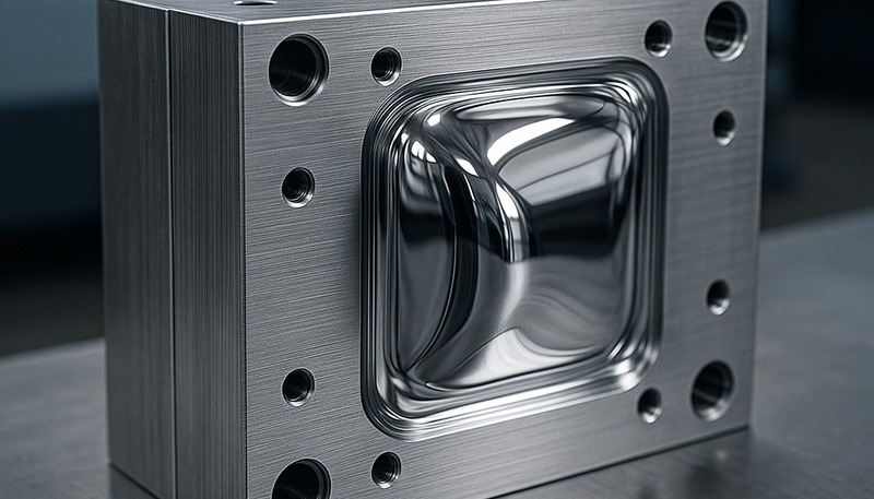
Core and cavity are the two mold-forming sides that create the final plastic part shape. The cavity usually forms the outside or visible surface, while the core usually forms internal surfaces, holes, bosses, ribs, undercuts, or the side that needs ejection support.
In a simple box-shaped part, the cavity may create the outside shell and cosmetic face, while the core creates the inside hollow space. In a more complex part, several inserts, lifters, sliders, or removable cores may work together. That is why real mold design is not just a male-half and female-half drawing.
In our experience, the best first review question is simple: which side controls the functional surface? If the cosmetic face, sealing face, clip feature, screw boss, or assembly datum is assigned to the wrong side, the mold may still make a part, but production quality becomes harder to control.
“Core and cavity decisions affect both part shape and production risk.”Echt
The mold split controls how plastic fills, where air escapes, how the part cools, where ejector force is applied, and which surface shows parting-line or flash marks.
“The cavity is always the fixed side and the core is always the moving side.”Vals
Many molds follow that convention, but complex tools can use inserts, sliders, lifters, unscrewing cores, and other mechanisms. Function and release strategy matter more than a simple label.
How do core and cavity shape a molded plastic part?
The core is used to form internal or raised features, while the cavity is used to form the outside contour and visible face. Molten plastic flows into the gap between these surfaces, cools against the steel, and becomes the final part geometry after the mold opens.
That gap is not just empty space. It defines wall thickness, rib depth, boss height, shutoff angle, gate access, venting, cooling distance, and ejection direction. A small mismatch between the core and cavity can create uneven walls, sink marks, flash, short shots, drag marks, or dimensional variation.
Wall thickness is the first thing to check. If the core sits too close to the cavity, the part may short shot or become weak. If the core sits too far away, the wall gets thick, cooling slows down, and sink marks appear near ribs or bosses. This is where early DFM earns its money.
| Design choice | Core-cavity impact | Risk if ignored |
|---|---|---|
| Wanddikte | Distance between core and cavity | Sink, short shot, long cycle |
| Scheidingslijn | Where mold halves meet | Flash, witness mark, mismatch |
| Ejection side | Where part stays after opening | Ejector marks or deformation |
| Cooling layout | Heat removal from both halves | Warping and uneven shrinkage |
Why do core and cavity decisions affect molding defects?
Core and cavity decisions are important because many molding defects start as tooling layout problems. Flash, burn marks, air traps, short shots, sink marks, warpage, drag marks, and parting-line mismatch often come from weak split decisions, poor venting, or unbalanced cooling.
For example, if a deep rib is formed by a thin core that cannot cool well, the nearby wall may shrink differently from the outside surface. If the cavity has a long flow path with no vent at the end, trapped air can create burn marks. These are not only processing problems.
A practical review should connect mold layout to defect prevention. Use a mould shrinkage checklist to ask which dimensional and cosmetic risks this core-cavity split could create, not just whether the 3D model can be machined.

The gate and runner plan also interacts with the core and cavity. If the gate enters near a cosmetic surface, the buyer may see a mark. If the flow path runs around a core feature, weld lines may meet at a weak section. Review the mold split together with injection molding production time assumptions, not after it.
How should engineers choose the parting line?
A parting line is the boundary where the core and cavity meet. It should be placed where it protects function, appearance, tool strength, and part release. A good parting line is not always hidden; it is placed where the mark is acceptable and controllable.
Start with the critical surfaces. Keep sealing faces, sliding faces, assembly datums, and high-cosmetic areas away from avoidable flash. Then review draft direction, undercuts, shutoffs, side actions, and ejection. A parting line that looks clean on screen may create a fragile shutoff in steel.
We recommend marking the part drawing with three zones: must-be-clean surfaces, acceptable mark surfaces, and hidden surfaces. That simple map helps the mold designer decide where the parting line, gate, ejector pins, sliders, and inserts can live without surprising the buyer at T1 samples.
“A visible parting line can still be a good design choice.”Echt
If the line sits on a noncritical surface and protects sealing, assembly, cooling, and mold strength, it may be better than hiding it in a fragile or expensive tool location.
“De beste scheidingslijn is altijd degene die onzichtbaar lijkt in CAD.”Vals
Een visueel verborgen lijn kan moeilijke shutoffs, zwakke steel, trapped air of dure side actions veroorzaken. De tooling-praktijk moet samen met het uiterlijk worden beoordeeld.
What tolerances and mold steel details matter most?
Kern- en holte-tolerances zijn het meest kritisch waar het molded part moet seal, snap, slide, align of een dimension moet houden na cooling. Algemene oppervlakken kunnen vaak bredere tolerance accepteren, maar shutoffs, ribs, bosses, clips, holes en datum features vereisen meer zorgvuldige steel en inspection planning.
De keuze van matrijzenstaal is ook belangrijk. Een zacht inzetstuk kan prima zijn voor een prototype of een proef met laag volume, maar het kan snel slijten bij afsluitingen of textuurgebieden. Gehard staal kan aanvankelijk meer kosten, maar beschermt hoogslijtage-oppervlakken en houdt afmetingen stabiel tijdens de productie.
De koper moet vragen welke afmetingen staalveilig zijn, welke worden vastgezet na gereedschapsbouw en welke kunnen worden gecorrigeerd na T1. Als elke afmeting als even kritiek wordt behandeld, wordt het project duur. Als geen enkele afmeting als kritiek wordt behandeld, kan de montage mislukken.

In onze fabriek in Shanghai gebruiken onze ingenieurs meer dan 20 jaar ervaring in gereedschapsbouw, 47 spuitgietmachines van 90T tot 1850T, interne matrijsproductie, een capaciteit van meer dan 100 matrijsets per maand, UG, SOLIDWORKS, MOLDFLOW en CAD, plus ISO 9001, ISO 13485, ISO 14001 en ISO 45001 systemen om de kern-holte-splitsing, staalveilige afmetingen, koelbalans en correctiepaden te beoordelen voordat de matrijs wordt gebouwd.
How should buyers review a core-cavity mold design before approval?
Een goede kern-holte review is een kort technisch gate voorafgaand aan de tooling-approval, niet een lang theoretisch rapport. De koper moet de parting line, gate, runner, venting, cooling, ejection, steel-safe areas, kritische dimensies, texture surfaces en verwachte T1-correctiepad bevestigen.
Vraag het gereedschapsbouwteam om de openingsrichting van de matrijs te tonen en uit te leggen waar het onderdeel blijft wanneer het gereedschap opengaat. Vraag waar de uitstootpennen duwen, waar lucht ontsnapt, hoe inzetstukken worden vastgehouden en welk oppervlak de scheidingslijn zal tonen. Deze antwoorden onthullen of het matrijsconcept volwassen is.
Een simpele checklist van de koper moet must-control features afzonderen van nice-to-have surfaces. Markeer sealing areas, clip hooks, screw bosses, datum pads, visible texture zones en assembly contact faces. Vraag dan de mold designer om te verklaren hoe elke feature wordt beschermd door de kern-holte split. Dit voorkomt een gemeenschappelijk probleem: de tool lijkt acceptabel in een algemeen beeld, maar de één feature die de assembly fit bepaalt, zit over een zwakke shutoff of slechte ejection zone.
Voor inkoopdiscipline, vergelijk matrijzenleveranciers met dezelfde tekeningen, materiaal, jaarlijks volume, tolerantielijst, oppervlaktestandaard en montage-eis. Een gestructureerde supplier sourcing guide helpt de review gefocust te houden op evidence in plaats van alleen tooling price.
Vraag voordat u met een matrijs begint om een één pagina DFM-samenvatting. Deze moet de geplande kernzijde, holtezijde, scheidingslijn, poort, loopkanaal, ontluchting, uitstoting, koeling, staalveilige correctiepunten en hoe T1-monsterfeedback wordt afgehandeld, vermelden. Als de leverancier die samenvatting niet kan produceren, is het matrijsontwerp waarschijnlijk niet klaar voor aankoopgoedkeuring.

Dit hoeft het project niet te vertragen. Een sterke leverancier kan meestal snel de splitsing, risico's en correctiepaden uitleggen, omdat dezelfde vragen van invloed zijn op verspanen, polijsten, monteren, bemonsteren en productieonderhoud. De beoordeling voelt alleen traag aan wanneer het ontwerpteam nog niet heeft besloten welke oppervlakken er echt toe doen.
Een kern-holte DFM-review nodig? Stuur ZetarMold uw 3D-bestand, 2D-tekening, hars, verwacht volume en kritieke afmetingen. Ons team kan de matrijsplitsing, gereedschapsrisico's, defectrisico's en productieaannames beoordelen voordat u zich vastlegt op gereedschapsbouw.
Veelgestelde vragen
Wat is het verschil tussen kern en holte in injection molding?
De kern vormt meestal de interne of verhoogde kenmerken van het gespoten onderdeel, terwijl de holte meestal de buitenvorm en het zichtbare oppervlak vormt. In een eenvoudige plastic behuizing kan de holte de buitenste cosmetische schaal creëren en de kern het binnenste holle gebied. In echte matrijzen kan de splitsing inzetstukken, schuiven, lifters en verwijderbare kernen omvatten, dus de functie van elk staaloppervlak is belangrijker dan alleen het label. Een koper moet vragen welke zijde het kritieke oppervlak beheerst, omdat dat antwoord de afwerking, uitstoting, flitsrisico en correctieopties beïnvloedt.
Is de kern altijd aan de beweegbare kant van de mal?
Nee. Veel injection molds plaatsen de kern aan de beweegbare kant omdat het part vaak shrinks onto the core en daar ejection support nodig heeft. Complexe mold layouts kunnen deze assumptie echter veranderen. Side actions, inserts, unscrewing features of speciale cosmetische vereisten kunnen forming features op andere locaties plaatsen. De juiste vraag is waar het part na opening blijft en hoe het zonder damage wordt vrijgegeven. Die review bepaalt ook ejector pin marks, slider travel, mold maintenance access en of delicate features repeated production cycles kunnen doorstaan.
Waarom veroorzaakt kern- en holteontwerp flits?
Flash kan ontstaan wanneer de kern en holte niet goed afsluiten, wanneer de clamp force onvoldoende is, wanneer venting of druk slecht wordt gecontroleerd, of wanneer steel wear optreedt bij de parting line. Het designrisico komt vroeg naar voren als thin shutoffs, zwakke steel, lange unsupported edges of high-pressure flow paths zich nabij de split line bevinden. Een DFM-review moet deze zones identificeren voordat de tooling wordt gebouwd. Als het flash-oppervlak een sealing face of visueel cosmetisch oppervlak raakt, kan de kost van late correctie veel hoger zijn dan de kost van een early mold-split review.
Hoe beoordeel ik het kern-holte-ontwerp voordat de matrijs wordt gemaakt?
Review de mold open direction, parting line, gate location, runner path, venting, ejection, cooling, kritische dimensies, steel-safe areas en cosmetische oppervlakken. Vraag de leverancier om te tonen welke features door de kern en welke door de holte worden gevormd. Verbind dan deze keuzes met verwachte defecten zoals flash, sink marks, warpage, drag marks, trapped gas en dimensionale variatie. Een nuttige review vermeldt ook welke wijzigingen makkelijk zijn na T1 en welke wijzigingen grote steel rework vereisen, zodat de koper het risico begrijpt voorafgaand aan tooling-approval.
Kunnen kern- en holte-wijzigingen worden gemaakt na T1 samples?
Sommige kern- en holte-wijzigingen kunnen worden gemaakt na T1, maar niet alle wijzigingen zijn gelijk. Steel-safe correcties, kleine dimension adjustments, vent changes, polishing en enkele gate refinements kunnen manageable zijn. Major parting-line relocation, nieuwe side actions, deep geometry changes of cosmetische oppervlak relocation kunnen expensive en slow zijn. Kopers moeten vragen welke dimensies adjustable zijn voorafgaand aan mold design approval. De veiligste aanpak is om kritische dimensies, cosmetische limits en verwachte sample correction methods te documenteren voordat de mold build begint.
-
core: Een kern is een mold feature dat een intern oppervlak, hole, rib, boss of negative geometry op een molded plastic part vormt. ↩
-
cavity: Een holte is een mold space of oppervlak dat de buitenvorm, cosmetische face of visuele geometrie van een injection molded part vormt. ↩
-
deellijn: Een parting line is een visuele of functionele lijn waar twee mold halves samenkomen en zich tijdens molded part release afscheiden. ↩


