 Skip to content

core1 and cavity2 sound like simple mold terms, but they decide more than the basic shape of a plastic part. They influence gate access, parting line3 location, ejector marks, texture, flash risk, cooling balance, shrinkage direction, and whether a part can be released without damage.
If you only ask, “what is the core and what is the cavity?” you get a textbook answer. If you ask how the two halves control cost, defects, tooling life, and production stability, you get a useful engineering answer for injection molding and injection mold projects.
This guide explains the core-cavity relationship in plain language, then turns it into a practical design and buyer checklist. The goal is to help you review a mold concept before steel is cut, because late changes to the core or cavity are rarely cheap.
- Core forms internal geometry; cavity forms outside shape.
- Parting line choice affects flash, appearance, and release.
- Cooling balance is as important as steel accuracy.
- Core-cavity mismatch often creates defects and rework.
- Buyers should review mold layout before tooling approval.
What are core and cavity in injection molding?
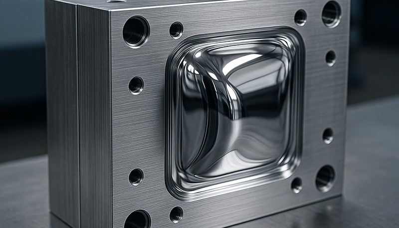
Core and cavity are the two mold-forming sides that create the final plastic part shape. The cavity usually forms the outside or visible surface, while the core usually forms internal surfaces, holes, bosses, ribs, undercuts, or the side that needs ejection support.
In a simple box-shaped part, the cavity may create the outside shell and cosmetic face, while the core creates the inside hollow space. In a more complex part, several inserts, lifters, sliders, or removable cores may work together. That is why real mold design is not just a male-half and female-half drawing.
In our experience, the best first review question is simple: which side controls the functional surface? If the cosmetic face, sealing face, clip feature, screw boss, or assembly datum is assigned to the wrong side, the mold may still make a part, but production quality becomes harder to control.
“Core and cavity decisions affect both part shape and production risk.”True
The mold split controls how plastic fills, where air escapes, how the part cools, where ejector force is applied, and which surface shows parting-line or flash marks.
“The cavity is always the fixed side and the core is always the moving side.”False
Many molds follow that convention, but complex tools can use inserts, sliders, lifters, unscrewing cores, and other mechanisms. Function and release strategy matter more than a simple label.
How do core and cavity shape a molded plastic part?
The core is used to form internal or raised features, while the cavity is used to form the outside contour and visible face. Molten plastic flows into the gap between these surfaces, cools against the steel, and becomes the final part geometry after the mold opens.
That gap is not just empty space. It defines wall thickness, rib depth, boss height, shutoff angle, gate access, venting, cooling distance, and ejection direction. A small mismatch between the core and cavity can create uneven walls, sink marks, flash, short shots, drag marks, or dimensional variation.
Wall thickness is the first thing to check. If the core sits too close to the cavity, the part may short shot or become weak. If the core sits too far away, the wall gets thick, cooling slows down, and sink marks appear near ribs or bosses. This is where early DFM earns its money.
| Design choice | Core-cavity impact | Risk if ignored |
|---|---|---|
| Wall thickness | Distance between core and cavity | Sink, short shot, long cycle |
| Parting line | Where mold halves meet | Flash, witness mark, mismatch |
| Ejection side | Where part stays after opening | Ejector marks or deformation |
| Cooling layout | Heat removal from both halves | Warping and uneven shrinkage |
Why do core and cavity decisions affect molding defects?
Core and cavity decisions are important because many molding defects start as tooling layout problems. Flash, burn marks, air traps, short shots, sink marks, warpage, drag marks, and parting-line mismatch often come from weak split decisions, poor venting, or unbalanced cooling.
For example, if a deep rib is formed by a thin core that cannot cool well, the nearby wall may shrink differently from the outside surface. If the cavity has a long flow path with no vent at the end, trapped air can create burn marks. These are not only processing problems.
A practical review should connect mold layout to defect prevention. Use a mould shrinkage checklist to ask which dimensional and cosmetic risks this core-cavity split could create, not just whether the 3D model can be machined.

The gate and runner plan also interacts with the core and cavity. If the gate enters near a cosmetic surface, the buyer may see a mark. If the flow path runs around a core feature, weld lines may meet at a weak section. Review the mold split together with injection molding production time assumptions, not after it.
How should engineers choose the parting line?
A parting line is the boundary where the core and cavity meet. It should be placed where it protects function, appearance, tool strength, and part release. A good parting line is not always hidden; it is placed where the mark is acceptable and controllable.
Start with the critical surfaces. Keep sealing faces, sliding faces, assembly datums, and high-cosmetic areas away from avoidable flash. Then review draft direction, undercuts, shutoffs, side actions, and ejection. A parting line that looks clean on screen may create a fragile shutoff in steel.
We recommend marking the part drawing with three zones: must-be-clean surfaces, acceptable mark surfaces, and hidden surfaces. That simple map helps the mold designer decide where the parting line, gate, ejector pins, sliders, and inserts can live without surprising the buyer at T1 samples.
“A visible parting line can still be a good design choice.”True
If the line sits on a noncritical surface and protects sealing, assembly, cooling, and mold strength, it may be better than hiding it in a fragile or expensive tool location.
“The best parting line is always the one that looks invisible in CAD.”False
A visually hidden line can create difficult shutoffs, weak steel, trapped air, or expensive side actions. Tooling practicality must be reviewed together with appearance.
What tolerances and mold steel details matter most?
Core and cavity tolerances are most critical where the molded part must seal, snap, slide, align, or hold a dimension after cooling. General surfaces can often accept wider tolerance, but shutoffs, ribs, bosses, clips, holes, and datum features need more careful steel and inspection planning.
Mold steel choice also matters. A soft insert may be fine for a prototype or low-volume trial, but it can wear quickly at shutoffs or texture areas. Hardened steel may cost more upfront, yet protect high-wear surfaces and keep dimensions stable during production.
The buyer should ask which dimensions are steel-safe, which are fixed after tooling, and which can be corrected after T1. If every dimension is treated as equally critical, the project becomes expensive. If no dimension is treated as critical, the assembly may fail.

In our Shanghai factory, our engineers use 20+ years of tooling experience, 47 injection molding machines from 90T to 1850T, in-house mold manufacturing, 100+ mold sets per month capacity, UG, SOLIDWORKS, MOLDFLOW, and CAD, plus ISO 9001, ISO 13485, ISO 14001, and ISO 45001 systems to review core-cavity split, steel-safe dimensions, cooling balance, and correction paths before mold build.
How should buyers review a core-cavity mold design before approval?
A good core-cavity review is a short engineering gate before tooling approval, not a long theoretical report. The buyer should confirm parting line, gate, runner, venting, cooling, ejection, steel-safe areas, critical dimensions, texture surfaces, and expected T1 correction path.
Ask the tooling team to show the mold open direction and explain where the part will stay when the tool opens. Ask where ejector pins push, where air exits, how inserts are retained, and which surface will show the parting line. These answers reveal whether the mold concept is mature.
A simple buyer checklist should separate must-control features from nice-to-have surfaces. Mark sealing areas, clip hooks, screw bosses, datum pads, visible texture zones, and assembly contact faces. Then ask the mold designer to explain how each feature is protected by the core-cavity split. This prevents a common problem: the tool looks acceptable in a general view, but the one feature that decides assembly fit sits across a weak shutoff or poor ejection zone.
For procurement discipline, compare mold suppliers with the same drawings, material, annual volume, tolerance list, surface standard, and assembly requirement. A structured supplier sourcing guide helps keep the review focused on evidence instead of only tooling price.
Before starting a mold, ask for a one-page DFM summary. It should list the planned core side, cavity side, parting line, gate, runner, vent, ejection, cooling, steel-safe correction points, and how T1 sample feedback will be handled. If the supplier cannot produce that summary, the mold design is probably not ready for purchase approval.

This does not need to slow the project. A strong supplier can usually explain the split, risks, and correction path quickly because the same questions affect machining, polishing, fitting, sampling, and production maintenance. The review only feels slow when the design team has not decided which surfaces truly matter.
Need a core-cavity DFM review? Send ZetarMold your 3D file, 2D drawing, resin, expected volume, and critical dimensions. Our team can review mold split, tooling risk, defect risk, and production assumptions before you commit to tooling.
Frequently Asked Questions
What is the difference between core and cavity in injection molding?
The core usually forms the internal or raised features of the molded part, while the cavity usually forms the outside shape and visible surface. In a simple plastic housing, the cavity may create the outside cosmetic shell and the core may create the inside hollow area. In real molds, the split can include inserts, sliders, lifters, and removable cores, so the function of each steel surface matters more than the label alone. A buyer should ask which side controls the critical surface, because that answer affects finish, ejection, flash risk, and correction options.
Is the core always on the moving side of the mold?
No. Many injection molds place the core on the moving side because the part often shrinks onto the core and needs ejection support there. However, complex mold layouts can change this assumption. Side actions, inserts, unscrewing features, or special cosmetic requirements may place forming features in different locations. The correct question is where the part will stay after opening and how it will be released without damage. That review also determines ejector pin marks, slider travel, mold maintenance access, and whether delicate features can survive repeated production cycles.
Why does core and cavity design cause flash?
Flash can happen when the core and cavity do not shut off cleanly, when clamp force is insufficient, when venting or pressure is poorly controlled, or when steel wears at the parting line. The design risk appears early if thin shutoffs, weak steel, long unsupported edges, or high-pressure flow paths sit near the split line. A DFM review should identify those areas before tooling is built. If the flash area touches a sealing face or visible cosmetic surface, the cost of late correction can be much higher than the cost of an early mold-split review.
How do I review core-cavity design before mold making?
Review the mold open direction, parting line, gate location, runner path, venting, ejection, cooling, critical dimensions, steel-safe areas, and cosmetic surfaces. Ask the supplier to show which features are formed by the core and which are formed by the cavity. Then connect those choices to expected defects, such as flash, sink marks, warpage, drag marks, trapped gas, and dimensional variation. A useful review also states which changes are easy after T1 and which changes would require major steel rework, so the buyer understands risk before approving tooling.
Can core and cavity changes be made after T1 samples?
Some core and cavity changes can be made after T1, but not all changes are equal. Steel-safe corrections, small dimension adjustments, vent changes, polishing, and some gate refinements may be manageable. Major parting-line relocation, new side actions, deep geometry changes, or cosmetic surface relocation can be expensive and slow. Buyers should ask which dimensions are adjustable before approving the mold design. The safest approach is to document critical dimensions, cosmetic limits, and expected sample correction methods before the mold build begins.
-
core: A core is a mold feature that forms an internal surface, hole, rib, boss, or negative geometry on a molded plastic part. ↩
-
cavity: A cavity is a mold space or surface that forms the outside shape, cosmetic face, or visible geometry of an injection molded part. ↩
-
parting line: A parting line is a visible or functional line where two mold halves meet and separate during molded part release. ↩


