 콘텐츠로 건너뛰기

구배 각도1 is the single most important geometric parameter you can get wrong in mold design — and it is also one of the easiest to fix if you catch it before steel is cut. A proper draft angle ensures that parts eject cleanly, without scratches, drag marks, or deformation, and it directly impacts cycle time, mold longevity, and part quality.
In production, draft angles typically range from 1° to 3° per side, but the exact value depends on the material, surface finish, part geometry, and texture requirements. A polished PE part might need only 0.5°, while a textured nylon component could require 3° or more.
This guide breaks down the factors that determine draft angle, provides material-specific reference values, and shares real production cases from our factory floor. Whether you are designing your first mold or troubleshooting ejection problems on an existing one, the principles below will help you get it right.
 사출 금형3ing draft angle diagram” class=”wp-image-53346 size-full” style=”max-width:100%;height:auto;” />
“Draft angles reduce ejection force in injection molding.”True
적절한 구배 각도는 부품과 금형 사이의 마찰을 최소화하여 사출을 원활하게 하고 손상을 방지합니다.
“All injection molded parts require a draft angle.”False
대부분의 부품은 드래프트 각도를 통해 이점을 얻을 수 있지만, 일부 저마찰 소재나 유연한 디자인에서는 드래프트가 전혀 없거나 최소화될 수 있습니다.
구배 각도의 정의와 중요성은 무엇인가요?
If you are comparing vendors or planning procurement, our injection molding sourcing guide covers RFQ prep, qualification, and commercial risk checks.
구배 각도는 사출 성형에서 필수적인 요소로, 원활한 부품 배출을 보장하고 금형 또는 최종 제품의 손상을 방지합니다.
구배 각도는 성형 부품을 금형에서 분리하고, 결함을 방지하며, 사출력을 줄이고, 금형 수명을 연장하기 위해 성형 부품에 약간의 테이퍼를 적용하는 각도입니다. 일반적으로 1~3도 범위입니다.
- Draft angles of 1–3° are standard for most injection-molded parts; specific values depend on material, texture, and geometry.
- Insufficient draft causes ejection defects (scratches, deformation), while excessive draft affects dimensional stability.
- Surface treatments (polishing, chrome plating) reduce friction and allow smaller draft angles.
- CAD simulation and FEA help optimize draft angles before tooling investment.
- Proper draft angle design extends mold life and reduces production costs.
드래프트 각도의 정의
구배 각도는 금형 캐비티 또는 코어와 금형 개방 방향 사이에 만들어진 각도, 즉 개방 방향에 대한 금형 벽의 경사입니다. 이 각도를 사용하면 금형 플라스틱 부품의 손상이나 변형에 대한 걱정 없이 쉽게 탈형할 수 있습니다.
드래프트 각도의 중요성
A well designed draft angle is capable of avoiding imperfections such as scratched and deformed products during the ejection process hence enhancing the surface finish of the product and incorporating sharp accuracies. Furthermore, getting a right draft angle can increase the mold’s life and lower the production expenses. If the draft angle chosen is too small, high ejection resistance is created which in turn creates surface scratches or deforms the plastic part; again if it is too large, the dimensional stability and mold life is affected. Hence, reasonable design about the draft angle contributes to promote the production quality and efficiency.
구배 각도 설계에 영향을 미치는 요인은 무엇인가요?
The right draft angle does not come from a single lookup table — it is the result of balancing several interacting variables. In our experience, the four factors below account for 90% of draft angle decisions.
Material type is usually the first factor engineers consider, but surface finish, part structure, mold precision, and process parameters all play important roles. Below we walk through each one with specific recommendations.
플라스틱 재질
Different plastics shrink and grip the mold differently. The table below summarizes the recommended draft angle ranges for common injection molding materials:
| 재료 | Recommended Draft Angle | 참고 |
|---|---|---|
| 폴리에틸렌(PE) | 0.5° to 1.5° | Low shrinkage, slippery — minimal draft needed |
| 폴리프로필렌(PP) | 1° to 2° | Semi-crystalline, moderate shrinkage |
| 폴리스티렌(PS) | 0.5° to 1.5° | Amorphous, low shrinkage, rigid |
| ABS | 1° to 2° | Amorphous, good release characteristics |
| 소비재용 다양한 색상의 플라스틱 성형 부품 | 2° to 3° | High shrinkage, strong adhesion to mold |
제품 구조
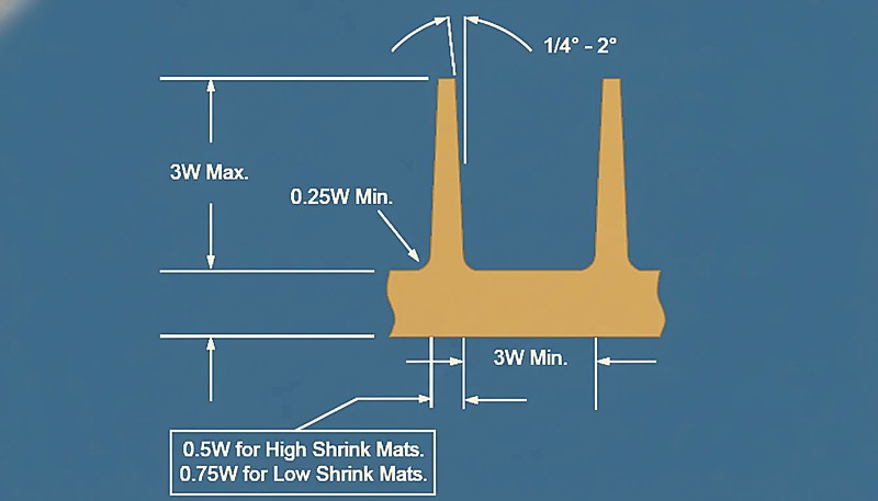
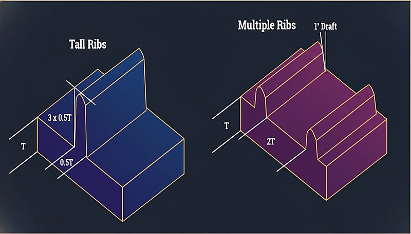
구배 각도는 제품의 모양과 구조에도 영향을 받습니다. 모양이 복잡하고 벽 두께가 고르지 않은 제품은 구배 각도가 커야 탈형이 용이하다는 점에 유의해야 합니다. 예를 들어 복잡한 기하학적 특징이나 내부 리브와 같은 미세한 특징이 있는 부품은 이형 중에 많은 저항이 발생하므로 구배 각도를 늘려야 합니다.
금형 가공 정밀도
The higher the mold processing accuracy and the smoother the surface, the smaller the required draft angle. On the contrary, if the mold surface is rough, the draft angle needs to be increased to reduce the ejection force. Lubrication, high-precision processing, and surface treatments such as polishing and chrome plating can help reduce friction and improve ejection efficiency.
사출 공정 파라미터
Other important process parameters such as injection pressure, temperature and speed also affect the draft angle design. Higher injection pressure and temperature have effect in terms of increasing the shrinkage rate of plastic part and may demand a bigger draft angle. Varying process conditions impact the material’s behaviour in terms of its flow and solidification, meaning that these elements must be addressed in the design process.
드래프트 앵글 디자인의 기본 원칙은 무엇인가요?
In our Shanghai factory, we run 47 injection molding machines (90T to 1850T) with an in-house mold manufacturing facility. Draft angle issues are one of the most common tooling problems we encounter — and getting it right from the design stage saves weeks of rework and thousands in tooling costs.
The principles behind good draft angle design are straightforward, but they require judgment. Here are the guidelines our tooling engineers follow when planning a new mold.
The core principle is simple: add enough taper to let the part release without excessive force, but not so much that it compromises dimensions or wastes material. The guidelines below help you find that balance.
플라스틱 유형에 따른 구배 각도 선택
Rather than repeating raw numbers, consider the underlying logic: low-shrinkage, slippery materials like PE and PP need less draft because they release easily. High-shrinkage, sticky materials like nylon and glass-filled compounds need more. Here is a practical decision guide:
제품 벽 두께 및 모양 고려
벽이 두꺼운 제품의 수축이 클수록 필요한 통풍각이 커집니다. 내부 나사산이나 홈과 같이 복잡한 모양을 가진 제품도 구배 각도를 늘려야 합니다.
매끄러운 금형 표면 보장
금형 표면 마감을 향상시키면 이형 저항을 최소화하는 데 확실히 도움이 되며, 이는 성형 공정에서 필요한 구배 각도를 최소화할 수 있음을 의미합니다. 일반적으로 사용되는 방법은 폴리싱과 크롬 도금입니다.
합리적인 사출 공정 파라미터 보장
구배 각도를 설계할 때 사출 공정의 필수 파라미터를 고려해야 사출 공정에 맞는 금형 설계를 보장할 수 있습니다. 예를 들어 사출 압력과 온도를 낮추면 설계된 플라스틱 부품의 수축률이 감소하고 결과적으로 구배 각도 설계가 향상됩니다.
구배각과 금형 수명의 관계는 무엇인가요?
The relationship between draft angle and mold life is defined by the function, constraints, and tradeoffs explained in this section. Every ejection cycle puts stress on the mold surface. Without adequate draft, the friction between the cooling plastic and the steel cavity accelerates wear, shortens tool life, and increases maintenance costs.
구배 각도는 부품 배출 시 마찰을 줄여 금형 응력을 최소화하고 고착과 손상을 방지합니다. 적절한 각도는 유지보수 필요성을 줄이고 조기 금형 고장을 방지하여 금형 수명을 연장하고 효율성을 개선하며 생산 비용을 절감합니다.
적절한 구배 각도는 플라스틱 부품의 품질에 영향을 미칠 뿐만 아니라 금형의 수명에도 직접적으로 작용합니다. 구배 각도가 너무 작으면 플라스틱 부품과 금형 사이에 마찰이 많이 발생하여 표면이 마모되고, 구배 각도가 너무 크면 제품의 치수에 영향을 미칩니다. 따라서 구배에 필요한 각도 설계는 금형에 사용되는 재료의 종류, 필요한 표면 처리의 종류 및 금형 수명을 연장하고 효율성을 향상시키는 기타 요소를 특징으로 합니다.
“Larger draft angles extend mold life by reducing friction.”True
드래프트 각도가 증가하면 부품이 더 쉽게 방출되어 기계적 응력이 감소하고 금형 내구성이 연장됩니다.
“Draft angles are unnecessary for injection molding.”False
구배각이 없으면 부품이 금형에 달라붙어 결함이 발생하고 마모가 증가하며 유지보수가 빈번해져 궁극적으로 금형 수명이 단축될 수 있습니다.
구배 각도를 최적화하는 방법에는 어떤 것이 있나요?
The methods for optimizing draft angle are the main categories or options explained in this section. Modern draft angle optimization relies on a combination of CAD analysis, simulation, and production verification. The best results come from using all three methods together rather than relying on any single approach.
구배 각도 최적화는 재질, 두께, 형상을 고려하여 각도를 조정합니다(일반적으로 1~3도). 질감이 있는 표면에는 더 많은 각도가 필요합니다. 적절한 각도는 금형 이형을 개선하고 마모를 줄이며 내구성을 높입니다.
컴퓨터 지원 설계(CAD)
CAD 소프트웨어는 사출 금형의 구배 각도를 정확하게 계산하고 시뮬레이션할 수 있습니다. 이상적인 각도를 미리 계산하고 시뮬레이션하면 맹목적인 설계의 가능성을 줄여 설계 효율성을 높일 수 있습니다. 예를 들어 구배 분석에 소프트웨어를 사용하면 문제가 있을 수 있는 부분을 찾아 수정할 수 있습니다.
수치 시뮬레이션
실험적 검증
In the real production process, it is necessary to compare the effects of different draft angles by experimental confirmation in order to gradually optimize the angle. In the course of experiments, measuring ejection force and observing product surface quality can evaluate the rationality of the draft angle.
종합적인 고려 사항
구배 각도 설계 시 재료의 특성, 제품의 구조, 금형 가공 및 사출 공정 파라미터를 고려하여 설계된 구배 각도가 제품의 품질과 금형의 내구성을 유지할 수 있도록 해야 합니다.
사출 금형의 구배 각도에 대한 일반적인 문제와 해결책은 무엇입니까?
The common problems and solutions for draft angle of injection molds are the main categories or options explained in this section. Even experienced tooling engineers encounter draft angle problems during production trials. The four issues below are the most common — and fortunately, each has a straightforward fix if you catch it early.
성형 시 균형 잡힌 구배 각도는 부품을 쉽게 방출하고, 왜곡을 방지하며, 이형 난이도를 최소화하고, 금형 마모를 줄여 원활한 생산과 불량 감소를 촉진합니다.
어려운 배출
생산 중 배출이 어려운 경우 구배 각도가 작을 수 있으므로 구배 각도를 측정해야 합니다. 분리를 최적화하려면 구배 각도를 높이고 금형 표면을 연마하거나 크롬 도금하여 마찰을 줄여야 합니다.
제품 변형
Even experienced tooling engineers encounter draft angle problems during production trials. The four issues below are the most common — and fortunately, each has a straightforward fix if you catch it early.
표면 스크래치
Common causes of a surface scratch include lack of draft angle or a rough surface of the mold. This problem can be solved by raising the angle of the draft and increasing the surface quality of the mold.
과도한 배출력
높은 토출력은 작은 구배 각도 또는 사출 공정 변수의 부적절한 선택으로 인해 발생할 수 있습니다. 부품의 구배 각도를 수정하고 사출 압력 및 온도를 낮추는 등 사출 공정 변수를 개선하면 토출력을 최소화할 수 있습니다.
“Incorrect draft angles cause ejection problems.”True
구배 각도가 부적절하면 부품을 배출하기 어려워져 결함이 발생하고 금형의 마모가 증가할 수 있습니다.
“Excessive draft angles are always better.”False
과도한 구배 각도는 배출을 용이하게 할 수 있지만, 부품의 구조적 약점과 불필요한 재료 낭비를 초래할 수 있습니다.
사출 금형의 구배각의 실제 적용 사례는 무엇입니까?
The practical application cases of draft angle of injection molds are the main categories or options explained in this section. The practical cases below show how draft angle adjustments solved real production problems across different materials and part geometries. Each case includes the initial design, the problem encountered, and the corrective action taken.
사례 1: 폴리프로필렌 플라스틱 부품의 구배 각도 설계
한 회사에서 벽 두께가 2mm인 폴리프로필렌 캡을 설계했습니다. 폴리프로필렌의 권장 구배 각도는 약 1.5°입니다. 생산 초기에는 제품을 배출할 때 가장자리 표면에 스크래치가 있는 것을 발견했습니다. 구배 각도를 2°로 높인 후 스크래치 문제가 해결되고 제품 품질이 향상되었습니다.
사례 2: 나일론 플라스틱 부품의 구배 각도 설계
An electronic product housing made from nylon (PA66) required a draft angle that could accommodate both the external cosmetic surface and internal rib structures. The initial design used a uniform 1.5° draft, but during sampling, the internal ribs showed drag marks. The engineering team increased the core-side draft to 2.5° while keeping the cavity side at 1.5°. This differential draft approach eliminated the drag marks and maintained the external dimensional tolerance within specification.
사례 3: 복잡한 형상의 플라스틱 부품을 위한 구배 각도 설계
특정 가전 제품의 쉘은 복잡한 구조, 많은 홈과 리브가있는 ABS 재질로 만들어집니다. 구배 각도를 계산할 때 초기 구배 각도는 첫 번째 매개 변수로 1.5°로 설정됩니다. 시험 생산 중에 일부 홈이 배출되는 데 어려움이 있었습니다. 그루브의 구배 각도를 2.5°로 높이고 금형 표면을 크롬 도금함으로써 배출 문제를 해결하고 완벽한 제품을 생산할 수 있었습니다.
사례 4: 소형 전자 제품 하우징
A company designed housing for a small electronic product using ABS material with an initial draft angle of 1°. During trial production, ejection difficulties and surface scratches were observed, particularly around rib features. The draft angle was increased to 2°, and the mold surface was polished to an SPI A-2 finish. After these changes, ejection force dropped by approximately 40%, and the surface quality met the cosmetic specification without secondary finishing.
사례 5: 자동차 부품
한 자동차 부품 제조업체는 초기 구배 각도가 2.5°인 고정밀 나일론 바디 사출 성형 부품을 생산해야 합니다. 소량 배치 테스트 결과 이형이 어렵고 금형 표면 마모율이 높은 것으로 나타났습니다. 구배 각도를 3.5°로 높이고 금형 표면을 크롬 도금하여 이형 문제를 해결하고 금형 수명을 연장했습니다.
사례 6: 가정용 제품 플라스틱 부품
한 생필품 공장에서 벽 두께가 3mm인 폴리프로필렌 플라스틱 용기를 생산합니다. 초기 구배 각도는 1.5°입니다. 시제품 생산 중 이형 시 제품이 변형되기 쉽습니다. 구배 각도가 2.5°로 증가하고 사출 공정 매개 변수가 최적화되고 이형이 원활하며 제품 품질이 향상됩니다.
“Draft angles improve part ejection and reduce molding defects.”True
구배 각도는 마찰을 줄여 이형 공정을 간소화하여 부품 손상과 금형 마모를 최소화합니다.
“A higher draft angle always leads to better results.”False
구배 각도가 클수록 부품을 쉽게 제거할 수 있지만, 각도가 너무 가파르면 부품의 구조적 무결성이 손상되고 금형 복잡성이 증가할 수 있습니다.
사출 금형의 구배 각도의 향후 발전 방향은 무엇입니까?
The future development direction of draft angle of injection molds is defined by the function, constraints, and tradeoffs explained in this section. Looking ahead, draft angle design is evolving alongside advances in simulation software, additive manufacturing for tooling, and new polymer formulations. Three trends are shaping the next generation of mold design:
미래의 사출 금형 구배 각도는 파팅 라인 가시성 감소, 금형 이형 향상, 폐기물 최소화에 중점을 두어 제품 품질 향상과 생산 속도 향상을 위한 고급 설계를 활용합니다.
As 사출 성형 technology enhances draft angle design also enhances and adopts the best method. As the computer and numerical simulation technology progresses, the draft angle design will be even more accurate and faster created. At the same time, application of the new materials and processes will also introduce the new challenges and possibilities for the draft angle design. For example, the innovation of 3D printing technology provides new opportunities to design and create the molds of complex shapes.
“Draft angles help reduce mold ejection issues.”True
구배 각도는 사출 시 마찰을 줄여 성형 부품의 손상을 방지하고 사이클 시간을 개선합니다.
“Increasing draft angles always improves mold efficiency.”False
구배 각도는 사출을 개선하지만, 지나치게 큰 각도는 성형 부품의 강도를 감소시키고 디자인 미학에 영향을 줄 수 있습니다.
What Are the Key Takeaways on Draft Angle Design for Injection Molds?
Draft angle is one of the most critical yet commonly overlooked parameters in 사출 금형 설계. Getting it right the first time saves tooling rework, prevents production defects, and extends mold life — we see this play out daily on our production floor.
The key to a successful draft angle strategy is balancing material behavior, surface finish requirements, and part geometry. Standard ranges like 1–2° for PE/PP and 2–3° for nylon give you a starting point, but every part is different. That is why CAD draft analysis combined with production trials remains the gold standard for optimization. If you are unsure where to start, most tooling engineers recommend beginning with 1.5° per side for polished surfaces and adding 1° for every 0.25 mm of texture depth.
| Decision Area | What to Verify |
|---|---|
| 재료 선택 | Match draft to resin shrinkage: low-shrinkage (PE/PP) 0.5-2°, high-shrinkage (nylon/GF) 2-3° |
| 표면 마감 | Polished surfaces need less draft; add 1° per 0.25 mm texture depth |
| 부품 지오메트리 | 딥 드로우, 리브, 언더컷은 모두 필요한 드래프트 각도를 증가시킵니다 |
| 공정 윈도우 | 높은 사출 압력/온도는 수축률을 증가시킵니다 — 이에 따라 계획하세요 |
Need a Quote for Your Injection Molding Project?
Get competitive pricing, DFM feedback, and production timeline from ZetarMold’s engineering team.
Request a Free Quote →
Frequently Asked Questions About Draft Angle in Injection Molding
사출 성형의 표준 드래프트 각도는 무엇인가요?
대부분의 사출 성형 부품에 대한 표준 드래프트 각도는 측면당 1~3도 범위입니다. PE나 PP와 같은 저수축 재료로 연마된 금형 표면의 경우 0.5~1.5도면 충분할 수 있습니다. 텍스처 표면은 일반적으로 텍스처 깊이 0.25mm마다 추가로 1도의 드래프트가 필요합니다. 실제로는 측면당 1.5도로 시작하여 재료 시험을 기반으로 조정하는 것이 신뢰할 수 있는 접근법입니다. 드로우 깊이가 100mm를 초과하는 딥 드로우 부품의 경우, 대부분의 엔지니어는 이젝션 시 더 큰 표면 접촉 면적을 고려하여 표준 드래프트를 2~3도로 증가시킵니다.
드래프트 각도가 부품 치수에 영향을 미치나요?
예, 드래프트 각도는 부품의 단면 치수를 위에서 아래로 직접 변경합니다. 측면당 2도 드래프트가 있는 50mm 높이의 벽의 경우, 벽 상단과 하단의 차이는 측면당 약 1.75mm로, 드래프트 각도의 탄젠트 값에 벽 높이를 곱한 값의 2배로 계산됩니다. 엔지니어는 특히 다른 부품과 결합하거나 조립되는 부품의 경우 공차 적산에서 이 테이퍼를 고려해야 합니다. 정밀 애플리케이션에서는 드래프트로 인한 치수 변동이 사용 가능한 공차 대역의 상당 부분을 차지할 수 있으므로 부품 설계의 초기 단계부터 계획되어야 합니다.
드래프트 없이 사출 성형할 수 있나요?
기술적으로는 가능하지만, 생산에는 거의 권장되지 않습니다. 드래프트 없이는 이젝션 힘이 급격히 증가하여 표면 긁힘, 부품 변형 및 금형 마모 가속화를 유발합니다. HDPE나 고무 같은 TPE와 같은 일부 유연한 소재는 이젝션 중 재료가 늘어나기 때문에 얕은 형상에서 거의 제로 드래프트를 허용할 수 있지만, 그런 경우에도 신뢰할 수 있는 생산을 위해 측면당 최소 0.5도가 표준 관행입니다. ABS나 폴리카보네이트와 같은 경질 소재의 경우, 수직 표면에서 제로 드래프트 성형을 시도하면 거의 항상 드래그 마크와 불량률 증가가 발생하여 인지된 설계 이점을 상쇄합니다.
표면 질감이 드래프트 각도 요구 사항에 어떤 영향을 미치나요?
텍스처 처리된 금형 표면은 플라스틱과 금형 벽 사이에 기계적 인터록을 생성하여 이젝션 저항을 크게 증가시킵니다. 일반적인 경험 법칙은 텍스처 깊이 0.25mm마다 1도의 드래프트를 추가하는 것입니다. 예를 들어, 일반적으로 1도의 드래프트가 필요한 부품에 0.5mm 깊이의 미세한 가죽 무늬 텍스처가 적용된 경우, 드래그 자국 없이 깨끗하게 이젝션하려면 측면당 최소 3도의 드래프트가 필요합니다. 이는 금형 설계 검토에서 가장 자주 과소평가되는 요소 중 하나이며, 설계 단계에서 텍스처 깊이를 고려하지 않으면 초기 샘플링 후 비용이 많이 드는 금형 재작업으로 이어지는 경우가 많습니다.
드래프트 각도가 너무 크면 어떻게 되나요?
과도한 드래프트 각도는 재료를 낭비하고, 부품 벽을 고르지 않게 두껍게 만들며, 다중 부품 제품에서 조립 적합성 문제를 일으킬 수 있습니다. 또한 사용 가능한 캐비티 부피를 줄이고, 증가된 테이퍼를 수용하기 위해 결합 피처의 재설계가 필요할 수 있습니다. 극단적인 경우, 과대한 드래프트 각도는 벽 두께 분포가 고르지 않아 냉각 중 부품의 뒤틀림을 유발할 수 있습니다. 대부분의 엔지니어는 표준 부품의 경우 측면당 5도 이상을 불필요한 것으로 간주하며, 더 큰 각도는 깊은 드로우 또는 강하게 텍스처가 적용된 애플리케이션에만 사용합니다. 핵심은 부품 기능적 요구 사항을 저해하지 않으면서 신뢰할 수 있는 이젝션을 허용하는 최소 드래프트를 찾는 것입니다.
코어 측과 캐비티 측의 드래프트 각도는 동일한가요?
항상 그런 것은 아닙니다. 부품 내부를 형성하는 코어 측은 냉각 중에 플라스틱이 코어 위로 수축하여 더 큰 마찰과 더 높은 이젝션 힘을 생성하기 때문에 캐비티 측보다 더 많은 드래프트가 필요한 경우가 많습니다. 일반적인 지침은 캐비티 측에 비해 코어 측에 0.5~1도 더 많은 드래프트를 적용하는 것입니다. 이 차이는 딥 드로우 부품이나 나일론 및 유리 충전 화합물과 같은 고수축률 재료의 경우 특히 중요해집니다. 벽 두께가 충분한 얕은 부품의 경우 코어-캐비티 드래프트 차이는 무시할 수 있을 수 있지만, 항상 금형 설계 검토 중에 확인해야 합니다. 자세한 내용은 complete guide to injection molding.


