 콘텐츠로 건너뛰기

In this guide, I’ll walk through what draft angle is, how to calculate it for different materials and surface finishes, and the specific numbers we use on the shop floor after 20+ years of making injection molds. No theory without practice — just the rules that actually work.
- Draft angle is the taper on vertical mold surfaces that lets parts eject cleanly
- Most parts need 1–3° minimum draft; textured surfaces need 1–1.5° extra per 0.001″ texture depth
- Harder plastics (PC, POM) and glossy finishes require more draft than soft or matte ones
- Missing or insufficient draft causes sticking, scratches, and cycle time increases
- Always apply draft in the direction of mold opening — and verify with your molder before tooling
What Is a Draft Angle in Injection Molding?
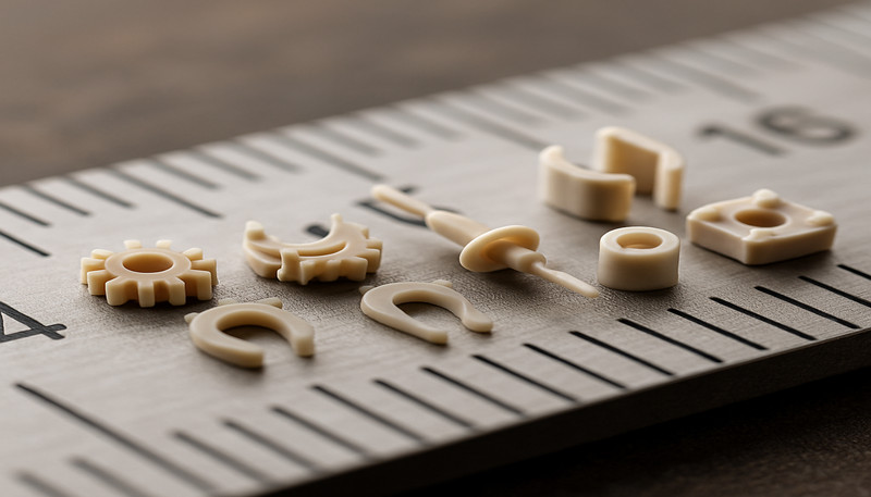
A draft angle in injection molding is defined by the function, constraints, and tradeoffs explained in this section. A draft angle is the deliberate taper you build into every vertical face of a part so it can be ejected from the injection molding tool without fighting friction. Think of it like the slight slope on the inside of an ice cube tray — without that slope, you’d never get the ice out in one piece.
In technical terms, draft angle is measured in degrees from the vertical axis of the mold opening direction. If a wall is perfectly perpendicular to the parting line (0° draft), the part creates a vacuum seal against the steel as it cools and shrinks. That seal is what makes ejection2 brutal — or impossible. Adding even 0.5° of taper breaks that seal and lets air in behind the part during ejection.
Here’s a number that surprises a lot of designers: the friction force between a cooling plastic part and a polished steel core can exceed 500 N per square centimeter of contact area. On a part with a 50 mm tall cylindrical wall, that’s potentially thousands of newtons of holding force working against your ejector pins. Draft angle is what keeps that force manageable.
In our shop, we’ve seen parts come in for rework where the original designer specified 0° draft on a 40 mm deep bore. The result? Every 20th part stuck and had to be pried out manually — on a high-speed production run of 100,000 parts. The fix was a mold modification costing $3,500 and two weeks of lost production. A 1° draft from the start would have cost exactly nothing.
“Adding just 0.5° of draft angle can break the vacuum seal between a plastic part and the mold core, making ejection possible.”True
Even a tiny taper allows air to flow behind the part during ejection, dramatically reducing the force needed to separate the part from the steel. Without any draft, the vacuum effect can make ejection physically impossible without damaging the part.
“Draft angle is only necessary on the cavity side of the mold, not the core side.”False
The opposite is true: the core side is where draft matters most. As plastic shrinks during cooling, it grips the core tighter. The cavity side actually benefits from natural 수축3 pulling the part away from the steel. This is why core-side draft specifications are always more critical in mold design.
Why Do Injection Molded Parts Need Draft Angles?
이 섹션은 사출 성형 부품이 드래프트 각도가 필요하며 이가 비용, 품질, 시기 또는 조달 리스크에 미치는 영향에 관한 것입니다. 부품에 드래프트 각도가 필요한 이유는 각도 없이 플라스틱이 냉각 중 금형 코어에 단단히 수축되어 마찰이 발생하여 이젝션을 불가능하게 하거나 최소한 손상을 일으키기 때문입니다. 드래프트 각도(수직 표면의 테이퍼)는 진공 밀봉을 깨고 접촉 마찰을 줄여 매 사이클마다 깨끗하고 안정적인 부품 제거를 가능하게 합니다. 피처가 높고 재료가 강할수록 드래프트 각도는 더욱 중요해집니다.
During cooling, thermoplastic shrinks toward the center of its mass. On external features (cavity side), this shrinkage pulls the plastic away from the steel — that’s helpful. But on internal features (core side), shrinkage pulls the plastic tighter onto the steel. The taller and straighter the core surface, the more contact area, the more friction, the harder the ejection. Draft angle progressively reduces that contact area from bottom to top.
적절한 드래프트 각도 없이는 생산 전반에 걸쳐 여러 문제가 연쇄적으로 발생할 것입니다: 수동 제거가 필요한 부품 고착, 매 사이클마다 발생하는 표면 긁힘 및 끌림 자국, 조기 핀 파손으로 이어지는 이젝터 핀 응력 증가, 뒤틀림이나 균열을 유발하는 불균일한 이젝션, 그리고 이젝션 단계를 안전하게 가속할 수 없어 사출 성형 생산 시간이 길어집니다.
I’ve also seen cases where zero-draft parts would eject fine on the first 50 shots of a new, polished tool — but started sticking after 5,000 shots as the mold surface developed microscopic wear. Draft isn’t just about making it work on day one; it’s about making it work reliably for the life of the tool.
There’s a secondary benefit that’s often overlooked: draft angle improves airflow and coolant flow inside the mold. Tapered surfaces create a natural vent path that helps trapped air and gas escape during filling. This reduces burn marks, short shots, and the need for complex venting schemes — especially on deep-ribbed parts.
What Factors Affect the Required Draft Angle?
이 섹션은 필요한 드래프트 각도에 영향을 미치는 요인과 그 요인이 비용, 품질, 시기 또는 조달 리스크에 미치는 영향에 관한 것입니다. 필요한 드래프트 각도를 결정하는 다섯 가지 주요 요인은 다음과 같습니다: 재료 강성, 표면 마감, 부품 형상(피처 깊이), 벽 두께, 생산량. 강성 플라스틱, 텍스처 표면, 깊은 피처, 대량 생산은 모두 필요한 드래프트 각도를 높입니다 — 까다로운 조합의 경우 일반적으로 1.5–3°, 쉬운 경우 0.5–1°입니다.
Material stiffness: Rigid materials like polycarbonate (PC), POM (acetal), and glass-filled nylons resist deformation during ejection. They don’t “give” as they slide off the core, so they need more draft — typically 1.5–3°. Softer materials like TPU, PE, and PP can tolerate less draft (0.5–1°) because they flex slightly during ejection and release more easily.
Surface finish: This is the factor that catches people off guard. A polished (A1 or A2 SPI finish) mold surface has low friction, so 0.5–1° draft might suffice. But a textured surface (SPI B, C, or D finish, or EDM) acts like microscopic teeth gripping the plastic. For every 0.001″ (0.025 mm) of texture depth, you need to add 1–1.5° of additional draft.
“A deep leather-grain texture at 0.004″ depth may require 4–6° of additional draft angle on top of the base material draft.”True
Texture depth is one of the most underestimated factors in draft angle specification. Each 0.001″ of texture depth adds roughly 1–1.5° of required draft. A deep leather grain at 0.004″ is actually a common specification that catches many designers off guard, especially when the texture is applied after the initial mold design is complete.
“Textured mold surfaces require the same draft angle as polished surfaces because the texture does not affect friction.”False
Textured surfaces dramatically increase friction during ejection. The microscopic peaks and valleys of the texture interlock with the plastic surface, creating mechanical resistance that polished steel simply does not have. This is why textured molds always need significantly more draft — often 3–6° more than their polished equivalents.
Part geometry: Deep draws, tall ribs, and long cores all amplify friction. A 10 mm deep pocket with 1° draft works fine; a 100 mm deep pocket with 1° draft is a recipe for sticking because the contact area is 10× larger. As a rule of thumb, for features deeper than 50 mm, increase draft by at least 0.5° per additional 25 mm of depth.
Wall thickness: Thicker walls shrink more, which increases the gripping force on cores. A 4 mm wall section will need more draft than a 1.5 mm section for the same geometry and material.
Production volume: For low-volume prototype 사출 금형 설계 and tooling (under 1,000 shots), you can get away with less draft because the tool stays pristine. For production tooling running 100K+ cycles, generous draft is essential — the mold surface will degrade over time, and what works on shot #1 may stick on shot #50,000.
How Do You Calculate the Correct Draft Angle?
There are two practical approaches: rule-of-thumb tables and CAD-based analysis. For most parts, the table-based method is sufficient. For high-precision or complex parts, CAD simulation catches problems the tables miss.

기본 공식: 주어진 피처 깊이(H)와 상단에서 원하는 간격(C)에 대해, 드래프트 각도 θ = arctan(C / H)입니다. 실제로 대부분의 엔지니어들은 이를 계산하지 않습니다 — 재료별 최소값을 참조하고 안전 여유를 추가합니다.
Rule of thumb for smooth surfaces:
– Small parts (150 mm feature depth): ≥2–3°
– All surfaces: minimum 0.5° even for low-friction materials
텍스처 조정: 텍스처 표면의 경우, 텍스처 깊이 0.001″(0.025 mm)당 1–1.5°를 추가하세요. 귀하의 사출 성형 공급업체 should provide the exact depth specification — always confirm with them before finalizing draft.
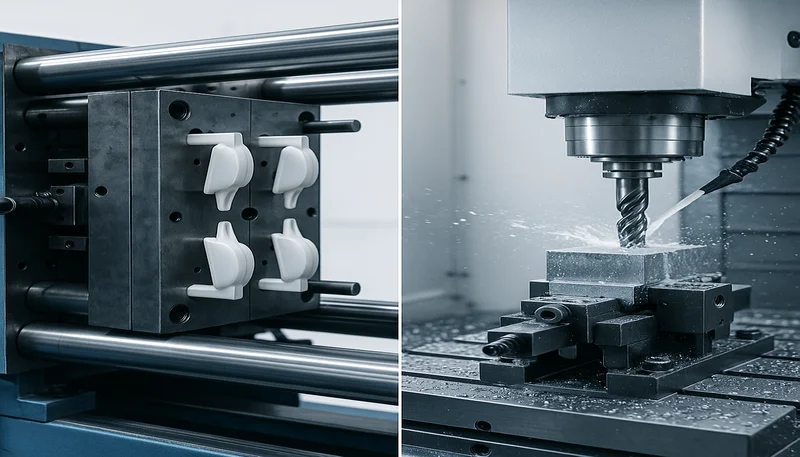
CAD-based analysis: Modern mold flow simulation tools (Moldflow, Moldex3D) can predict ejection forces and identify areas where draft is insufficient. We run these simulations on complex parts to catch draft-related issues before steel is cut. It’s far cheaper to fix a CAD model than to re-cut a cavity.
One practical tip we use on the shop floor: when in doubt, add draft. It’s almost never wrong to have more draft than the minimum — the only cases where excessive draft causes problems are precision fits and snap-fit features where the taper changes the geometry. For those features, you specify draft direction (toward or away from the functional surface) and verify with tolerances.
What Draft Angle Standards Should You Follow by Material?
For smooth mold surfaces, most engineering plastics (ABS, PA66, PC) need 1–2° of draft, while softer materials like PP and TPU can get by with 0.5–1°. High-temperature or glass-filled materials like PEEK and GF-PA66 require 1.5–3°. For every step of texture depth (0.001″), add another 1–1.5° on top of these base values. The table below breaks it down by material.
| 재료 | Min. Draft (°) | Recommended (°) | 참고 |
|---|---|---|---|
| ABS | 0.5 | 1.0–1.5 | Low shrinkage; forgiving |
| PC | 0.5 | 1.0–2.0 | Rigid; higher friction |
| PA66 | 0.5 | 1.0–1.5 | Glass-filled needs more |
| PP | 0.25 | 0.5–1.0 | Soft; easy release |
| POM | 0.5 | 1.0–2.0 | Rigid but slippery |
| TPU | 0.25 | 0.5–1.0 | Elastomeric; self-releasing |
| PEEK | 0.5 | 1.5–3.0 | High-temp; generous draft needed |
| PMMA | 0.5 | 1.0–2.0 | Brittle; needs smooth ejection |
Important caveat: these are for smooth (SPI A-2 or better) mold surfaces. For every step down in surface finish (polished → fine matte → coarse matte → textured), add 0.5–1.5° to the recommended draft. For EDM surfaces, add 1–2° minimum.
Glass-filled grades deserve special mention. When you move from unfilled PA66 to 30% glass-filled PA66, the part becomes significantly more rigid and abrasive. The filler also increases the surface roughness of the molded part, which increases friction during ejection. Our rule: add 0.5–1° extra for any glass-filled or mineral-filled grade.
What Are Common Draft Angle Mistakes?
Common draft angle mistakes are the main categories or options explained in this section. After two decades of reviewing mold designs, I see the same draft angle mistakes over and over. Here are the ones that cost the most money and time.

Mistake 1: Specifying 0° draft on cosmetic surfaces. Some designers think draft will be visible on show surfaces and therefore specify zero. The reality: 0.5° is virtually invisible on most parts, and 1° is imperceptible on anything larger than a medical micro-mold. Meanwhile, 0° draft on a polished cosmetic surface means drag marks on every single part — which is a lot more visible than 1° of taper.
“A 1° draft angle is virtually invisible on most injection molded parts, yet it prevents costly ejection problems.”True
Many designers avoid draft on cosmetic surfaces, fearing visible taper. In reality, 0.5–1° of draft is imperceptible on parts larger than a few centimeters. The drag marks caused by zero-draft ejection are far more visible and damaging to part appearance.
“If a part ejects fine during initial sampling, the draft angle is sufficient for production.”False
Initial sampling uses a fresh, polished mold surface. After thousands of cycles, microscopic wear increases friction on marginal-draft features. What ejects cleanly on shot #10 may stick consistently by shot #5,000. Production reliability requires more draft than sampling suggests.
Mistake 2: Ignoring draft on ribs and bosses. Everyone remembers the outside walls. But internal ribs and bosses have the tightest ejection clearances and the smallest ejector pin contact area. These features need at least 0.5° per side — and many designers leave them at 0° because they’re “small.” A stuck rib is just as production-stopping as a stuck wall.
Mistake 3: Not accounting for texture depth. This one happens when the texture specification is added after the mold design is finalized. The designer uses smooth-surface draft values, the texture gets applied later, and suddenly every part sticks. Always confirm the texture depth before finalizing draft.
Mistake 4: Draft in the wrong direction. If you apply draft that tapers the part smaller at the parting line instead of larger, you’ve created an undercut — the part now locks into the mold instead of releasing from it. This is a CAD error, but it gets through to tooling more often than you’d think, especially on complex multi-core parts.
Mistake 5: Insufficient draft on deep pockets. A 2° draft on a 5 mm deep pocket is fine. The same 2° on a 100 mm deep pocket may not be enough — the friction force scales with surface area, and a 100 mm deep wall has a lot of surface area. For deep features, increase draft progressively or use stepped drafts.
The common thread in all these mistakes: they’re all cheap to fix in CAD and expensive to fix in steel. Catching a draft problem on screen takes 30 minutes. Fixing it in a hardened steel cavity takes two weeks and thousands of dollars. That’s why a thorough draft review should be part of every mold design sign-off before machining starts.
With 20+ years of experience, 8 senior engineers, 47 injection molding machines from 90T to 1850T, and in-house mold manufacturing capacity for 100+ mold sets per month, ZetarMold catches draft-related DFM risks before steel is cut.
자주 묻는 질문
What is the minimum draft angle for injection molding?
The absolute minimum is 0.25° for very soft, flexible materials like TPU or LDPE with a polished mold surface. For most engineering plastics (ABS, PA66, PC) on a smooth surface, the practical minimum is 0.5–1°. Anything below 0.5° is risky for production tooling and should only be used when the part geometry absolutely cannot accommodate more draft. In production environments, most molders recommend at least 1° as a comfortable starting point for most materials to ensure reliable ejection over the full life of the tool.
Can you injection mold parts with zero draft angle?
Technically yes, but it requires special measures: generous use of mold release agents, very slow ejection speeds, and acceptance of higher scrap rates. Zero-draft parts typically need stripper plates instead of ejector pins, and even then, you’ll see surface drag marks on every part. For any volume above prototyping, zero draft is a false economy that leads to inconsistent quality and costly mold rework. Most experienced molders will flag zero-draft features as a DFM risk and recommend at least minimal taper.
How does surface finish affect the required draft angle?
Surface finish is one of the most impactful factors in draft angle specification. A polished (SPI A-1) surface needs only 0.5–1° draft for most materials because the smooth steel has low friction. A standard EDM finish (SPI C-1) needs 1.5–2° extra because the spark-eroded texture grips the plastic mechanically. Textured surfaces need an additional 1–1.5° per 0.001″ of texture depth. Always get the finish specification confirmed before finalizing your draft values — changing the finish after tooling is cut is extremely expensive.
What draft angle is needed for textured surfaces?
For textured surfaces, add 1–1.5° of draft per 0.001″ (0.025 mm) of texture depth. A light sandblast texture at 0.001″ needs about 1–1.5° extra. A deep leather grain at 0.004″ needs 4–6° extra, on top of your base material draft. Inner surfaces (core side) need more than outer surfaces (cavity side) because shrinkage grips the core tighter. Always verify the exact texture depth with your mold texturing supplier, as different suppliers may have slightly different depth specifications for the same nominal texture pattern.
Does draft angle affect part dimensional accuracy?
Yes, but the effect is usually negligible at normal draft values. A 2° draft on a 50 mm tall wall changes the top dimension by approximately 1.75 mm per side. If your part has tight tolerances on that wall, you need to account for the taper in your tolerance stack and specify which dimension is the reference (top, bottom, or midpoint). For most applications under 3° draft, the dimensional impact is within standard molding tolerances (±0.1–0.3 mm) and won’t cause functional issues.
How much draft angle does polycarbonate need?
Polycarbonate is a rigid, high-friction material that typically requires 1–2° draft on smooth mold surfaces. For textured or matte-finish PC parts, increase the draft to 2–4° minimum. PC’s high melt viscosity also means it fills molds at higher injection pressures, which can increase the gripping force during ejection — another reason to be generous with draft on polycarbonate parts. In our experience, under-specifying draft on PC is one of the most common causes of production issues with this material. Always specify generous draft for PC parts during the DFM phase.
What happens if the draft angle is too small?
The symptoms are progressive and get worse over the tool’s life. First, you’ll notice faint drag marks or gloss changes on the part surface where the plastic scraped against the steel. Then parts start sticking intermittently, requiring slower ejection speeds or operator intervention. As the mold surface degrades, you’ll see increasing scuffing, scratching, and warpage from uneven ejection forces. In severe cases, parts crack during removal. The mold surface also wears faster in low-draft areas, creating a downward spiral of worsening quality and increasing scrap rates. If in doubt, always consult with your molder before finalizing the design.
Need a Quote for Your Injection Molding Project?
다음 금형 설계를 툴링에 보내기 전에 이 빠른 체크리스트를 실행하세요: 모든 수직면에 ≥1° 드래프트가 있는지, 텍스처 표면에 텍스처 깊이에 맞는 추가 드래프트가 있는지, 리브와 보스가 누락되지 않았는지, 그리고 드래프트 방향이 금형 개방 방향을 따르는지 확인하세요. 체크되지 않은 항목이 있다면 지금 CAD에서 수정하세요 — 귀하의 생산 팀이 나중에 감사할 것입니다. 설계에 전문가의 검토가 필요하신가요? ZetarMold의 엔지니어링 팀으로부터 경쟁력 있는 가격, DFM 피드백(드래프트 각도 검토 포함), 생산 타임라인을 받아보세요. 47대의 사출 성형기(90톤에서 1850톤), 400종 이상의 가공 재료, 20년 이상의 경험을 바탕으로 우리는 생산 문제가 되기 전에 드래프트 관련 문제를 포착합니다.
무료 견적 요청 → 드래프트 검토를 머신 측 공정 안정성과 연결하려면 스크류 사출 성형기 가이드를 사용하세요.
-
draft angle: draft angle refers to is the taper applied to vertical surfaces of a mold cavity or core to facilitate removal of the molded part after the injection molding cycle. ↩
-
ejection: Ejection refers to the phase of the injection molding cycle where the cooled part is pushed out of the mold using pins, plates, or air blast systems. ↩
-
shrinkage: shrinkage refers to is the reduction in part dimensions that occurs as molten plastic cools and solidifies, typically ranging from 0.2% to 2.5% depending on the material. ↩


