 콘텐츠로 건너뛰기

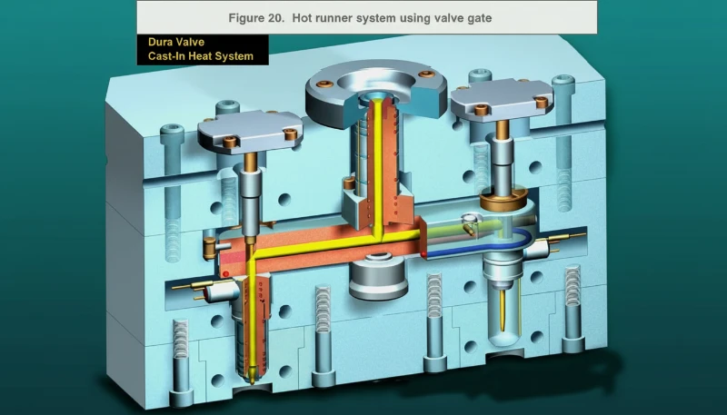
Hot runner systems eliminate cold-runner waste and reduce cycle time, but they also introduce a set of failure modes that can stop production entirely. A single thermocouple fault or a misaligned nozzle can cost hours of downtime and thousands of dollars in scrapped material. This guide covers the 11 most common hot runner problems engineers encounter in production, along with practical causes, diagnostic steps, and proven solutions drawn from over 20 years of injection molding experience at ZetarMold.
- Hot runner failures fall into four categories: thermal, mechanical, material contamination, and alignment issues.
- Thermocouple and heating-wire faults cause most hot runner downtime — check wiring and contacts first.
- Concentricity between cylinder body, manifold, and nozzle is critical; even small misalignment causes seizing.
- Preventive maintenance schedules reduce unplanned hot runner downtime significantly.
- Material leakage at combination surfaces usually traces back to incorrect expansion-gap calculations.
Why Can’t the Thermal Manifold Reach Set Temperature?
The thermal manifold is the heart of any hot runner system. When it fails to reach its target temperature, the entire molding cycle suffers — cold spots form, material viscosity spikes, and part quality degrades rapidly. In our experience, this is the single most frequent hot runner complaint, and the root cause almost always traces back to the electrical system rather than the mechanical design.
더 넓은 관점을 위해 우리의 injection molding complete guide 프로세스 기본 원리, 재료 행동 및 생산 결정을 포함합니다.
Common causes include: poor contact or outright failure of the thermocouple, a broken heating wire, heating wire wiring that is too loose or too short, and corroded terminal connections. Less obvious but equally damaging is a damaged temperature controller module that sends inconsistent signals.
솔루션: Start by checking whether the thermocouple contacts are secure and the wiring polarity is correct — reversed polarity is surprisingly common and causes the controller to read inaccurately. Next, measure the resistance of each heating wire zone; an open circuit confirms a break. Replace any damaged heating elements and re-terminate loose connections. For stubborn cases, swap the temperature controller with a known-good unit to isolate the fault. At ZetarMold, we maintain a hot runner spare-parts kit for every press precisely because these electrical faults can otherwise stall production for hours.
Why Does the Thermal Manifold Heat Up Too Slowly?
Slow heating usually means the manifold is losing heat faster than the heaters can supply it. A manifold should stabilize within 15–20 minutes; anything beyond 30 minutes signals a thermal efficiency problem. The root cause typically lies in heating elements, insulation gaps, or over-aggressive cooling circuits.
원인: A heating wire break or excessively loose wiring reduces delivered power. More commonly, insufficient air gap in the thermal manifold allows conductive heat loss to the mold base. Excessive cooling near the manifold — often from over-aggressive water circuits — steals heat faster than the heaters can supply it. Sometimes the issue is simply undersized heating elements for the manifold mass.
솔루션: Check all heating wires for continuity and replace any open-circuit elements. Increase the air gap to at least 10 mm between the manifold and the mold base, or install heat-insulation plates (mica or titanium plates work well). Verify that cooling circuits near the manifold are not over-cooling; reduce flow or redirect channels away from the manifold zone if necessary. For persistent slow heating, consult the hot runner manufacturer about upgrading to higher-wattage heater zones.
Why Is the Thermal Manifold Temperature Unstable?
Temperature instability is usually caused by poor thermocouple contact that introduces signal noise. The manifold oscillates plus or minus 10 to 20 degrees around setpoint, creating inconsistent melt viscosity that ruins part consistency across every cavity.
Primary cause: Poor thermocouple contact is the usual suspect. A loose or corroded thermocouple connection introduces signal noise that the controller interprets as temperature swings, causing it to over-correct. Secondary causes include PID controller1 parameters that are poorly tuned for the thermal mass of the manifold, and intermittent heating-element faults that deliver inconsistent power.
솔루션: Clean and reseat all thermocouple connections. If the thermocouple is surface-mounted, ensure the contact pad is clean, flat, and properly clamped. For persistent oscillation, re-tune the PID parameters — increase the proportional band and reduce the integral time to prevent overshoot. Replace any thermocouple that shows erratic readings under load. A stable ±2 °C band is the production target for most engineering resins.
How Do Metal Fragments Get Into the Melt and How Do You Prevent It?
The main sources of metal fragments in the melt are worn screw flight edges and contaminated raw material. These fragments damage gates, nozzle tips, and cavity surfaces while creating visible inclusions in finished parts, especially in transparent or light-colored resins.
원인: The two primary sources are debris on the injection molding machine screw (worn flight edges, plating flakes) and metal fragments in the incoming raw material (from regrind processing, damaged packaging, or contaminated silos). In rare cases, worn hot runner components inside the manifold shed metallic particles.
솔루션: Install or verify magnetic separators in the hopper and feed throat. Inspect the screw and barrel for wear during scheduled maintenance; replace the screw if flight edges show measurable wear. For regrind material, always pass through a metal-detection system before reintroducing to the hopper. Inside the hot runner, a filter nozzle or melt strainer can catch fragments before they reach the gates. At our Shanghai facility, we mandate metal-detection checks for every material lot entering production — a policy that has virtually eliminated contamination-related defects.

Why Does Material Leak at the Manifold-Nozzle Combination Surface?
Material leakage at the manifold-nozzle interface is most often caused by incorrect thermal expansion2 gap calculations. The leaking polymer wastes material and can insulate cooling channels or clog ejector pin holes if left unaddressed.
원인: The most common root cause is incorrect calculation of the thermal expansion gap. When the manifold heats from room temperature to 200–300 °C, it expands significantly. If the expansion amount was miscalculated — or if the machining height of the sealing surface (W surface) is inconsistent — the seal breaks under pressure. A damaged or worn fixed mold fixing plate (bottom plate) can also create a non-parallel sealing surface that leaks under clamp force.
솔루션: Recalculate the expansion amount using the actual operating temperature and the thermal expansion coefficient of the manifold material. Verify the W-surface machining height with a dial indicator — variation across the surface should be less than 0.02 mm. If the bottom plate shows wear or deformation, machine it flat or replace it. Always torque the manifold mounting bolts in the sequence specified by the hot runner manufacturer to ensure even sealing pressure.
Why Does the Manifold Compensation Plug Leak?
The manifold compensation plug leaks because the sealing gasket is missing, damaged, or incorrectly installed. The plug seals the channel at the end opposite the inlet, and any gap in the seal allows pressurized melt to escape into the mold structure.
원인: In the majority of cases, the plug was installed without the required gasket or sealing ring, or the gasket was damaged during installation. Less commonly, the plug seat is scored or corroded from previous leaks, preventing a clean seal.
솔루션: Disassemble and inspect the plug and seat. Install a new gasket or O-ring of the correct material and size (check the hot runner manual for the specified durometer and diameter). Clean the plug seat with fine abrasive paper if there is light scoring; replace the plug entirely if the seat is deeply damaged. During reassembly, apply the correct torque — over-torquing a soft-metal plug can deform the seat and create a new leak path.
Why Does the Oil or Gas Cylinder Fail to Operate?
Cylinder failure to operate typically means the pneumatic or hydraulic supply is interrupted or the piston is mechanically stuck. The cylinder controls valve-pin movement in valve-gated systems, so when it stops, production halts immediately.
원인: No air or hydraulic oil reaching the cylinder (supply failure), a stuck piston inside the cylinder, or insufficient system pressure. Sometimes the issue is external: a kinked hose, a closed valve in the supply line, or a failed solenoid on the controller board.
솔루션: Check the supply pipeline from the pump or compressor to the cylinder for leaks, blockages, and closed manual valves. Verify that system pressure meets the hot runner specification — typically 4–6 bar for pneumatic systems and 30–70 bar for hydraulic systems. If pressure is adequate but the cylinder does not move, disconnect the actuator rod and test the piston alone to determine whether the binding is in the cylinder or in the mechanical linkage to the valve pins.
What Causes the Cylinder System to Seize?
Cylinder seizing is different from a supply failure — the piston physically cannot move because of mechanical interference or thermal binding. The symptoms are similar (no gate action), but the root cause and fix are entirely different. Misdiagnosing a seizure as a pressure problem wastes time and can cause further damage if you increase system pressure trying to force a stuck piston.
원인: The cylinder body, hot manifold, and hot nozzle are not concentric — even 0.05 mm of offset can cause binding under thermal expansion. The fixed mold plate (bottom plate) accumulates excessive heat, which transfers to the cylinder body and causes differential expansion that locks the piston. Mechanical debris or galled metal on the piston rod can also prevent smooth travel.
솔루션: Using a dial indicator, measure concentricity of the cylinder bore, manifold bore, and nozzle bore — all three must align within 0.02 mm. If offset is found, adjust the mounting pads or use alignment dowels to correct the position. Add or increase cooling around the cylinder body to limit heat soak from the mold base. Polish any scoring on the piston rod and replace the rod seal. A properly aligned and cooled cylinder system should run for hundreds of thousands of cycles without seizing.
Why Does the Cylinder Block Overheat and Get Stuck?
Cylinder block overheating occurs when insufficient cooling allows heat from the manifold to soak into the cylinder body. The resulting thermal expansion closes internal clearances and locks the piston in place, a distinct mechanism from mechanical misalignment seizing.
원인: Lack of concentricity between the cylinder body, hot manifold, and hot nozzle causes uneven heat transfer. Insufficient cooling around the cylinder allows the temperature to climb above the design limit. In some cases, the cooling circuit design simply did not account for the actual heat load from a high-temperature manifold running engineering resins at 280–320 °C.
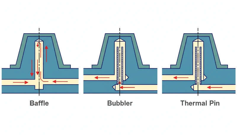
솔루션: Verify and correct concentricity as described in the previous section. Increase cooling flow around the cylinder block — if the mold design allows, add dedicated cooling channels or a baffle system specifically for the cylinder zone. For molds running high-temperature resins, consider a thermal break (insulation plate) between the manifold and the cylinder mounting surface. Monitor cylinder body temperature with a contact thermometer during production; if it exceeds 80 °C for pneumatic cylinders or 120 °C for hydraulic cylinders, the cooling is inadequate.
Why Does the Valve Needle Bushing Leak?
The valve needle bushing is a precision fit component that guides the valve pin through the manifold into the nozzle tip. A leak here means polymer escapes the intended flow channel, which can build up as a growing blob of material inside the mold structure. Over multiple cycles, this accumulated material can prevent the mold from closing fully, causing flash and dimensional problems that are easy to misattribute to clamp force.
원인: The bushing seat in the hot manifold is too loose — either machined oversized initially or worn from thermal cycling and repeated disassembly. The bushing diameter or height does not match the manifold bore, creating a gap that pressurized melt exploits.
솔루션: Measure the actual bore diameter and height in the manifold with a bore gauge, then compare against the bushing manufacturer specifications. If the bore is oversized, the manifold may need to be re-machined and fitted with an oversized bushing. If the bushing itself is the wrong size, simply replace it with the correct part. Apply a thin, even coat of high-temperature anti-seize compound during installation to prevent galling on future removals.
What Causes Valve Needle Head Sticky Material?
Sticky material on the valve needle head is a process-level problem rather than a mechanical defect. The valve needle tip does not fully separate from the polymer at the gate, leaving a thin film or string that builds up over cycles. Eventually, this accumulated material interferes with gate sealing, causes gate vestige3 defects, and can prevent the valve pin from fully closing.
원인: Excessive heat at the needle tip area — either the nozzle temperature is set too high for the resin, or cooling time is too short for the material to solidify and release cleanly from the needle surface. Some engineering resins (especially glass-filled nylons and high-temperature polycarbonates) are more prone to sticking due to their higher melt viscosity and adhesion characteristics.
솔루션: Reduce the hot nozzle temperature by 5–10 °C increments until gate quality improves. Increase cooling time by 1–2 seconds per cycle to allow the gate area to solidify. Verify that the gate cooling circuit is active and flowing adequately. If the material itself is the issue, a needle-tip coating (TiN or DLC) can reduce adhesion. In our production experience, fine-tuning nozzle temperature and cooling time resolves this issue in over 90% of cases without any hardware changes.
At ZetarMold, our Shanghai factory runs 47 injection molding machines from 90T to 1850T with an in-house mold manufacturing facility. Hot runner maintenance is built into our standard mold-care protocol — every hot runner mold receives a thermocouple and heater check before each production run, which has reduced hot-runner-related downtime to under 2% of scheduled production hours.
“Most hot runner failures can be diagnosed by systematically checking thermocouples, heating elements, and alignment before replacing any components.”True
A methodical diagnostic approach resolves the majority of hot runner issues without costly part replacements.
“Hot runner systems are maintenance-free once properly installed.”False
All hot runner systems require periodic thermocouple calibration, heater resistance checks, and seal inspections to maintain reliable performance.
Preventive maintenance is not optional for hot runner molds — it is the difference between predictable production and costly unplanned downtime. Establish a maintenance schedule that includes thermocouple calibration every 50,000 cycles, heater resistance checks after every production run, and complete manifold disassembly and cleaning at every mold pull. Keeping a documented maintenance log also supports warranty claims and helps predict when components are approaching end of life.
What Should You Check Before Ordering a Hot Runner Mold?
Before committing to a hot runner mold, buyers should verify that the tooling decision matches the production reality. Hot runner systems add cost and complexity to a mold, and they only deliver a return when production volumes justify the investment. A well-specified RFQ protects both buyer and supplier from costly mid-project changes.
Critical checks before ordering include: annual volume estimate, since hot runners typically justify their cost above 100,000 parts per year; resin type and melt temperature range, because high-temperature or corrosive materials require specialized components such as beryllium copper nozzles or nickel-coated manifolds; number of cavities and gate locations, which determine manifold layout and flow balancing complexity; cosmetic requirements for gate vestige, which influence the choice between thermal and valve gates; and available press tonnage and platen size, which constrain the maximum mold dimensions and manifold configuration.
The RFQ should also specify the hot runner brand and model number, maintenance requirements and intervals, spare-parts availability and lead times, and warranty terms including coverage for heater and thermocouple failures. A supplier who proactively includes this information in their quotation demonstrates production experience with hot runner systems and reduces the risk of unexpected tooling costs during production.
For a comprehensive overview of tooling decisions, see our injection mold guide covering design considerations, steel selection, and maintenance planning for production molds. When evaluating potential suppliers for hot runner molds specifically, our sourcing guide provides a structured framework for comparing tooling capabilities, lead times, and total cost of ownership across multiple quotation scenarios. These resources complement the technical checks described above with practical procurement guidance.
What Production Evidence Proves Hot Runner Reliability?
When you are auditing a supplier or qualifying a new hot runner mold, the best evidence is production data, not marketing claims. Ask for molding trial records that show temperature stability across all zones over a minimum 2-hour continuous run. Request dimensional inspection data from first articles through the end of the trial to confirm part consistency.
A strong supplier will provide gate quality photos from the trial, melt-pressure traces from each cavity, and cycle-time records showing stable production. They should also be able to explain their hot runner maintenance schedule and spare-parts inventory policy. The strongest signal is a supplier who connects tooling choices to production outcomes — for example, explaining why they chose a particular gate type and how it affects gate vestige for your specific resin and geometry.
“Valve-gated hot runner systems generally produce better gate quality than thermal-gated systems for cosmetic parts.”True
Valve gates provide positive mechanical shutoff, which eliminates stringing and reduces gate vestige compared to thermal gates that rely on temperature balance.
“Increasing system pressure always fixes cylinder operation problems in hot runner systems.”False
Excessive pressure on a seized cylinder can bend the piston rod or damage the cylinder bore, turning a repairable problem into a replacement scenario.
자주 묻는 질문
자주 묻는 질문
What are the most common hot runner system failures?
The most frequent hot runner failures include thermocouple faults, heating wire breaks, manifold temperature instability, material leakage at sealing surfaces, and cylinder seizing in valve-gated systems. Thermal-related issues account for roughly 40 percent of all hot runner downtime in production environments. Most of these failures are preventable with regular maintenance schedules, proper installation procedures, and a well-stocked spare-parts kit kept at the press. Buyers evaluating injection molding suppliers should always ask about hot runner maintenance protocols and documented uptime records as part of their qualification process.
How do you troubleshoot a hot runner manifold that will not heat up?
Begin by checking the thermocouple contacts and wiring polarity, because reversed polarity is a surprisingly common installation error that causes the controller to read inaccurately. Next, measure the resistance across each heating zone with a multimeter to identify any open circuits from broken heating wires. If all electrical components test within specification, verify the temperature controller output and swap it with a known-good unit to isolate whether the fault lies in the controller or the manifold hardware. This systematic approach from sensor to heater resolves most heating failures without replacing expensive manifold components.
How often should hot runner systems be maintained?
Hot runner maintenance should be performed at every mold pull or at minimum every 100,000 cycles, whichever occurs first. A thorough maintenance check includes thermocouple calibration against a reference standard, heater resistance measurement and recording, seal and gasket inspection for deformation or hardening, nozzle tip examination for wear or carbon buildup, and complete cleaning of all melt flow channels. For molds running high-temperature engineering resins above 300 degrees Celsius or corrosive materials such as flame-retardant grades, maintenance intervals should be reduced to every 50,000 cycles to catch accelerated wear early.
What causes flash in hot runner molds?
Flash in hot runner molds can result from several distinct root causes that require different fixes. Insufficient clamp force for the projected cavity area is the most common cause. Worn gate seals allow material to bypass the shut-off surface. Material leakage at the manifold-nozzle interface from incorrect thermal expansion calculations pushes polymer into parting lines. Excessive packing pressure can also force material into mold seams. In valve-gated systems specifically, a leaking valve needle bushing or a stuck valve pin creates localized flash at the gate area. Systematic diagnosis should check each of these potential causes in order of likelihood.
Can hot runner problems cause part defects?
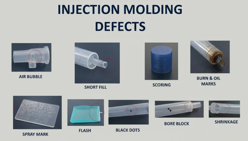
Yes, hot runner issues directly cause several common injection molding part defects. Temperature instability across manifold zones leads to inconsistent fill patterns and dimensional variation between cavities in the same cycle. Metal contamination from worn internal components creates visible inclusions, especially problematic in transparent or light-colored parts. Nozzle and seal leaks cause flash and parting-line defects on the mold surface. Valve needle sticking produces unacceptable gate vestige and stringing on cosmetic surfaces. In many production scenarios, addressing the underlying hot runner condition is the fastest and most cost-effective path to improving part quality without adjusting processing parameters.
What is the difference between thermal gate and valve gate hot runner systems?
Thermal gates rely on the balance between heater temperature and mold cooling at the gate tip to control material flow, and the gate freezes shut thermally when the mold opens. Valve gates use a mechanically actuated pin that positively opens and closes the gate with independent timing control. Valve gates produce noticeably better gate quality with minimal vestige, allow independent cavity timing for family molds, and are strongly preferred for cosmetic parts, engineering resins, and multi-cavity tools. However, valve gate systems add cost and require periodic maintenance of the cylinder and pin mechanism, so the selection should match your production volume and quality requirements.
How do you prevent material leakage in hot runner systems?
Prevention begins with correct thermal expansion calculations during the initial mold design phase, using actual operating temperatures and the specific expansion coefficient of the manifold steel. Ensure all sealing surfaces are machined flat to tolerances under 0.02 mm, gaskets and O-rings are installed in the correct orientation and in good condition, mounting bolts are torqued in the sequence specified by the hot runner manufacturer, and manifold-to-nozzle alignment is verified with dial indicators during mold assembly. Regular scheduled replacement of seals and gaskets during planned maintenance prevents the gradual leak development that accumulates over thousands of production cycles and eventually causes visible flash or internal mold contamination.
What are the 4 stages of injection molding?
The four stages of injection molding are clamping, injection, cooling, and ejection. During clamping the mold halves close under hydraulic or mechanical force. During injection molten plastic fills the cavity through the runner and gate system under high pressure. During cooling the molded part solidifies while the mold maintains precise temperature control through internal water circuits. During ejection the mold opens and the finished part is removed by ejector pins or plates. The hot runner system plays a critical role during injection and cooling, delivering consistent melt temperature and uniform packing pressure to every cavity, which directly determines part quality, dimensional accuracy, and cycle time.
-
PID controller: A PID controller is a feedback control loop mechanism using proportional, integral, and derivative terms to maintain a process variable at its setpoint, the standard controller type used for hot runner temperature regulation. ↩
-
thermal expansion: 열팽창은 선형 팽창 계수에 원래 길이와 온도 변화를 곱하여 계산되는, 온도 상승에 따른 금속 구성 요소의 치수 변화를 의미합니다. ↩
-
gate vestige: 게이트 베스티지는 게이트 유형과 가공 조건에 따라 크기와 외관이 결정되는, 러너 시스템에서 분리된 후 성형품의 게이트 위치에 남아 있는 플라스틱의 작은 흔적이나 잔여물을 의미합니다. ↩


