 コンテンツへスキップ

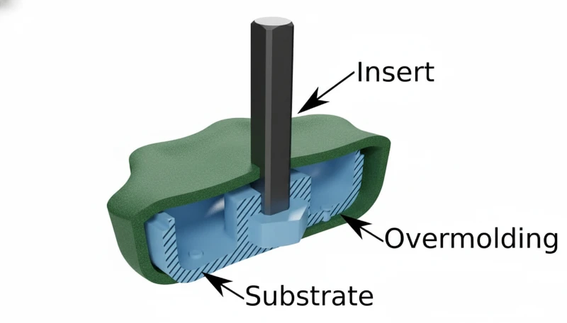
- オーバーモールドは、2つの異なる材料を単一部品に結合し、最も一般的には硬質基材(ABS、PC、ナイロン)を軟質熱可塑性エラストマー(TPE)で覆い、組み立てステップを40-60%削減します。
- 材料の互換性は、最も重要な成功要因です:基材はオーバーモールド材料よりも高い融解温度を持つ必要があり、化学的接着には2 (cal/cm³)^0.5以内の溶解度パラメータの一致が必要です。
- 回転プラテンプレスでのツーショットオーバーモールドでは、1部品あたり25〜45秒のサイクルタイムが得られます。一方、ピックアンドプレースオーバーモールドでは、基材の移送に10〜15秒追加されますが、設備投資は少なくて済みます。
- オーバーモールド層の肉厚は、十分な充填と接着のために1.0〜3.0 mmとし、ショートショットを防ぐためにどの点でも最低0.5 mmを確保する必要があります。
- 一般的な欠陥には、剥離(接着不良)、基材-オーバーモールド界面でのフラッシュ、および40 MPaを超えるオーバーモールド射出圧力による基材の変形が含まれます。
What Is Overmolding and How Does It Work?
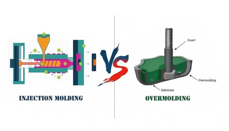
オーバーモールドは、2段階の射出成形プロセスであり、通常は柔らかい 熱可塑性エラストマー1—を予備成形された硬質基材の上に成形し、1つの製造工程で単一の多材料部品を生産します。このプロセスにより、多材料製品にコスト、故障点、生産時間を追加する手作業での組み立て、接着剤による接合、機械的ファスナーが不要になります。
基材は、基本樹脂の標準射出成型パラメータを使用して最初に成型されます。部分的または完全な冷却後、基材は第二キャビティに転送される(ピック&プレース方式)か、多ステーションプレス上で位置に回転されます(二射成型方式)。その後、オーバーモールド材料が基材上に射出され、化学接着、機械的インターロック、または両方によって結合します。
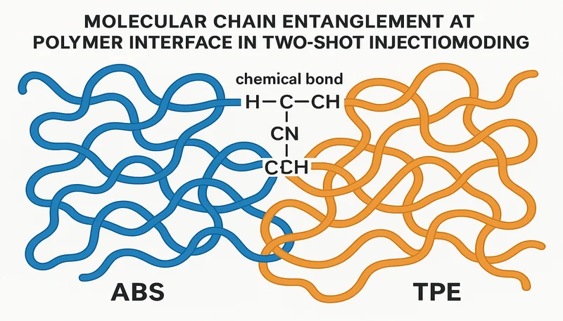
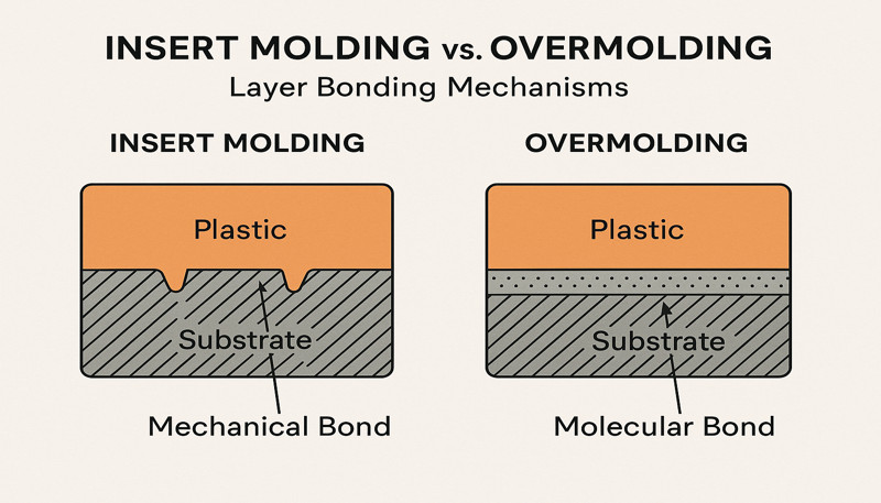
化学結合は、オーバーモールドの溶融が基材表面を部分的に再溶融し、界面で分子の絡み合いを生じる時に発生します。この機構は適合するポリマー化学が必要です—ABS上の熱可塑性エラストマーは剥離試験で150–300 Nの結合強度を達成しますが、TPEとポリエチレンなどの非適合ペアは機械的特徴なしではほぼゼロの接着力を生みます。
| Method | サイクルタイム | 資本コスト | 最適 |
|---|---|---|---|
| ツーショット(回転プラテン) | 25〜45秒 | $150K–$400K | 高容量生産(>100K個/年) |
| ピック&プレース(転送) | 35〜60秒 | $80K–$200K | 中量生産、複雑な基材 |
| マルチショット (3+材料) | 40–70秒 | $300K–$600K | 多色または多硬度部品 |
| オーバーインサートハイブリッド | 30〜50秒 | $100K–$250K | 金属基材 + プラスチックオーバーモールド |
二射成型とピック&プレースの選択は、生産量と部品の複雑さに依存します。回転プラテンを持つ二射成型プレスは転送時間を排除し、基材とオーバーモールド間のより厳密な位置公差(±0.05 mm)を生み出します。ピック&プレース方式は2つの別々の単射成型機を使用し、ステーション間で回転できない基材形状に対してより柔軟性を提供します。
成功したオーバーモールドには、3つの重要なパラメータの精密制御が必要です:オーバーモールド射出時の基材表面温度(理想的には環境温度より40–80°C高い)、オーバーモールド溶融温度(材料供給者の推奨範囲内)、射出圧力(通常、壁厚と流動長に依存して30–80 MPa)。いずれかのパラメータからの逸脱は、結合強度と部品品質に直接影響します。
オーバーモールドに互換性のある材料はどれですか?
材料の適合性は80%のオーバーモールドの成功または失敗を決定し、TPE-to-ABSとTPE-to-PCは商業生産において最も信頼性のある2つの組み合わせです。基材は第二射の際に基材の変形を防ぐため、オーバーモールド材料よりも融点が最低40°C高い必要があります—ABS(融点220–260°C)とTPE(180–220°C)の組み合わせは、十分な安全マージンを持ってこの要件を満たします。
化学的接着強度は、2つのポリマー間の溶解度パラメータの一致に依存します。溶解度パラメータが互いに2 (cal/cm³)⁰·⁵以内の材料は、強力な化学的結合を形成します。スチレン系TPE(SEBSベース)は、ABSおよびポリスチレンによく接着します。これは、3つすべてが類似したスチレンベースの化学構造を共有しているためです。ポリエステルベースのTPEは、界面でのエステル交換反応により、PBTおよびPCに接着します。
| 基材 | 適合オーバーモールド | 結合タイプ | 剥離強度 (N) |
|---|---|---|---|
| ABS | TPE (SEBSベース) | 化学的 + 機械的 | 150–300 |
| PC | TPE(ポリエステル系) | 化学的 | 120~250 |
| PA6/PA66 (Nylon) | TPE(ポリアミド系) | 化学的 | 100~200 |
| PP | TPE(PP系、TPV) | 化学的 | 80–150 |
| POM (Acetal) | TPE(任意) | 機械的のみ | 30–60 |
| 高密度ポリエチレン | TPE(任意) | 機械的のみ | 20–50 |
| ISO 10993: | TPE(SEBSまたはポリエステル系) | 化学的 | 130–270 |
POM、HDPE、PEEK基材のように化学的接着が不可能な場合、機械的インターロックが唯一信頼できる接続を提供します。基材上の貫通穴、アンダーカット、溝、およびテクスチャ表面がオーバーモールド材料を物理的に捕捉します。これらの機械的特徴は、予想される使用荷重に耐えるのに十分な深さ(最低0.3 mm)が必要であり、その間隔は界面全体に応力をどのように均一に分散させるかを決定します。
シリコーンオーバーモールドは特殊なケースであり、基材にプライマー塗布またはプラズマ表面処理が必要です。液体シリコーンゴム(LSR)は、表面活性化なしではどの熱可塑性プラスチックとも化学的に接着しません。プライマーを用いた接着は工程が追加されますが、80–150 Nの接着強度を達成し、医療機器シール、防水ガスケット、-40°Cから+200°Cの温度にさらされる自動車コネクターに適しています。
オーバーモールド層のショア硬さは完成部品の触感を決定します。ショアA 40~60は手工具や歯ブラシに好まれる柔らかくクッション性のあるグリップを生み出します。ショアA 70~85は電子機器ハウジングや自動車コントロールに適したより固い表面を提供します。適切な硬さの選択には、ユーザーの快適性と耐摩耗性のバランスが必要です—柔らかい材料は繰り返しの摩擦接触でより早く摩耗します。
基材とオーバーモールドの色合わせにも材料の考慮が必要です。半透明のTPEオーバーモールドは基材の色を透かして見せることができ、塗装なしで単一材料の色効果を実現します。不透明のTPEグレードは基材を完全に隠し、基材の色が不均一な場合(再生樹脂、ミネラル充填コンパウンド)に好まれます。異なる色のTPEを順次射出する多色オーバーモールドは、成形後の装飾なしに、電動工具ハンドルの象徴的なツートーングリップなど、ブランド固有のパターンを作り出します。
「TPEからABSへのオーバーモールドは、表面プライマーや機械的構造を必要とせずに、150–300 Nの化学的接着強度を達成します。」真
SEBSベースのTPEとABSはスチレン系化学を共有しており、オーバーモールド射出時に基材表面温度が60°Cを超えると界面で分子鎖の絡み合いを可能にします。この化学的適合性により、TPE/ABSは電動工具のグリップからパーソナルケア機器まで、消費財で最も広く使用されるオーバーモールディングの組み合わせとなっています。
「射出パラメータが正しく最適化されていれば、どのような2つのプラスチックでもオーバーモールドすることが可能です。」偽
材料化学がオーバーモールドの適合性を根本的に制限します。POM、HDPE、PEEKは表面エネルギーが低く、非極性の分子構造を持つため、プロセス最適化に関わらず、どのTPEとも化学的に接着しません。これらの基材には、部品形状に設計された機械的インターロック構造が必要です。ポリマー化学が適合しない場合、温度や圧力の調整をどれだけ行っても化学的接着は生まれません。
オーバーモールド部品の主要な設計ガイドラインは何ですか?
1.0~3.0 mmのオーバーモールド肉厚は、キャビティの完全充填、適切な接着形成、許容可能なサイクル時間を確保する最適範囲です。1.0 mm未満では、溶融体が充填末端に到達する前に凍結し、ショートショットと弱い接着を引き起こします。3.0 mmを超えると、冷却時間が指数関数的に増加します—4.0 mmのオーバーモールド層は2.5 mm層より60%多くの冷却時間を必要とし、サイクルごとに8~12秒追加されます。
基材-オーバーモールド境界でのシャットオフ設計は、材料遷移部で金型表面間にしみ出る薄い材料の膜であるバリを防止します。0.01~0.02 mmのクリアランスと3~5°の干渉角を持つスチール対スチールのシャットオフは、500,000サイクル以上にわたる信頼性のあるシールを提供します。雄雌構造設計は、より高い金型コストでさらに優れたバリ制御を提供します。
| パラメータ | 推奨範囲 | 違反の影響 |
|---|---|---|
| オーバーモールド肉厚 | 1.0–3.0 mm | ショートショット(1.0未満)または長サイクル(3.0超) |
| シャットオフクリアランス | 0.01~0.02 mm | 界面でのバリ(>0.03 mm) |
| 基材の抜き勾配 | 1.5–3.0° | エジェクション損傷(1.0°未満) |
| 機械的インターロック深さ | ≥0.3 mm | 荷重下での接着破壊(0.2 mm未満) |
| ゲートから最遠端までの流動比 | ≤100:1 | 充填不足または溶接ライン |
| 基材表面粗さ | Ra 1.6–6.3 μm | 接着不良(Ra 0.8未満) |
オーバーモールドショットのゲート配置は、単一材料成形とは異なる規則に従います。ゲートは、オーバーモールド領域の最長寸法に沿って溶融樹脂の流れを導き、ゲートから最遠点までの流動経路は、流動長さと肉厚の比が100:1を超えてはなりません。ファンゲートやフィルムゲートは、ピンゲートよりも溶融樹脂を均等に分散し、目に見える外観不良や潜在的な接着弱部を生むウェルドラインを減少させます。
基材表面の準備は接着品質に大きく影響します。Ra 1.6~6.3 μmの表面粗さは、オーバーモールド材料に最適な微細機械的固定を提供します。高度に研磨された基材(Ra 0.8 μm未満)は、オーバーモールドが掴む表面形状を持たないため、接着力を低下させます。基材の接着面をEDM放電加工または化学エッチングでテクスチャリングすると、平滑面に比べて剥離強度を30~50%向上させることができます。
A thorough DFM5 金型製作前に設計問題をレビューすることで、金型鋼材切削後の修正コストを削減。オーバーモールドプロジェクトにおける一般的なDFM指摘には、基材の抜き勾配不足(取り出し損傷の原因)、オーバーモールド部の肉厚不足による充填不良、5万サイクル後にバリを生じるシャットオフ形状などがある。設計段階でこれらの指摘に対処することで、プロジェクトごとに金型修正費を$5,000〜$15,000節約可能。
最も一般的なオーバーモールドの欠陥と解決策は何ですか?
デラミネーション(オーバーモールドが基材から剥離すること)は最も重大なオーバーモールド不良であり、材料適合性が事前に検証されていない場合、初回試作の35%で発生します。根本原因は、常に界面での接着強度不足であり、それは材料の不適合、基材表面温度の低さ、表面汚染、または不十分な機械的インターロック構造によるものです。
基材変形は、オーバーモールド射出圧力が高温時の基材のたわみ抵抗を超えたときに発生します。薄肉基材(肉厚1.5 mm未満)は特に脆弱です—60 MPaの射出圧力は1.0 mmのABS基材を0.3~0.5 mmたわませ、寸法誤差と目に見える外観欠陥を生じさせます。射出速度と圧力を低減するか、金型コアの構造で基材を支持することで、この欠陥を防止できます。
| 欠陥 | Root Cause | 第一の対策 | エネルギー消費量: |
|---|---|---|---|
| Delamination | 不適合な材料または低温の基材 | 基材の予熱温度を60–80°Cに上げる | 剥離試験で材料ペアを検証 |
| インターフェースでのフラッシュ | 摩耗したシャットオフまたは過剰なクランプ圧力 | シャットオフ表面の再切削 | 雄雌式(つぎはぎ)のシャットオフを設計 |
| ショートショット(オーバーモールド) | 薄肉部が早期に凍結 | 溶融温度を10~20°C上げる | 最小1.0 mmの肉厚に再設計 |
| 基材の反り | Injection pressure too high | 充填率を20–30%削減 | 型にコアサポート機能を追加 |
| 溶接ライン | Multiple flow fronts meeting | ゲート位置の再配置 | シーケンシャルバルブゲーティングを使用 |
基材-オーバーモールド界面でのフラッシュは、シャットオフ表面が繰り返し型循環で摩耗するにつれて徐々に蓄積する。新しい型は通常100,000–200,000循環フラッシュなしで運転し、その後鋼-鋼接触表面が鋭いエッジを失う。予防保守には、150,000循環ごとにシャットオフ表面を再切削し、高摩耗シャットオフ位置で硬化鋼インサート(HRC 52–58)を使用して保守間隔を400,000+循環に延長する。
溶接ラインは、オーバーモールド充填中に2つ以上の溶融フロントが収束する場所で形成されます。主に見た目上の問題である単一材料の溶接ラインとは異なり、オーバーモールドの溶接ラインは、どちらの流れフロントも基材に十分な圧力で接触せず、接着が形成されない結合のない領域を作り出すことがあります。シーケンシャルバルブゲーティング—ゲートが同時ではなく時間をずらして開く—は、収束する流れフロントを排除し、溶接ラインのない部品を生産します。
厚いオーバーモールドセクションの反対側にある基材側のシンクマークは、もう一つの繰り返し発生する問題です。オーバーモールド層が局所的に3.0 mmを超えると、集中した熱量により基材が再軟化し、内側に収縮します。どの断面でもオーバーモールドの厚さを最大2.5 mmに制限するか、厚いオーバーモールドゾーンの真下に冷却チャネルを追加することで、ケースの90%で基材側のシンクマークを排除できます。
色の滲みは、両表面が軟化温度以上である短い期間に、オーバーモールド材料中の色素が基材に移行するときに発生する。この欠陥は、明るい基材上の暗いオーバーモールドで最も目立つ。カラー粒子がポリマー微小球内に閉じ込められたカプセル化色素システムを持つTPEグレードを使用すると、処理温度が高くなっても移行を防止する。
「オーバーモールド射出前に基材を60–80°Cに予熱すると、室温の基材と比較して接着強度が40–70%向上します。」真
高い基材温度は、オーバーモールド接触時に界面ゾーンをガラス転移温度以上に保ち、境界を越えるポリマー鎖の拡散を可能にする。TPE/ABSペアの工業試験では、剥離強度が25°C基材温度で120 Nから70°Cで210 Nに増加し、基材軟化が寸法リスクを導入する90°C以上では減少する利益が見られる。
「オーバーモールドの欠陥は、金型や部品設計を変更せずにプロセスパラメータを調整することで常に修正可能です。」偽
プロセス最適化には限界があります。非互換性材料からの剥離は、プロセスの変更ではなく材料の変更を必要とします。摩耗したシャットオフ面からのフラッシュは金型修理を必要とします。0.5 mm未満の薄肉部でのショートショットは、肉厚を増やすための設計修正を必要とします。生産におけるオーバーモールド欠陥の約40%は、プロセスパラメータ調整だけでは解決できない金型または設計の変更を必要とします。
どの業界がオーバーモールドを使用し、なぜですか?
消費者向け電子機器は、スマートフォン、ウェアラブル、電動工具におけるソフトタッチグリップ、密閉筐体、マルチカラー美学への普遍的な需要により、世界のオーバーモールド需要の30%を占めています。単一のオーバーモールドされた電話ケースは、3ピースアセンブリ(ハードシェル+ゴムバンパー+接着剤)を置き換え、50万個以上の量産ではユニットあたりの製造コストを$0.15–$0.40削減します。
医療機器は最も急速に成長するオーバーモールドセグメントであり、年間8–12%で拡大している。外科器具は、湿った手術環境での滑り止めハンドリングを提供する、ステンレス鋼またはポリカーボネート基材上のショアA 50–65 TPEの人間工学グリップを必要とする。オーバーモールド層は内部電子機器を流体侵入から密封し、追加のガスケットや二次密封作業なしにIP67またはIP68評価を達成する。
自動車内装部品は、ダッシュボードスイッチ、ステアリングホイールコントロール、ドアハンドルに広くオーバーモールドを採用しています。オーバーモールド層は、一貫した触覚フィードバック(ショアA 70~85)、紫外線耐性(SAE J2527に基づくキセノンアーク試験最低1,000時間)、ハンドクリーム、日焼け止め、洗浄溶剤に対する耐化学性を提供します。オーバーモールドされた各スイッチは、機械的に固定されたゴム・オーバー・プラスチックの代替品と比較して、2~3の組み立て工程を削減します。
| 産業 | 代表的なアプリケーション | Key Requirement | 組立との比較によるコスト削減 |
|---|---|---|---|
| 家電製品 | スマホケース、工具グリップ | ソフトタッチ感、落下保護 | 1ユニットあたり15~25 |
| 医療機器 | 外科器具、薬剤送達 | 生体適合性、IP67密封 | ユニットあたり20–35% |
| 自動車 | スイッチ、ノブ、ハンドル | UV安定性、耐薬品性 | 10–20% 単位 |
| 産業用工具 | 電動工具ハンドル、振動吸収グリップ | 衝撃吸収、疲労寿命 | 15–30% 単位 |
| Personal care | 歯ブラシ、かみそり | ソフトグリップ、防湿シール | 25–40% 単位 |
産業用電動工具は、グリップの快適性に加えて、振動吸収のためにオーバーモールドを活用しています。ナイロン製工具ハウジングに施された2.0 mmのTPEオーバーモールド層は、伝達される振動エネルギーの20~35%を吸収し、ISO 5349で規定される1日あたりの作用値2.5 m/s²を下回るレベルまで作業者の手・腕への振動曝露を低減します。この機能的な利点により、無加工のプラスチックハウジングと比較して1ユニットあたり0.30~0.80のコスト増加が正当化されます。
1990年代に大量生産のオーバーモールドを先導し、プロセス効率の基準として今も残る個人用ケア製品—歯ブラシ、剃刀、ヘアスタイリングツール。現代の歯ブラシ生産ラインは15秒周期で4–8キャビティの工具をオーバーモールドし、単一プレスで一日に40,000–80,000個のハンドルを生産する。オーバーモールドはグリップのテクスチャと、競合ブランドを店頭で区別する色のアクセントを両方提供する。
航空宇宙セクターは、-55°Cから+125°Cで確実に動作する必要がある振動減衰マウントブラケットと密封コネクタハウジングにオーバーモールドを採用した。PEEKまたはPEI基材上のフルオロエラストマー(FKM)オーバーモールドは、ジェット燃料、油圧流体、除氷化学物質に耐えながら、敏感な航空電子機器をエンジン伝達共振周波数から保護する振動隔離を提供する。
オーバーモールドはインサート成形と比較してどうですか?
オーバーモールドと インサート成形2 両者は単一部品に複数の材料を組み合わせるが、基材タイプとプロセス順序が異なる—オーバーモールドはプラスチック-プラスチック(またはプラスチック-TPE)を結合し、インサート成形は通常、ねじ込みインサート、電気接触、または構造補強などの金属部品をプラスチック本体内に封入する。
オーバーモールディングにおける基材は、常に最初に射出成形されます—同じサイクル内(ツーショット)または別の事前作業(ピックアンドプレース)で行われます。インサート成形では、基材は成形前に金型内に配置される事前成形部品(打抜き金属、機械加工黄銅、ワイヤーハーネス)です。この違いは金型設計に影響します:オーバーモールド金型は2つの射出ユニットと2つのキャビティセットが必要ですが、インサート成形金型は1つの射出ユニットと自動化された基材ローディングシステムが必要です。
| ファクター | オーバーモールディング | インサート成形 |
|---|---|---|
| Substrate material | Injection-molded plastic | Metal, pre-formed plastic, wire |
| Bonding mechanism | 化学的 + 機械的 | Mechanical encapsulation |
| Typical cycle time | 25–45 sec (two-shot) | 20–40 sec (single-shot + load) |
| Tooling cost | $150K–$400K | $80K–$200K |
| Bond strength | 150–300 N (peel) | Depends on encapsulation geometry |
| Best application | Soft-touch grips, sealed housings | Threaded inserts, electrical contacts |
Cost comparison favors insert molding for parts requiring metal functionality (threads, conductivity, structural strength) and overmolding for parts requiring multi-material aesthetics or tactile properties. A threaded metal insert encapsulated in nylon costs $0.08–$0.15 less per part than a separately assembled threaded insert. An overmolded soft-grip handle costs $0.20–$0.40 less than an adhesive-bonded rubber sleeve over a rigid handle.
Many products use both processes in a single part. An electric drill handle, for example, uses insert molding to encapsulate brass threaded inserts and electrical contacts, followed by overmolding to apply the soft-touch TPE grip surface. This combination delivers metal-to-plastic structural connections and plastic-to-TPE ergonomic surfaces in a three-material part that would require 6–8 assembly steps if manufactured with conventional methods.
Zetarはオーバーモールドプロジェクトをどのように扱いますか?
Zetar’s engineering team runs 金型流動解析3 on every overmolding project before cutting tool steel, simulating both the substrate shot and the overmold shot to predict fill patterns, bond-line temperatures, and potential defect locations. This dual-simulation approach identifies the 85% of potential overmolding failures that originate in material selection and gate placement decisions made before any tooling work begins.
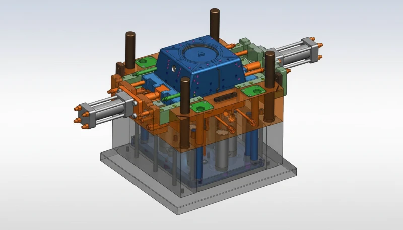
With 47 injection molding machines from 50 to 1,600 tons—including multi-component presses with rotary platens—Zetar processes overmolding projects from prototype quantities of 100 parts through production runs exceeding 1,000,000 annually. The facility maintains dedicated material compatibility testing equipment, including peel-test fixtures that validate substrate-overmold bond strength before committing to production tooling.
Zetar’s 射出成形金型設計4 process includes shut-off optimization using wear simulation to predict maintenance intervals, ensuring that flash-free production extends to 300,000+ cycles before the first scheduled shut-off re-cut. Combined with a 92% first-pass yield rate on overmolding projects, this approach reduces the typical 3–4 mold iterations to 1–2, saving clients $10,000–$30,000 and 4–8 weeks per project compared to industry averages.

オーバーモールドに関するよくある質問?
What is the difference between overmolding and two-shot molding?
Overmolding is the broad category that includes any process bonding one material over another. Two-shot molding is a specific overmolding method where both materials are injected in the same mold using a machine with two injection units and a rotating platen. The substrate is molded in the first station, the platen rotates 180 degrees, and the overmold is injected in the second station—all within a single automated cycle of 25–45 seconds. Pick-and-place overmolding, the other main method, transfers the substrate between separate molds and machines. Two-shot is faster and more precise but requires higher capital investment ($150K–$400K vs $80K–$200K for pick-and-place tooling).
Can you overmold silicone onto plastic?
Yes, but silicone (LSR) does not chemically bond to any thermoplastic without surface treatment. The standard approach uses a primer—applied to the substrate before it enters the mold—that creates a reactive interface layer enabling silicone adhesion. Plasma or corona surface treatment is an alternative that activates the substrate surface without adding chemical primers. Bond strength with primer-based methods reaches 80–150 N in peel tests, sufficient for medical seals, waterproof gaskets, and high-temperature connectors. The additional primer step adds $0.02–$0.05 per part and 5–10 seconds to the cycle. For applications below 150°C, TPE overmolding provides equivalent sealing performance without primers.
What materials cannot be overmolded together?
POM (acetal), HDPE, and PEEK are the most difficult substrates for overmolding because their low surface energy and non-polar molecular structures prevent chemical bonding with any thermoplastic elastomer. These materials can only be overmolded using mechanical interlocking features—through-holes, undercuts, and grooves molded into the substrate—that physically trap the overmold material. Even with mechanical features, bond strength is limited to 30–60 N compared to 150–300 N for chemically compatible pairs. PP requires a specifically formulated PP-based TPV (thermoplastic vulcanizate) for reliable chemical bonding, as standard SEBS-based TPEs do not adhere well to polypropylene substrates.
How much does overmolding add to part cost?
Overmolding adds $0.10–$0.80 per part depending on overmold volume, material choice, and process method. The overmold material itself costs $0.03–$0.15 per part (TPE at $3–$8 per kg, typical overmold weight 2–10 grams). The process cost adds $0.05–$0.30 per part for the additional injection cycle time. Tooling amortization adds $0.02–$0.35 per part depending on production volume and mold complexity. However, overmolding eliminates assembly labor ($0.15–$0.60 per part), adhesive material ($0.05–$0.15), and quality inspection of bonded assemblies ($0.03–$0.10). Net cost impact is often neutral or negative at volumes above 50,000 parts annually.
What wall thickness should the overmold layer be?
The optimal overmold wall thickness is 1.0–3.0 mm for most TPE applications. At 1.0 mm, the melt has sufficient flow length to fill moderately complex geometries (flow-length-to-thickness ratio up to 100:1) while maintaining enough heat to bond with the substrate. At 3.0 mm, cooling time remains manageable at 15–25 seconds. Below 1.0 mm, the melt freezes before reaching the cavity extremities, causing short shots and unbonded regions. Above 3.0 mm, cooling time increases sharply—a 5.0 mm overmold requires 40+ seconds of cooling. The absolute minimum at any point is 0.5 mm to prevent complete freeze-off during injection.
How do you test overmolding bond strength?
The standard test method is a 90-degree or 180-degree peel test per ASTM D1876, where the overmold layer is pulled away from the substrate at a controlled rate (typically 50–300 mm per minute) while a load cell records the force required. Results are reported in Newtons per unit width (N/25 mm is standard). For production quality control, a simpler manual peel test at designated witness tabs on the part provides a pass/fail result—if the overmold tears cohesively (within the TPE layer) rather than delaminating at the interface, the bond is adequate. Cross-hatch adhesion testing per ASTM D3359 is used for thin overmold layers below 0.5 mm.
Does overmolding work for low-volume production?
Yes, pick-and-place overmolding is economically viable for volumes as low as 1,000–5,000 parts. This method uses two separate single-cavity molds—one for the substrate and one for the overmold—with manual or robotic transfer between them. Tooling cost is $80K–$200K total, significantly less than two-shot rotary tooling. For prototype quantities under 500 parts, 3D-printed substrates can be overmolded in soft-tooling (aluminum molds) at $5K–$15K tooling cost, though bond strength may be lower due to the porous surface of printed substrates. Silicone overmolding with vacuum casting is another low-volume option at $500–$3,000 per design iteration.
-
thermoplastic elastomer: A thermoplastic elastomer (TPE) is a class of copolymers that combines the rubber-like flexibility of elastomers with the melt-processability of thermoplastics, typically exhibiting Shore A hardness from 20 to 90. ↩
-
insert molding: Insert molding is an injection molding process in which a pre-formed component—typically metal—is placed into the mold cavity before plastic is injected around it, creating a single integrated part. ↩
-
mold flow analysis: Mold flow analysis refers to a computer simulation technique that predicts how molten polymer fills, packs, and cools inside a mold cavity, measured in fill time (seconds), pressure distribution (MPa), and weld-line location. ↩
-
injection mold design: Injection mold design is an engineering discipline that refers to the creation of tooling with optimized gate placement, parting lines, cooling channels, and ejection systems for producing dimensionally accurate plastic parts. ↩
-
DFM: DFM (Design for Manufacturability) is defined as a systematic engineering approach that evaluates part geometry, tolerances, and material selection against manufacturing process constraints to minimize cost and defect risk. ↩


