 Vai al contenuto

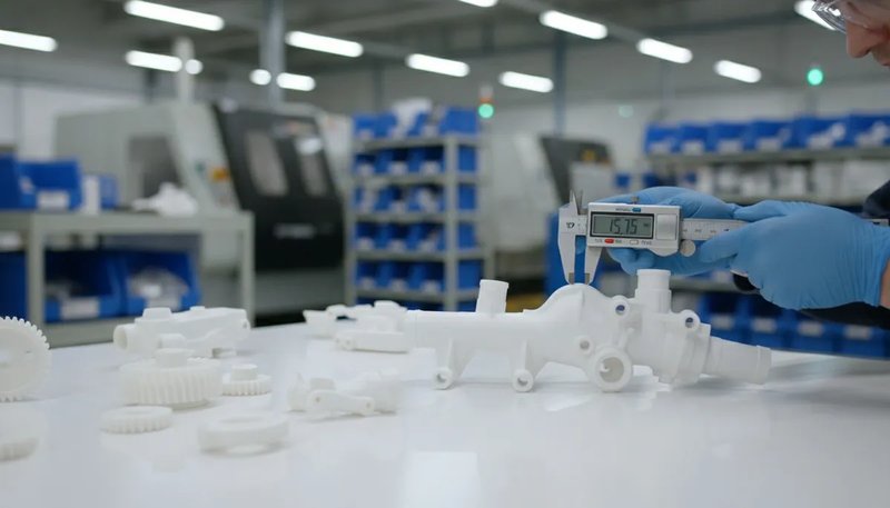
Diagramma che mostra l'unità di iniezione Tempo di ciclo1, and it directly controls your production rate and per-part cost. In our Shanghai factory, we have spent over 20 years fine-tuning cycle times across thousands of molds. This guide breaks down the calculation method so you can estimate, measure, and optimize cycle time on your own projects.
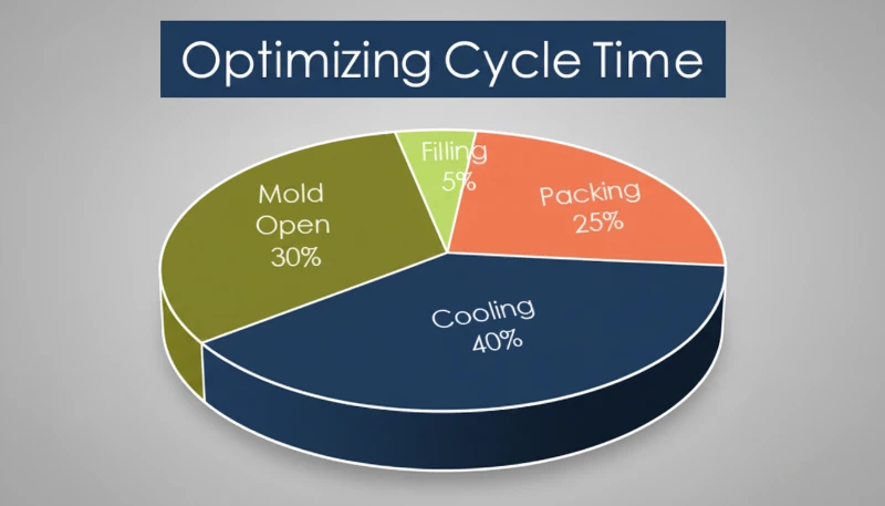
- Cycle time = injection + packing + cooling + ejection + mold open/close
- Cooling typically accounts for 60–70% of total cycle time
- Wall thickness is the single biggest driver of cooling duration
- A 1-second reduction can yield 100,000+ extra parts per year on a multi-cavity mold
- Proper mold cooling design is the most cost-effective optimization
What Is Cycle Time in Injection Molding?
Il tempo di ciclo è il tempo totale trascorso dall'inizio di un colpo di iniezione all'inizio del successivo. Misura la velocità con cui la tua macchina può produrre pezzi — ed è la metrica più importante per stampo a iniezioneing productivity.
Pensala in questo modo: se stai utilizzando uno stampo a 4 cavità con un ciclo di 30 secondi, sono circa 480 pezzi all'ora. Riducilo a 25 secondi e salti a 576 — un aumento della produzione del 20% senza alcun investimento di capitale aggiuntivo. Ecco perché gli ingegneri esperti sono ossessionati da ogni secondo.
The formula is straightforward in concept: t_cycle = t_inject + t_pack + t_cool + t_open + t_eject + t_close. In practice, some phases overlap. Screw recovery2 (plasticizing the next shot) happens during cooling, so you take the longer of t_cool and t_screw_recovery rather than adding both.
Il tempo di ciclo non è una proprietà fissa — cambia con il materiale, la geometria del pezzo, il design dello stampo e le impostazioni della macchina. Un tappo in PP a parete sottile potrebbe ciclare in 5–8 secondi, mentre un alloggiamento in policarbonato a parete spessa potrebbe richiedere 60 secondi o più. Gli ingegneri parlano spesso di “tempo di ciclo ottimale” — il ciclo ripetibile più veloce che produce ancora pezzi conformi a tutte le specifiche di qualità. Spingere troppo velocemente porta a colpi corti, avvallamenti o deriva dimensionale. Spingere troppo lentamente significa sprecare denaro sul tempo macchina.
How Do You Calculate Cycle Time Step by Step?
The cycle time formula is the sum of injection, packing, cooling, and mold operation times. Some phases overlap — for example, screw recovery happens during cooling — so you take the longer duration rather than adding both.
Injection Time (t_inject)
Questo è il tempo necessario per riempire la cavità con plastica fusa. Per la maggior parte dei pezzi, è di 0,5–5 secondi. Puoi stimarlo come: t_iniettare = Peso del pezzo (g) ÷ Velocità di iniezione (g/s). Ad esempio, un pezzo di 50g su una macchina che eroga 100 g/s impiega circa 0,5 secondi per riempirsi. Ma i profili di iniezione reali utilizzano velocità multi-stadio (lento-veloce-lento), quindi il tempo effettivo è leggermente più lungo del minimo teorico.
Packing/Holding Time (t_pack)
After the cavity fills, you maintain pressure to compensate for material shrinkage. This typically runs 1–10 seconds depending on wall thickness and gate freeze-off time. Thin parts freeze fast; thick parts need longer hold. The packing phase ends when the gate solidifies, sealing the cavity.
Cooling Time (t_cool)
This is where most of your cycle lives. For semi-crystalline materials, Tempo di raffreddamento3 is roughly proportional to the square of wall thickness: t_cool ≈ C × (wall thickness)², where C depends on material thermal diffusivity and the temperature difference between melt and mold. For a 3mm wall in ABS, expect 15–25 seconds. For a 5mm wall, it jumps to 40–60 seconds.
Mold Open/Close and Ejection
Mold open and close typically takes 2–10 seconds depending on mold size and press tonnage. Small molds on 80–200T presses run 2–4 seconds; large molds on 500–1000T presses take 6–12 seconds. Ejection time adds 0.5–3 seconds, with automated pickers being faster than manual removal.
Putting It All Together
Ecco un calcolo di esempio per un alloggiamento ABS di medie dimensioni (parete 3mm, 80g, stampo a 4 cavità su pressa 200T): t_inject ≈ 1,5s, t_pack ≈ 3s, t_cool ≈ 20s, t_open + t_eject + t_close ≈ 5s. Tempo di ciclo totale: circa 29,5 secondi. In produzione, abbiamo visto cicli variare da 5 secondi per imballaggi a parete sottile a oltre 90 secondi per parti tecniche spesse.
What Are the Four Phases of an Injection Molding Cycle?
The four phases are injection (filling), packing (holding), cooling, and ejection/reset. Each has a distinct role in part quality and cycle efficiency.
Phase 1 — Injection (Filling)
The screw pushes forward, forcing molten plastic through the runner and gate into the cavity. Speed is critical — too slow and the melt freezes before filling; too fast and you get jetting or flash. Injection time is typically the shortest phase, but it sets the foundation for part quality.
Phase 2 — Packing (Holding)
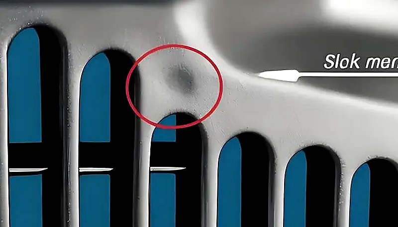
Once the cavity is volumetrically full, the machine switches to holding pressure. This extra pressure packs in additional material to compensate for thermal shrinkage as the part cools. Packing continues until the gate freezes off, sealing the cavity. Getting packing time wrong is a common source of sink marks and voids.
Phase 3 — Cooling
Lo stampo mantiene una temperatura controllata (solitamente 20–80°C a seconda del materiale), sottraendo calore dal pezzo finché non è sufficientemente rigido da essere espulso senza deformazioni. Questa fase è la più lunga — spesso il 60–70% del tempo di ciclo totale. Nel frattempo, la vite si ritrae e plastifica il prossimo colpo, quindi raffreddamento e recupero della vite si sovrappongono.
Phase 4 — Ejection and Reset
The mold opens, the part is ejected (mechanically or by robot), and the mold closes for the next shot. Ejection can be a bottleneck if parts stick or if manual inspection is required. Well-designed ejector systems and proper draft angles keep this phase predictable.
Nella nostra fabbrica di Shanghai, gestiamo 47 macchine per stampaggio a iniezione da 90T a 1850T. Con oltre 20 anni di esperienza produttiva su più di 400 materiali, abbiamo ottimizzato i tempi di ciclo da parti in PP per imballaggio a ciclo rapido a 8 secondi a componenti in PC a parete spessa a 60+ secondi. Ogni macchina registra i dati di ciclo colpo per colpo per il miglioramento continuo.
Why Does Cooling Time Dominate the Cycle?
Cooling is the dominant phase, consuming 60–70% of total cycle time because heat extraction from thick polymer walls takes longer than any other step.
Il polimero fuso entra nella cavità a 200–300°C, e bisogna portarlo a 40–80°C prima che sia sicuro espellerlo. La velocità di trasferimento del calore dipende da diversi fattori.
Wall Thickness — The Big One
Il tempo di raffreddamento scala approssimativamente con il quadrato della sezione più spessa. Un pezzo spesso 4mm richiede circa 1,8× il tempo di raffreddamento di un pezzo da 3mm. Ecco perché le revisioni DFM spingono sempre per uno spessore di parete uniforme minimo.
Material Thermal Conductivity
I materiali amorfi come PC e ABS si raffreddano in modo diverso rispetto a quelli semi-cristallini come PA e POM. I materiali cristallini rilasciano calore latente durante la solidificazione, il che aumenta il tempo di raffreddamento. La scelta del materiale non riguarda solo le prestazioni del pezzo — influisce direttamente sull'economia della produzione.
Mold Temperature and Cooling Channel Design
Lower mold temperature pulls heat faster, but too cold causes residual stress, warpage, or poor surface finish. Well-placed baffle circuits, heat pipes, or conformal cooling channels can cut cooling time by 20–40% compared to basic drilled channels. This is where mold engineering pays for itself.

Cristallizzazione rapida, ottima per componenti elettrici
What Factors Impact Cycle Time Most?
The biggest factors are wall thickness, material thermal properties, mold cooling design, and machine capability — roughly in that order.
Part geometry is the top driver. Thicker walls mean exponentially longer cooling. Complex part geometries with deep ribs, bosses, or varying thickness sections create hot spots that force you to extend the whole cycle for the slowest-cooling area.
Material selection matters because different polymers have different thermal properties. PP and PE cool relatively fast. PC, PPSU, and reinforced nylons need more time. If cycle time is critical and performance allows, switching from PC to ABS can cut cooling by 30–40%.
Mold design is where you win or lose. Key factors include cooling channel placement and flow rate, gate type and location, ejection system reliability, and mold material selection. Beryllium copper inserts conduct heat 3–5× faster than steel and are excellent for hot-spot areas. Machine settings give you incremental gains — higher injection velocity, optimized holding profiles, and faster mold open/close speeds all help, but these are fine-tuning compared to design and mold engineering.
“Il tempo di raffreddamento rappresenta tipicamente il 60–70% del tempo di ciclo totale dello stampaggio a iniezione.”Vero
Correct. Across thousands of production runs in our factory, cooling consistently dominates the cycle. Even on fast-cycling packaging molds, cooling is still the longest single phase.
“Aumentare la velocità di iniezione riduce sempre il tempo di ciclo totale.”Falso
False. Beyond an optimal point, faster injection causes flash, jetting, or air traps that require extended packing and cooling to fix. The net cycle time can actually increase if you push injection speed too far.
How Can You Optimize Cycle Time Without Sacrificing Quality?
Focus on cooling optimization first, then wall thickness reduction, then machine tuning — in that order of impact. Here are the most effective strategies we use in production.
Redesign Cooling Channels
This is the single highest-ROI change. If your mold has basic straight-drilled channels, switching to baffles, bubblers, or spiral channels can reduce cooling time by 15–30%. For high-volume molds, conformal cooling (made possible by metal 3D printing) can achieve 40%+ reductions.
Minimize and Uniformize Wall Thickness
Every 0.5mm reduction in maximum wall thickness can cut cooling time by 10–20%. Keep wall thickness variation under 25% across the part. Work with your design team early — DFM changes are cheap before the mold is cut, expensive after.
Optimize Gate Location and Type
Better gate placement ensures even filling and reduces the need for extended packing time. Hot runner systems with valve gates allow faster cycling because they seal independently of the cooling phase.
Automate Ejection
Robotic pickers or automatic drop systems eliminate the variability of manual part removal. This is especially impactful for cycles under 15 seconds where human response time becomes a bottleneck.
L'avvertenza: qualsiasi ottimizzazione del tempo di ciclo deve essere convalidata con dati di qualità. Se si notano avvallamenti, deriva dimensionale o deformazioni dopo aver ridotto il tempo di ciclo, si è andati troppo oltre. Eseguire sempre uno studio di capacità (Cpk) prima di consolidare un nuovo ciclo. Per una guida sulla scelta del partner di produzione giusto per una produzione ottimizzata, consulta il nostro injection molding sourcing guide.
“Una riduzione del tempo di ciclo di 1 secondo su uno stampo a 4 cavità in funzione 24/7 può produrre oltre 100.000 pezzi aggiuntivi all'anno.”Vero
Correct. Reducing a 30-second cycle to 29 seconds increases output by approximately 145,000 parts per year on a 4-cavity mold running continuously. Even small optimizations compound significantly over high-volume production.
“Utilizzare una temperatura dello stampo più alta migliora sempre la qualità del pezzo e vale l'aumento del tempo di ciclo.”Falso
Falso. Sebbene una temperatura dello stampo più alta possa ridurre le tensioni residue e migliorare la finitura superficiale, prolunga anche il tempo di raffreddamento e può causare un ritiro eccessivo. La temperatura ottimale dello stampo è un equilibrio tra requisiti di qualità ed efficienza del ciclo, non una semplice regola 'più caldo è meglio'.
What Are Typical Cycle Times for Common Materials?
Cycle times vary widely, but here are typical ranges based on real production data for a mid-complexity part with 2–3mm walls. These ranges assume a standard mold with adequate cooling.
| Materiale | Typical Cycle (seconds) | Note chiave |
|---|---|---|
| PP (polipropilene) | 8–25 | Fast cooling, low viscosity — ideal for packaging |
| PE (polietilene) | 8–20 | Similar to PP, good flow characteristics |
| ABS | 15–40 | Moderate cooling, versatile engineering plastic |
| PS (polistirolo) | 10–25 | Fast freezing but brittle — needs careful ejection |
| PC (policarbonato) | 25–60 | High melt temperature, slow cooling |
| PA6 (Nylon 6) | 15–45 | Semi-crystalline, needs thorough cooling |
| PA66 (Nylon 66) | 18–50 | Higher crystallinity than PA6, longer cooling |
| POM (Acetal) | 15–35 | Good thermal properties, fast crystallization |
| TPU | 20–45 | Flexible material, slower ejection required |
| PBT | 15–35 | Fast crystallization, good for electrical parts |
Con canali di raffreddamento conformi ottimizzati, spesso si può lavorare il 20–30% più velocemente di questi intervalli. La conclusione: la scelta del materiale non riguarda solo le prestazioni del pezzo — impatta direttamente la tua economia produttiva attraverso il tempo di ciclo.
How Do You Measure and Monitor Cycle Time in Production?
La misurazione del tempo di ciclo viene eseguita dal timer integrato della macchina, quindi tracciata con software SPC per rilevare precocemente la deriva del processo.
Machine-Level Monitoring
Ogni pressa moderna visualizza il tempo di ciclo in tempo reale. La maggior parte può registrare dati ciclo per ciclo e avvisare gli operatori quando un ciclo supera il limite impostato. Questa è la tua prima linea di difesa — se la macchina indica 32 secondi e hai impostato un obiettivo di 30 secondi, qualcosa richiede attenzione.
SPC Trending and Drift Detection
Track cycle time over hundreds or thousands of shots. A gradual upward trend often indicates a developing problem: fouled cooling channels, worn ejector pins, or material viscosity changes. Catching these early prevents quality issues and unplanned downtime.
Common Causes of Cycle Time Drift
The usual suspects include cooling channel scale buildup (reduces heat transfer), worn hot runner nozzles (slower fill, longer packing), material lot-to-lot variation, hydraulic system degradation on older machines, and ambient temperature changes between seasons.
Our recommendation: set a cycle time upper control limit (UCL) at 5% above your optimized cycle. Any shot exceeding UCL should trigger an investigation. This simple rule catches 80% of developing problems before they produce defective parts. For serious operations, MES (Manufacturing Execution Systems) integrate cycle time data with quality inspection results, letting you correlate cycle variations with part quality in real time.
Domande frequenti
What is the formula for injection molding cycle time?
The basic formula is t_cycle = t_inject + t_pack + t_cool + t_open + t_eject + t_close. However, some phases overlap — particularly cooling and screw recovery. You take the longer of the two rather than adding both. For a quick estimate, cooling time is typically 60–70% of the total, so measuring cooling duration and multiplying by 1.4–1.6 gives a reasonable ballpark. Always validate with actual machine data, as real-world cycle times depend on part geometry, material, and mold design.
How many seconds is a typical injection molding cycle?
Most injection molding cycles fall between 10 and 60 seconds. Thin-wall packaging parts like bottle caps can cycle in 5-8 seconds on optimized high-speed machines. Standard technical parts with 2-3mm walls typically run 15-30 seconds on conventional presses. Thick-wall or high-performance materials like polycarbonate can push to 45-90 seconds due to extended cooling requirements. The specific cycle depends heavily on wall thickness, material thermal properties, mold cooling capacity, and part complexity. If you are consistently running over 60 seconds, investigate cooling optimization.
What is the longest phase in injection molding?
Cooling is almost always the longest phase, consuming 60-70% of total cycle time across most production scenarios. This is because you must extract enough heat from the molten polymer to make the part rigid enough for ejection without deformation. The thermodynamics are unavoidable: cooling time scales roughly with the square of the wall thickness, meaning even small increases in part thickness dramatically extend the total cycle. On thin-wall packaging parts, injection time can be significant, but cooling still dominates the vast majority of production runs.
How does wall thickness affect cycle time?
Wall thickness is the single biggest driver of cycle time because cooling time scales approximately with the square of the wall thickness. Doubling the wall thickness roughly quadruples the cooling time required. For example, a part with a 2mm wall might need 8 seconds of cooling, while the same geometry at 4mm requires 25-30 seconds. This exponential relationship is why design-for-manufacturing reviews always push for minimum uniform wall thickness. Any sections significantly thicker than the rest become the bottleneck for the entire cycle, forcing extended cooling for all cavities.
Can cycle time be reduced without changing the mold?
Yes, you can reduce cycle time without mold changes, but gains are smaller compared to mold-level modifications. Machine-side optimizations include increasing injection velocity, adjusting holding pressure profiles, ensuring optimal cooling water flow rate and temperature, and switching to a faster-cycling material grade. These adjustments typically yield 5-15% improvements in cycle time. For larger gains of 20-40% or more, you generally need mold modifications such as improved cooling channels, beryllium copper inserts in hot-spot areas, or gate redesign for more efficient filling.
What is the difference between cycle time and lead time in injection molding?
Il tempo di ciclo misura la velocità di produzione — il tempo per un ciclo macchina da un colpo al successivo. Il lead time è il tempo totale dal posizionamento dell'ordine alla consegna, inclusa fabbricazione dello stampo, approvvigionamento materiali, pianificazione produzione, controllo qualità e spedizione. Un pezzo con un tempo di ciclo di 20 secondi potrebbe avere un lead time di 4–6 settimane per un nuovo stampo, o 3–5 giorni per una produzione ripetuta. Comprendere entrambe le metriche è essenziale per la pianificazione del progetto — tempi di ciclo rapidi non aiutano se lo stampo non è pronto.
How do you calculate cooling time in injection molding?
A simplified cooling time estimate uses the formula t_cool = (thickness squared times thermal_factor) divided by thermal_diffusivity, where the thermal factor depends on the temperature difference between melt temperature and mold temperature. In practice, most engineers rely on empirical production data or mold simulation software like Moldflow because real part geometries are too complex for accurate hand calculations. As a practical rule of thumb, for a 3mm wall in amorphous material like ABS, expect 15-25 seconds. For the same thickness in semi-crystalline nylon, add 20-30% more cooling time.
Why does my cycle time vary shot to shot?
Minor cycle time variation of plus or minus 0.5-1 second is completely normal and results from slight differences in material feeding consistency, screw position repeatability, and hydraulic system response. Larger variations exceeding 2 seconds usually indicate a real problem: inconsistent material drying, clogged or scaled cooling channels, a worn check ring causing shot-size variation, or faulty temperature sensors. If you observe a gradual upward trend over hundreds of shots, check cooling water flow rate first because mineral scale buildup inside channels is the most common cause of slow cycle time drift.
Ready to Optimize Your Injection Molding Cycle Time?
Il team di ingegneria di ZetarMold ha oltre 20 anni di esperienza nell'ottimizzazione dei cicli produttivi su 400+ materiali. Per una panoramica dettagliata delle capacità, consulta il nostro complete guide to injection molding. From mold design review to production tuning, we help you achieve the fastest cycle without compromising quality. Request a free quote for your next project.
-
Cycle time: Cycle time refers to the total elapsed time from the start of one production cycle to the start of the next in a repeating manufacturing process. ↩
-
Screw recovery: Screw recovery refers to the phase where the injection screw rotates to plasticize and accumulate the next shot of material while the previous part cools in the mold. ↩
-
Tempo di raffreddamento: Cooling time refers to the duration required to reduce the temperature of a molded polymer from its melt temperature to a safe ejection temperature within the mold cavity. ↩


