 Skip to content


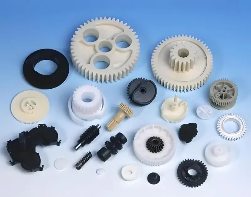
Injection molded parts are key components in various industries, offering precision, cost-effectiveness, and scalability in mass production.
Injection molded parts are created by injecting molten material into a mold. They are used in automotive, electronics, medical devices, and consumer goods, offering precise, repeatable shapes and high-volume production.
To optimize injection molding processes, it’s essential to understand material selection, mold design, and production techniques. Delve deeper to learn how these factors impact your part’s performance and cost efficiency.
Injection molded parts are ideal for mass production.True
Injection molding allows high-volume, cost-effective production of identical parts, making it ideal for industries requiring mass quantities.
Injection molded parts are always cheaper than other manufacturing methods.False
While injection molding is cost-effective at scale, the upfront mold design and production setup costs can be high for smaller runs.
What are the Injection Molding Process Parameters?
Injection molding process parameters are critical in determining the quality, efficiency, and consistency of molded products. Understanding these parameters is essential for optimizing production.
Key injection molding parameters include temperature, pressure, injection speed, cooling time, and mold design. Proper control of these factors ensures high-quality parts with minimal defects and improved production efficiency.

Barrel Temperature
The melt temperature is very important, and the injection cylinder temperature used is only a guide. The melt temperature can be measured at the nozzle or measured using the air injection method1
The temperature setting of the injection cylinder depends on the melt temperature, screw speed, back pressure2, shot volume and injection molding cycle3.
If you don’t have experience processing a particular grade of plastic, start with the lowest setting. The injection cylinder is divided into zones for control, but they’re not all set to the same temperature.
If you’re running a long job or running hot, set the temperature of the first zone lower to keep the plastic from melting and squirting out too soon. Make sure the hydraulic oil, hopper closer, mold, and injection cylinder are at the right temperature before you start to mold.
Melt Temperature
The melt temperature is a big deal for how the melt flows. Plastic doesn’t have a specific melting point, so the so-called melting point is a temperature range when it’s melted. Different plastics have different structures and compositions, so they flow differently.
Temperature has a more obvious effect on rigid molecular chains, such as PC, PPS4, etc., while temperature has less of an effect on flexible molecular chains, such as PA, PP, PE, etc.
The fluidity does not change much with temperature, so the reasonable injection molding temperature should be adjusted according to different materials.
Mold Temperature
Some plastic materials need a higher mold temperature because they have a high crystallization temperature and slow crystallization speed. Some need a higher or lower temperature because they need to control size and deformation or demolding.
For example, PC generally needs more than 60 degrees, while PPS sometimes needs a mold temperature of more than 160 degrees to make it look better and flow better. So, mold temperature is very important for improving the appearance, deformation, size, and rubber mold of the product.
Injection Pressure
The resistance that the melt has to overcome to advance affects the size, weight, and deformation of the product. Different plastic products require different injection pressures.
For materials like PA and PP, increasing the pressure will greatly improve their fluidity. The injection pressure determines the density of the product, that is, the glossiness of the appearance. It has no fixed value, and the more difficult it is to fill the mold, the greater the pressure of the injection molded part.
Controlling temperature and pressure improves product quality.True
Maintaining optimal temperature and pressure ensures consistent material flow and part formation, minimizing defects and ensuring high-quality parts.
Increasing injection speed always improves cycle time.False
While faster injection speeds can reduce cycle times, they may also increase the risk of defects like warping or incomplete filling if not properly controlled.
What are the Design Principles of Injection Molded Parts?
The design principles of injection molded parts ensure optimal functionality, cost-effectiveness, and manufacturability, essential for achieving high-quality production.
Key principles for designing injection molded parts include part geometry, material selection, wall thickness uniformity, draft angles, and minimizing undercuts. These factors help ensure the part’s durability, manufacturability, and cost-efficiency in the injection molding process.

Wall Thickness Determination for Injection Molded Parts
The wall thickness of your injection molded product should be as even as possible, and you should try to keep the thickness consistent throughout. The minimum wall thickness for the entire injection molded product should be at least 0.6mm, or else it will stick to the mold and be hard to get out.
Injection molded products are divided into three categories: large, medium, and small. Small products are those with a size below 100, and their general wall thickness ranges from 0.6mm to 1.0mm.
Medium products are those with a size between 100 and 200, and their general wall thickness ranges from 1.2mm to 2.0mm. Large products are those with a size above 200, and their general wall thickness is more than 2mm.
When the size of an injection molded product is greater than 200mm, the product wall thickness is calculated as follows: 2 + (X – 200) / 100. For example, if the product size is 300mm, the product wall thickness is calculated as 2 + (300 – 200) / 100 = 3mm. Therefore, the product wall thickness is 3mm.
Thickness Design Example
Injection molded parts are plastics that flow into the mold at high temperature and are formed into a certain shape. If the wall thickness of the injection molded parts is too thick.
While the strength is increased, using too much material will increase the cost and make injection molding more difficult. It will take longer to cool and you will need to use more pressure to inject it.
In today\’s world, where businesses are all about efficiency, extending the cooling time is a big deal. It affects production efficiency because once you make injection molded parts, you make thousands, tens of thousands, or even millions of them.
If the wall thickness is too thick, you get bubbles and shrinkage. If the wall thickness is too thin, it’s hard to get the part out of the mold, and the plastic doesn’t have good strength because it has a lot of flow resistance in the mold cavity.
Injection molded parts are also called plastic parts. You want to make the wall thickness as uniform as possible, as long as you can keep the wall thickness.
Otherwise, when you mold the plastic parts and hold them under pressure, and then cool them down, you get dents, you get deformation, you get bubbles, and all kinds of stuff.

Key Points of Demolding Angle Design
The touch angle, also known as the demolding angle, is not fixed. It is determined by experience and the depth and size of the product. For 99% of plastic products, there is a certain angle between the inner and outer walls to facilitate the removal of the plastic product from the mold. The draft angle is generally between 0.5° and 3°.
The inner wall draft of the screw is usually 0.5°. The outer surface draft depends on the size of the product. Screws are generally small and medium-sized products, and the draft angle is usually 1°.
The specific draft should pay attention to the following points: generally, the inner small end face is used as the standard, the draft angle is outward, and the outer large end face is used as the standard.
Plastic part size The demolding angle (touch angle) should be smaller. For high precision plastic parts, the demolding angle (touch angle) should be smaller. To prevent mold scratches and smooth demolding, the demolding angle (touch angle) should be larger. The angle is generally 3°.
For plastic parts with a lot of shrinkage, the angle at which the part is removed from the mold (the touch angle) should be bigger, like 2°-3°.
Reinforcement Rib Design
The reinforcement rib seems to strengthen the strength of plastic parts and prevent deformation. Thickening the wall thickness can also strengthen the strength and rigidity of plastic parts, but adding Thick wall thickness is overall thickening, which increases material cost and holding time, and greatly reduces production efficiency.
So, in order to strengthen the strength of plastic parts and prevent deformation, it is better to increase the number of reinforcing ribs rather than increase the wall thickness.
Key Points of Reinforcing Ribs
The thickness of the reinforcing ribs (A) is generally 2/3 to 1/2 of the wall thickness (T) of the plastic part. Assuming the wall thickness (T) of the plastic part is 1mm, the thickness of the reinforcing ribs (A) is 0.5mm to 0.67mm.
If the distance between the reinforcing ribs is greater than 8T, the distance between two reinforcing ribs is at least 8mm, and the height of the reinforcing ribs (C) is less than 3T, then the rib height is less than 3mm, which is only a theoretical value. The actual situation may vary.
The Role and Design of the Stopper
The stopper prevents the plastic parts from being installed upside down. The stopper is similar to the art line, which plays a role in aesthetics.
Common Buckles, Buckle Functions and Buckle Designs
There are many types of buckles, such as trapezoidal buckles and right-angle buckles. The purpose of the buckle is to connect two or more separate plastic parts together. The angle of the buckle is usually between 30 and 45 degrees. In theory, the smaller the angle, the easier it is to buckle. The principle of the buckle is to use the deformation of the plastic parts to make two plastic parts or a plastic part and a metal part buckle together.
Here are some points to note about the snap design. Choose a trapezoidal snap or a right-angle snap based on the actual situation. When the buckle amount is greater than 0.6mm, it is a dead buckle, and less than 0.6mm is a live buckle. The snap mainly controls three directions so that it will not move, namely X, Y, and Z, with a gap of 0.1-0.15mm.
Thicker walls in injection molded parts improve durability.False
Thicker walls can lead to uneven cooling, higher costs, and longer cycle times, which might actually reduce durability in some cases.
Draft angles are necessary for easy part removal from molds.True
Draft angles allow the part to be removed from the mold without damage, improving both the quality and efficiency of production.
What are the Design Techniques for Injection Molded Parts?
Design techniques for injection molded parts are essential for optimizing product quality and production efficiency, influencing factors like material flow, mold cavity design, and part functionality.
Key design techniques for injection molded parts include optimizing wall thickness, using draft angles, and ensuring proper venting. These methods help reduce cycle times, prevent defects, and improve part strength, making the manufacturing process more efficient.
Best Uniformity
The best fluidity is achieved by maintaining a constant wall thickness5 throughout the part. The nominal wall thickness should be between 2-3mm. For traditional plastic injection molding processes, the recommended minimum value is 1mm and the maximum value is 4mm.
Smoothness is Better Than Sharpness
Use radius as much as possible and avoid sharp transitions between wall sections.
Draft Angle is Your Friend and Enemy
Adding draft angles to the surface of a part helps release it from the tool, but it can bring design challenges, especially for mating parts. The recommended minimum draft angle is 1 degree on a non-textured core and at least 3 degrees on a textured cavity surface.
Avoid Zero-Draft Surfaces Unless Necessary
If you do need a zero-draft area to ensure proper part fit and tolerances, try to minimize it to only a portion of the face, not the entire surface.
Simpler is Better
Avoid undercuts (areas that can’t be made with the simple open/closed direction of the tool). When simple methods don’t work, lifters and slides allow for undercut features in the primary pull direction. If so, leave at least 2 to 3 times the feature width to allow for lifter or slide movement.
Thick-To-Light Transitions
Parts will mold better if the plastic moves from a larger wall thickness to a smaller wall thickness starting at the gate (where the plastic first flows in to fill the part). Dimpling (localized surface depressions in a part due to slower cooling of thicker section plastic) is not good.
To reduce or eliminate the visibility of cosmetic surface blemishes, be sure to follow some recommended guidelines: Avoid gates, ribs, screw bosses, etc. on the back of important decorative surfaces; Rib height should be 3 times the wall thickness or less; Rib base should be 60% of the wall thickness or less.
Datum Definition Areas
Use datums to establish part interfaces and interactions with the entire system. Using datum structures that match the design intent of the assembly can mean the difference between a product that works or not.
Review is Important
Pay attention to DFM (Design for manufacturing process) reports because they tell you what the moldmaker thinks about your design, especially things like where the ejector pins are (which might not match your planned design changes), where the gate is (which might make the part look bad), and where the parting line is (which might mess up how the part works with other parts). Use inspection reports to check your design. Here’s an example of a DFM report:
Prototype Early And Often
Current prototyping methods (including 3D printing) allow for early testing of design concepts, and you can model partial and/or entire parts before you build expensive tools.
Optimizing wall thickness improves part strength and reduces defects.True
Consistent wall thickness ensures even material flow, preventing weak spots and reducing chances of defects like warping or sink marks.
Increasing wall thickness always improves part durability.False
While thicker walls can enhance durability, excessive thickness can lead to longer cooling times, higher material costs, and potential warping issues.
What are the Key Points in Injection Molded Parts Design?
Effective design of injection molded parts is essential for optimizing performance, reducing costs, and ensuring high-quality production. Understanding key principles can significantly enhance your molding process.
Key points in injection molded parts design include material selection, wall thickness, draft angles, and parting lines. Proper design minimizes defects, reduces cycle times, and ensures cost-effective manufacturing.

Mold Opening Direction And Parting Line
When designing an injection molded product, the first thing you need to do is figure out which way the mold is going to open and where the parting line is going to be. This way, you can minimize the number of cores you have to pull and get rid of any cosmetic issues caused by the parting line.
Once you figure out which way the mold is going to open, you design the product’s ribs, snaps, bumps, and other features to go along with the mold opening direction as much as possible. This way you don’t have to pull cores, you reduce the parting line, and you make the mold last longer.
For example: The mold opening direction of the bumper is usually the x-axis of the body coordinate. If the mold opening direction is designed to be inconsistent with the x-axis, the angle must be indicated in the product drawing.
After determining the mold opening direction, select the appropriate parting line to improve the appearance and performance.
Demolding Slope
To avoid product burrs, the appropriate demolding slope should be used. The demolding slope of the smooth surface should be greater than 0.5 degrees, the surface of the fine leather grain should be greater than 1 degree, and the surface of the rough leather grain should be greater than 1.5 degrees. The appropriate demolding slope can avoid product top damage.
When designing deep cavity structure products, the outer surface slope is required to be smaller than the inner surface slope to ensure that the mold core is not offset during injection molding, obtain uniform product wall thickness, and ensure the material density strength of the product opening.
Product Wall Thickness
Different plastics have a certain range of wall thickness, usually 0.5 to 4mm. When the wall thickness exceeds 4mm, it will cause too long cooling time and shrinkage problems. The product structure should be changed.
If your wall thickness isn’t even, you’ll get shrinkage on the surface. If your wall thickness isn’t even, you’ll get pores and weld marks.
Reinforcement Ribs
Using reinforcement ribs in a smart way can make your parts stronger and less likely to warp. The thickness of the ribs should be less than one-third the thickness of the wall, or you’ll get sink marks. The angle of the ribs should be greater than 1.5 degrees to avoid a sharp edge.
Fillet
If the fillet is too small, it will cause stress concentration of the product, resulting in product cracking. If the fillet is too small, it will cause stress concentration of the mold cavity, resulting in cavity cracking.
Setting a reasonable fillet can also improve the processing technology of the mold, such as the cavity can be directly processed by R cutter milling, avoiding inefficient electrical processing.
Different fillets can cause parting lines to move, so choose different fillets or corner clearances based on the actual situation.
Holes
The hole shape should be as simple as possible, generally round. The hole should be oriented in the direction of mold opening to avoid undercuts. When the hole has an aspect ratio greater than 2, a draft angle should be added.
In this case, the hole diameter should be calculated based on the minor diameter (the largest physical size). The aspect ratio of blind holes is generally not more than 4.

The distance between the hole and the edge of the product is usually larger than the hole diameter size. The core-pulling mechanism of injection mold and avoidance.
When the plastic part can’t be demolded smoothly in the mold opening direction, you need to design a core-pulling mechanism.
The core-pulling mechanism can create intricate product designs, but it can also lead to issues like stitch lines and shrinkage, which can drive up mold costs and reduce mold life.
When you design injection molded products, try to avoid core-pulling6 structures unless you have special requirements. For example, change the direction of the hole axis and the rib to the mold opening direction, and penetrate the cavity core.
Integrated Hinge
By using the toughness of PP material, we can design the hinge to be integrated with the product.
The size of the film used as a hinge should be less than 0.5mm and be uniform.When you’re putting in a concealed hinge, you can only put the door on one side of the hinge.
Inserts
Adding inserts to injection molded products can enhance local strength, hardness, dimensional accuracy, and create small threaded holes (axles) to meet various special requirements.
However, it will increase the cost of the product. Inserts are usually made of copper, but can also be made of other metals or plastic parts. The part of the insert that is embedded in the plastic should be designed with a structure that prevents rotation and pull-out, such as knurling, holes, bending, flattening, shoulders, etc.
The plastic around the insert should be appropriately thickened to prevent stress cracking of the plastic part. When designing the insert, the method of positioning the insert in the mold (holes, pins, magnetism, etc.) should be fully considered.
Logo
The product logo is usually placed on the flatter part of the product, and it is convex. The logo is placed on the part where the normal and the mold opening direction can be consistent to avoid stress.
Injection molded parts precision: Because the shrinkage rate of injection molded parts is uneven and uncertain, the precision of injection molded parts is much lower than that of metal parts.
According to the standard (OSJ1372-1978), the deformation of injection molded parts should be selected to determine the appropriate tolerance requirements; improve the rigidity of the injection molded product structure and reduce deformation. Try to avoid flat structure, reasonably set flange, concave and convex structure. Set reasonable reinforcement ribs.
Gas-Assisted Injection Molding
Gas-assisted injection molding can make products more rigid and less likely to warp. Gas-assisted injection molding can prevent shrinkage. Gas-assisted injection molding can save material and speed up cooling.
Welding (Hot Plate Welding, Ultrasonic Welding, Vibration Welding)
Welding can make the connection stronger. Welding can make the design simpler.
Think about the trade-off between process and product performance.
When you design injection molding products, you have to consider the contradiction between product appearance, performance and process comprehensively.
Sometimes, you have to sacrifice some processability to get a good appearance or performance. When the structural design can\’t avoid injection molding defects, try to make the defects occur in the hidden parts of the product.
Optimizing wall thickness improves part strength and reduces material waste.True
Consistent and optimal wall thickness ensures uniform cooling and reduces material usage, enhancing part strength and reducing costs.
Draft angles are not necessary for every injection molded part.False
Draft angles are essential for easy part removal from the mold, preventing damage and reducing production time.
What are the Common Defects of Injection Molded Parts?
Injection molded parts can experience various defects, which can compromise both functionality and aesthetics. Recognizing and addressing these issues ensures higher product quality and efficiency in production.
Common injection molding defects include warping, sink marks, short shots, and flash. These issues arise from factors like improper temperature, pressure, or material choice, affecting part quality and functionality.
Short Shot
Short shot is when the mold cavity doesn’t fill up all the way.
-
Causes of short shot:Mold temperature, material temperature, or injection pressure and speed are too low, material isn’t melted evenly, there’s not enough venting, material doesn’t flow well, the part is too thin or the gate is too small, or the polymer melt solidifies too soon because of a bad design.
-
Short shot solution:Quick fix: Use a material with better flowability, like toolox44. Fill the thick wall before filling the thin wall to avoid hold-up, increase the number of gates and runner size, reduce the process and flow resistance.
-
Short shot solution:Set the exhaust position and size properly to avoid poor exhaust, check if the check valve and the barrel inner wall are severely worn, check if there is material in the feed port or if it is bridged.
-
Short shot solution:Boost the injection pressure and injection speed, increase the shear heat, increase the injection volume, increase the barrel temperature and mold temperature.
Brittleness
When plastic parts are brittle, it means they crack or break easily in certain areas.
-
Causes of Brittleness:Reasons for brittleness include: improper drying conditions; excessive use of recycled materials; incorrect injection temperature settings; improper gate and runner system settings; and low melt strength.
-
Causes of Brittleness:When plastic parts are brittle, it means they crack or break easily in certain areas. Reasons for brittleness include: improper drying conditions; excessive use of recycled materials; incorrect injection temperature settings; improper gate and runner system settings; and low melt strength.
-
Solution for brittleness: Set the drying conditions properly before injection molding, reduce the use of recycled materials, and increase the proportion of new materials.
-
Solution for brittleness:Choose high-strength plastics. Reduce the temperature of the barrel and nozzle, reduce the back pressure, screw speed and injection speed, increase the material temperature, increase the injection pressure, and improve the strength of the melt mark.
Scorch
Scorch marks happen when the gas in the cavity can’t get out fast enough, so it burns black at the end of the flow.
-
Causes of burning:air in the cavity can’t get out fast enough, melt temperature too high; screw speed too fast; runner system designed wrong.
-
Solutions for burning: add exhaust system in places where poor exhaust is likely to occur, increase the size of runner system, reduce injection pressure and speed, reduce barrel temperature, and check whether the heater and thermocouple are working properly.
Delamination And Peeling
When a part delaminates or peels, it means that the surface of the part can be peeled off layer by layer.
-
cause delamination and peeling: mixing with other polymers that don’t get along, using too much release agent when you make the part, the resin temperature not being the same all the time, too much water, and sharp angles in the gates and runners.
-
Fixes for delamination and peeling:don’t mix incompatible impurities or contaminated recycled materials into raw materials, chamfer all runners or gates with sharp angles, increase barrel and mold temperature, properly dry the material before molding, and don’t use too much release agent.
Jet Marks
Jet marks (jetting): Jet marks are caused by melt flow that is too fast, and they usually look like snakes.
-
cause of jet marks:the gate is too small, the product surface has a large cross-sectional area, and the filling speed is too fast.
-
Jet marks solutions: increase gate size, change side gate to lap gate, add material stopper pin in front of gate, reduce filling speed just after passing gate.
Flow Marks
- Jet marks solutions: Flow marks are those wavy molding defects on the surface of your product. They’re those frog jump marks caused by the molten plastic flowing too slow.
-
cause of flow marks: Your product’s structure is causing too much acceleration during the filling flow.
-
Flow marks solutions: increase the size of the cold well in the runner, increase the size of the runner and gate, shorten the size of the main runner or use a hot runner, increase the injection speed, increase the injection pressure and the holding pressure.
Silver Streaks
Silver streaks are when water, air, or carbonized stuff spreads out on the part’s surface in the direction of flow.
-
cause of silver streaks:: too much water in the raw materials, air trapped in the raw materials, the plastic breaking down: stuff getting in the material; the barrel is too hot; not enough plastic going in.
-
Silver streak solutions:Choose the right plastic injection molding machine and plastic injection mold. When changing materials, clean the old materials out of the barrel completely. Improve the venting system. Lower the melt temperature, injection pressure, or injection speed.
-
Silver streak solutions:Dry the raw materials according to the data provided by the raw material supplier before injection molding. Check if there are enough vents.
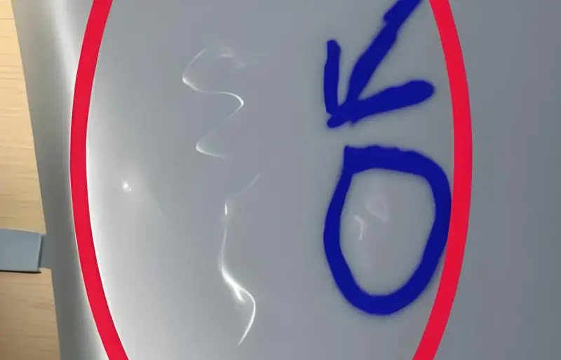
Dent
Dent is when the surface of the part caves in at the wall thickness.
-
cause of Dents:: Injection pressure or holding pressure is too low,Holding time or cooling time is too short,Melt temperature or mold temperature is too high,Part structure design is bad
-
Dent solutions:corrugate the dent-prone surface, reduce part wall thickness, minimize thickness-to-diameter ratio, control adjacent wall thickness ratio at 1.5~2, make transition as smooth as possible, redesign rib thickness, countersunk holes and corner ribs .
-
Dent solutions:Generally recommend their thickness to be 40-80% of basic wall thickness, increase injection pressure and holding pressure, increase gate size or change gate position.
Flash
Flash is when there’s extra plastic on the mold parting surface or ejector pin.
-
Reasons for flash:not enough clamping force, mold problems, bad molding conditions, exhaust system not right
-
flash solutions:Quick fix: Make sure the mold is closed tight when you clamp it. Check the size of the hole where the air comes out. Clean the mold. Use a machine that’s big enough.
-
flash solutions:Make the machine take longer to shoot the plastic in. Make the machine shoot the plastic in slower. Make the machine cooler. Make the machine shoot the plastic in softer. Make the machine hold the plastic in softer.
Warping occurs due to uneven cooling in injection molding.True
Warping happens when parts cool unevenly, causing them to bend or twist, often due to improper mold design or cooling settings.
Short shots only occur with low-quality materials.False
Short shots can happen with both high and low-quality materials, typically caused by insufficient injection pressure or an improperly set mold.
Conclusion
plastic injection molding process refers to the process of making semi-finished products of a certain shape from molten raw materials through operations such as pressurization, injection, cooling, and separation.The choice of plastic parts is mainly determined by the type of plastic ( thermoplastic7or thermosetting), the starting form, and the shape and size of the product.
Injection molding is generally made by compression molding, transfer molding, and injection molding. Lamination, compression molding and thermoforming are to shape plastics on a plane.
Zetar Mold is a professional injection molder that performs plastic injection molding work and has a large number of plastic injection molds. If you have any needs, please contact Zetar Mold.
-
Learn about Secondary air injection : Secondary air injection is injected into the exhaust stream to allow for a fuller secondary combustion of exhaust gases. ↩
-
Learn about What is Back Pressure in Injection Molding & Why is It Important? Back Pressure is resistance applied to the back of the screw during plasticizing (screw recovery). ↩
-
Learn about Molding 101: The Injection Molding Cycle : The injection molding cycle includes The Mold Closes, The Mold Clamps, Sprue Break, First Stage Injection, Pack and Hold, Cooling, Screw Rotatio, The Mold Reopens, The Part Ejects. ↩
-
Learn about PPS Injection Molding Guide(2025) : PPS is a crystalline new high-performance thermoplastic resin with phenyl sulfide groups in its molecular chain. ↩
-
Learn about Wall Thickness for Injection Molding Best Practices : Wall thickness in injection molded parts generally ranges from 1 to 5 mm. ↩
-
Learn about Everything you need to know about core pull injection molding : Core pulling involves the use of a moving plate that helps shape the molten plastic as it is injected into the mold. ↩
-
Learn about Thermoplastic : Most thermoplastics have a high molecular weight. ↩


