 Skip to content

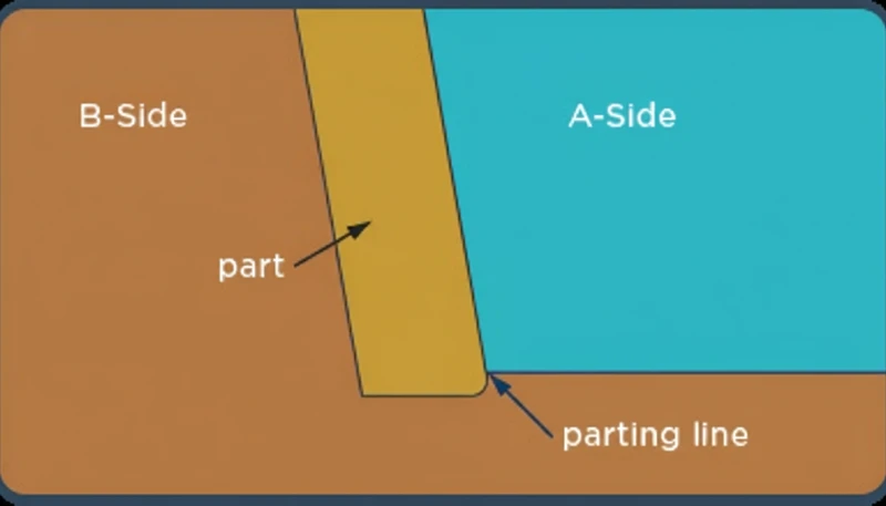
Determining the parting line is critical for successful mold design1, as it defines the point where two mold halves meet and separate during injection molding2.
The parting line is typically determined by design, material flow, and ease of removal. It affects part quality and mold complexity. Ideally, it should be placed to minimize visible seams and enhance functionality.
Understanding how to position the parting line effectively ensures better part quality and mold efficiency. Learn how design choices influence parting line placement and improve molding outcomes.
- The parting line defines where mold halves separate and directly impacts part quality.
- Parting line selection must balance product aesthetics, demolding ease, and mold manufacturability.
- Flat, curved, and composite parting lines each suit different part geometries.
- Proper parting surface design reduces flash, simplifies ejection, and extends mold life.
“The parting line position significantly affects part quality and mold longevity.”True
Correct: the parting line determines flash location, ejection direction, and surface finish quality.
“The parting line has no impact on mold efficiency.”False
The location and design of the parting line play a key role in molding efficiency, as it influences both the ease of mold opening and the final part quality.
What is the Concept of a Parting Surface?
A parting surface is the boundary plane where the two halves of an injection mold meet, separate, and close during each cycle. It defines the mold opening direction and determines how the part releases.
A parting surface plays a vital role in injection molding, where it forms the boundary between the mold halves, enabling easy separation of molded parts. The clamping unit holds both halves together under high pressure, and the parting surface is a key interface that determines how the mold opens and closes during each cycle. Understanding this concept ensures smooth production and consistent part quality.
The parting surface in injection molding is the line or plane where the mold halves meet. It affects parting line quality and ease of mold opening. Correct design ensures efficient mold release and part integrity.
Definition of the Parting Line Injection Molding
The mold parting line is the part of the mold where the moving mold (also known as the moving part of the mold) and the fixed mold (also known as the fixed part of the mold) contact. It is the interface where the mold halves open and close. The parting line determines the injection molding process, appearance, and final product size.
The reasonable design of the parting line does help improve product quality, inhibit mold wear, and extend the service life of the mold. In some designs, a vertical parting line is used to accommodate specific product shapes or mold structures.
Functions of the Parting Line
The parting line serves several important functions in an injection mold:
Mold Opening and Closing: The parting line is the interface where the mold opens and closes, with the moving mold and fixed mold separating and joining along the parting line. The mold opening direction is defined by this interface.
Product Ejection: The molded product is removed from the mold through the parting line.
Layout of the Gating and Venting Systems: The position of the mold line will affect the design of the mold for pouring and venting.
mold processing3 and Manufacturing: An adequate design of the parting line contributes to the simplification of mold processing and lower manufacturing costs.
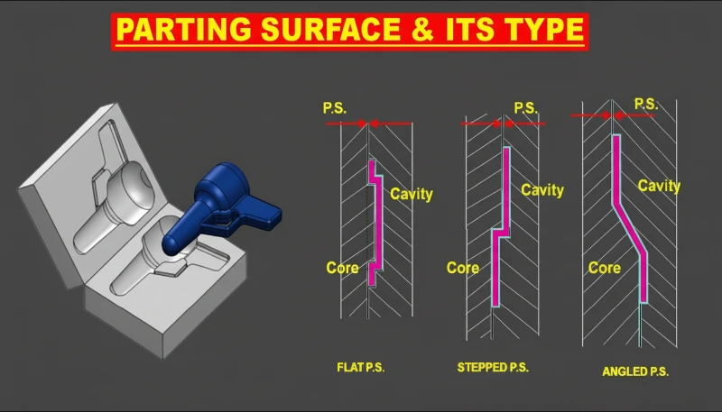
Types of Parting Lines
Parting lines can be classified into the following types:
Flat Parting Line: Applicable for different kinds of products that are rather simple in structure and have smooth surface.
Curved Parting Line: Appropriate where the product has intricate detailed and generally curved surfaces.
Composite Parting Line: Consisting of multiple flat or curved surfaces, suitable for products with complex shapes and multiple angles.
“The parting surface is essential for mold separation.”True
The parting surface ensures that the mold opens and closes smoothly, allowing for easy removal of the part.
“Parting surfaces can be designed anywhere on a part.”False
Parting surfaces are carefully designed based on part geometry to ensure proper mold alignment and minimize defects, not just placed arbitrarily.
What are the Basic Principles for Selecting a Parting Surface?
Selecting the right parting surface is crucial for mold design. It impacts the ease of mold release, part quality, and overall manufacturing efficiency.
A parting surface should be chosen based on part geometry, ease of assembly, and minimizing undercuts. Proper selection ensures better mold function, part ejection, and a smoother production process.
Ensuring Product Quality
The main criterion for the choice of the parting line is the appearance quality and dimensional accuracy of the product. Many times the wall thickness of a finished part is only a few millimeters or maybe 1/8-inch, and poor parting line quality can affect how well the parts are formed together.
The parting line should be steered clear of the primary appearance surfaces of the product to avoid poor parting line quality affecting the appearance. The position of the parting line should avoid causing product deformation or affecting dimensional accuracy.
Facilitating Demolding
The position of the parting line must allow the easy removal of the product without applying high tensile or compressive forces on the product that can cause deformation or damage of the product.
Facilitating Mold Processing
The selection of the parting line should take into account the processing and manufacturing of the mold, opting for positions that are easy to process and have lower costs. It can be noted that elaborate designs that are made on the parting line can cause difficulties in the processing of the mold and also adds to its cost.
Facilitating Gating and Venting System Design
The location of parting line should in some ways help in the positioning of the gating and venting system, to enable the flow of the molten plastic to the mold cavity without bringing in air which leads to defect like bubblesor burn marks.
Meeting Mechanical Requirements
The parting line locations should provide adequate strength and also sturdiness of the mold that is utilized in operation so as to minimize on deformation or damages caused by parting line positioning.
“Parting surface selection impacts part ejection and mold efficiency.”True
The right parting surface minimizes undercuts, ensuring easier ejection and smoother mold functionality.
“Parting surfaces always need to be at the center of the part.”False
While the center is often ideal, the parting surface can vary depending on geometry and the need to avoid complex undercuts.
What are the Factors that Affect the Selection of a Parting Surface?
Part geometry, mold structure, and demolding method are the three primary factors that determine parting surface selection. These factors interact with each other and must be evaluated together during DFM review. If you are comparing vendors, our injection molding supplier sourcing guide covers RFQ prep and qualification.
Product Structure and Shape
The structure and shape of the product are the main basis for selecting the parting line. Whether you are designing a prototype mold or a high-volume production tool, the same principles apply. In the case of injection molded parts with a complicated shape, various aspects must be taken into account, namely draft angles in all planes, flatness of the parting line, and its effect on appearance.
Parting Line Location: Parting line is the operational line of the product formed because of the existence of the parting line. When choosing the parting line, it should not be situated in a place that will influence the appearance quality of the product severely.
Molding Process
Different molding processes have different requirements for parting lines. For example, while practicing injection molding, the parting line position must be chosen in a way that would assist the filling and cooling of the molten plastic while on the other hand die casting demands parting line position that would be helpful in designing the gating and venting systems.
Injection Molding Process: In the case of the injection molding technique, the position of the parting line should favor the More likely fill of the molten plastic and this should not hinder the flow of the plastic hence preventing the formation of features such as bubbles or voids.
Die Casting Process: Within die casting, the position of the parting line should facilitate the layout of the venting system so that the air within the die merchandise cavity can be expelled efficiently without causing issues of porosity or burn marks.
Mold Structure
Another aspect, which determines the selection of the parting plane, is the structure of the mold. For instance, in the case of three-plate molds, stack molds, and other such structures, the selection of the parting line should depend on the mold’s parting as well as opening methods.
Three-Plate Mold: Three-plate molds have the two parting line while it has multiple gate points, which are suitable when producing intricate products. The parting line should however be chosen in relation to the gating positions, and in accordance with the method used in the ejection of the product.
Stack Mold: For high volume production, stack molds are appropriate, the selected parting line should coincide with the structure and the shape of the product so that all layers open at the same time and facilitate the ejection of the product.
Demolding Method
From the selection of the ejection method in mold design, it will impact the parting line direction as well. For instance, if mechanical, pneumatic, hydraulic ejection is needed the parting line must be selected so as to accommodate the necessary position of the ejection device.
Mechanical Demolding: Mechanical demolding is suitable for products with relatively simple designs and small drafts. The parting line should be selected in a position that allows the introduction of mechanical demolding equipment.
Pneumatic Demolding: Pneumatic demolding is particularly useful with thin-walled, complex-shaped products. The parting line must be placed at a position of the mold that would allow proper position of pneumatic demolding gadgets so that the flow of air can easily operate on the item.
Hydraulic Demolding: Hydraulic demolding is applicable to carry out for the large-sized and for the product with the complex structure. The parting line should be chosen in a position that facilitates the arrangement of hydraulic demolding devices, ensuring hydraulic devices can smoothly act on the product.
“The parting surface is crucial for mold ejection.”True
The parting surface helps in separating the mold halves, allowing for smooth ejection of the part and preventing damage.
“A complex part design requires a single parting surface.”False
Complex parts may need multiple parting surfaces to ensure proper mold function and part release, preventing defects and production delays.
What is the Design Method for a Parting Surface?
The design of a parting surface in injection molding is crucial for part release, mold stability, and minimizing defects. Understanding how to optimize this feature can significantly improve the molding process.
The parting surface design involves determining the optimal separation plane for the mold halves, ensuring efficient part ejection and mold alignment. It should minimize undercuts and avoid complex geometries to reduce mold complexity and cost.
Flat Parting Line
The flat parting line is the most common parting line design, suitable for products with simple structures and flat surfaces. While deciding the flat parting line, the flat position of the product should be selected appropriately to obtain flatness and machining accuracy of the parting line.
Steps for Designing a Flat Parting Line:
Determine the Main Appearance Surface of the Product: Avoid placing the parting line on the main appearance surface to prevent it from affecting the product’s appearance quality.
Determine the Direction of the Draft Angle: Decide on the direction of the draft angle according to the structure and the shape of the product and the position of the parting line should be chosen in a way that would allow easy demolding.
Optimize the Parting Line Position: When optimizing the parting line position, factors such as the structure of the final product, molding process characteristics, and injection mold manufacturing process should be considered to ensure the best parting line position while ensuring the final product quality and mold detail accuracy.
For example, in the structural design of the injection mold for the shell of electronic products, the parting surface should be selected to be flat. The midplane of the shell is used as the parting surface during design to meet the flatness and appearance quality requirements of the shell surface. The pouring and exhaust system is reasonably arranged to ensure that the melt fills the mold cavity in an orderly and efficient manner and exhausts the air appropriately.

Curved Parting Line
For products with complex shapes, where a flat parting line cannot meet the requirements, a curved parting line can be chosen. The curved parting line should receive more attention of the combinative appearance quality of the product and the difficulty of demoulding, avoiding complex curves that affect mold processing and manufacturing.
Steps for Designing a Curved Parting Line:
Analyze the Product’s Curved Structure: Identify the key curved positions of the product and examine the shape and curvature of the curves in greater detail.
Determine the Position of the Curved Parting Line: Choose a curved position with relatively small curvature as the parting line to reduce mold processing difficulty.
Optimize the Curvature of the Parting Line: Adjust the curvature of the curved parting line to ensure smooth demolding and surface quality of the product.
For instance during the design of the injection mold of an automobile headlamp cover, the parting line was curved because the shape of a cover is complex. In the mold design process, according to the appearance quality and demolding difficulty regarding the cover, the edge curve of the cover is set as the parting line. Thus, achieving the optimal curvature of the parting line helps to guarantee smooth demolding of the part and the quality of the non-contact surface of the cover.
Composite Parting Line
A composite paring line is laid in several flat or curved planes; this is appropriate for products with many face angles. When selecting the location of the composite parting line, it is necessary to consider a draft angle of each direction and flatness of the parting line so that demoulding and external appearance of the product is perfect.
Steps for Designing a Composite Parting Line:
Determine the Positions of Each Parting Line: Determine the position of each flat parting line or arc parting line according to the product structure or shape.
Optimize the Connection of Each Parting Line: Adjust and optimize the connection method of each parting line to ensure the flatness of the parting line and improve the smoothness of product demolding.
Comprehensively Consider Product Appearance Quality and Mold Processing Technology: After the position of the composite parting line is determined, the product appearance quality and mold processing technology should be comprehensively considered to ensure product quality and mold processing accuracy.
For instance, in the design of the injection mold for toy car shell, Composite parting line is selected. Throughout the design phase aesthetical considerations, due to the multi-angle nature of the toy car shell, several flat and curved surfaces are selected creating a multiple parting line. Thus, it is made possible to achieve reasonable arrangement of the draft angle and the connection of the parting line for easy demolding and appearance quality of the car shell.
“Parting surface design is crucial for mold functionality.”True
Proper parting surface design ensures smooth ejection, prevents damage to parts, and maintains mold alignment during cycles.
“Parting surface design should always be perfectly flat.”False
A perfectly flat parting surface is not always necessary; it depends on the part design and molding requirements.
Frequently Asked Questions
Frequently Asked Questions
What is a parting line in injection molding?
The parting line is the seam or witness mark created where the cavity side and core side of an injection mold meet. In practical mold design, it is not only a cosmetic line; it defines the opening direction, the ejection path, the flash risk, and the machining split for the tool. A good parting line is placed where the seam is least visible, where the part can release cleanly, and where the mold can be built without unnecessary side actions or complex shutoffs.
How do you choose the best location for a parting line?
To choose the best parting line location, first identify the primary cosmetic surfaces that must remain completely free of visible seam lines or flash marks. Then verify that the proposed line allows the part to eject cleanly without undercuts trapping the geometry against the mold wall. Finally, evaluate whether the mold machining complexity remains manageable — simpler flat parting lines reduce tooling cost significantly. The optimal location always balances three core priorities: surface aesthetics, demolding reliability, and overall mold manufacturability.
Can a parting line be curved?
Yes, a parting line can be curved when the product has three-dimensional surfaces that cannot be separated cleanly with one flat plane. Curved lines are common on housings, covers, handles, and appearance parts where the split must follow the contour of the design. The tradeoff is that curved shutoff surfaces require more accurate CNC machining, better mold fitting, and tighter polishing control during tryout. If the curve is poorly defined, the tool is more likely to create flash, mismatch, or difficult maintenance after production starts.
What happens if the parting line is poorly placed?
A poorly placed parting line creates several expensive downstream manufacturing problems. Visible flash appears on primary cosmetic surfaces, requiring secondary trimming operations that add labor cost and handling time. Demolding becomes increasingly difficult, raising cycle time and the risk of part damage or distortion during ejection. Mold wear accelerates at stress-concentrated split surfaces, reducing overall tool life. In severe cases, poor placement forces the addition of costly side-action cores or lifters that a properly positioned parting line would have avoided entirely.
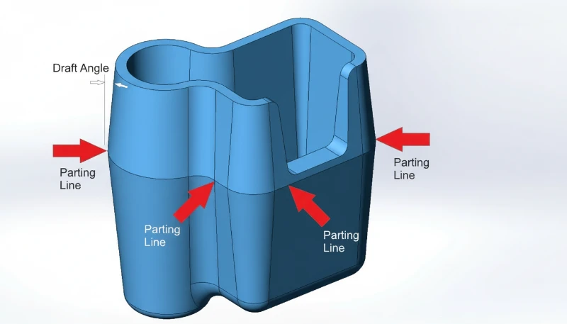
Does parting line affect draft angle requirements?
Yes, the parting line position directly determines which part surfaces require draft angles and in what orientation. Any surface that runs parallel to the mold opening direction — perpendicular to the parting plane — must have sufficient draft to release cleanly during ejection. When the parting line is relocated, the draft direction on surrounding surfaces may also need to change accordingly. Failing to coordinate parting line placement with draft requirements is a common root cause of ejection marks, surface scuffing, and parts sticking in the mold.
What is the difference between flat and composite parting lines?
A flat parting line lies entirely on a single plane and is the simplest to machine, making it ideal for straightforward geometries like flat panels, caps, and basic housings where cost efficiency is a priority. A composite parting line, by contrast, combines multiple flat and curved segments that transition across several planes. This allows the mold to accommodate complex features such as undercuts, stepped surfaces, and multi-directional ejection paths, but requires significantly more sophisticated CNC programming and increases tooling cost proportionally.
How does mold type affect parting line selection?
Mold type determines the number and function of parting lines within the tool. A standard two-plate mold has a single parting line at the mold split where the part is directly ejected. A three-plate mold introduces a second parting line to allow the runner system to separate automatically from the molded part. Stack molds, which double output capacity by molding parts at two levels simultaneously, require carefully balanced parting lines at each level to ensure that both halves eject correctly and in proper synchronization.
In our factory, our engineers review parting surfaces against demolding risk, flash risk, and mold fitting workload before steel cutting. In our experience at ZetarMold, the strongest designs connect the parting line to real production constraints across 47 injection molding machines, 90T to 1850T press capacity, and 8 senior engineers who review DFM, mold manufacturing, and trial feedback together. This prevents attractive CAD splits from becoming expensive mold corrections during sampling.
Why is Parting Line Design Critical for Injection Mold Quality?
Parting line design is critical because one placement error causes flash, slows cycle time, and forces expensive mold rework. The best designs balance aesthetics, ejection, and tooling cost in a single decision.
Ready to get your injection mold project started? Contact ZetarMold’s engineering team for competitive pricing, DFM feedback, and a production timeline — request your free quote today.
-
mold design: Mold design refers to the engineering process of planning the structure, parting surfaces, gating systems, and cooling channels of an injection mold. ↩
-
injection molding: Injection molding is a manufacturing process where molten material is injected into a mold cavity, cooled, and ejected as a finished part. ↩
-
mold processing: Mold processing refers to the machining, fitting, polishing, and validation work used to convert mold design into a working tool. ↩


