 Ir al contenido

In Injection Molding, ribs are essential features used to increase part stiffness without increasing overall wall thickness. The most common design mistakes involve improper wall thickness ratios (leading to sink marks), inadequate draft angles (causing ejection issues), and lack of base radii (resulting in stress concentrations). Adhering to standard guidelines—such as keeping rib thickness between 40–60% of the nominal wall and limiting height to 3x the wall thickness—ensures structural integrity and cosmetic quality.
Definición: Costillas de plástico
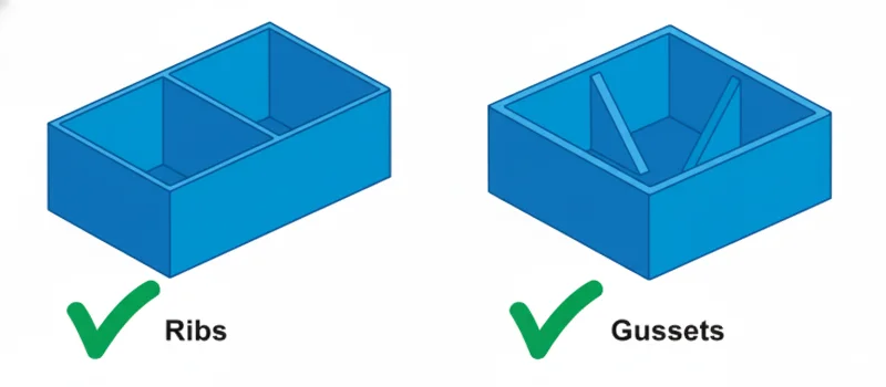
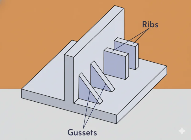
Costillas are thin, wall-like features that extend perpendicularly from a wall or plane in a plastic part. They are primarily used to add structural integrity, stiffness, and strength to a component without the cycle time penalty and material cost associated with increasing the entire wall thickness.
When designed correctly, ribs facilitate material flow (acting as internal runners) and prevent warping. However, poor design often leads to aesthetic defects like marcas de hundimiento (localized depressions) or structural failure due to stress concentration.
Ribs significantly increase part stiffness without the need to thicken the entire component wall.Verdadero
By increasing the moment of inertia, ribs provide structural rigidity while keeping material usage and cooling times low.
To maximize strength, rib thickness should always match the nominal wall thickness of the part.Falso
Ribs that are equal in thickness to the nominal wall create massive thermal mass at the intersection, causing sink marks and voids. Ribs should be 40–60% of the nominal wall.
Principales parámetros y directrices de diseño
The following parameters are critical standards used in the industry (referencing general guidelines from organizations like SPE and improper design correction manuals).
| Parámetro | Valor recomendado / Rango | Reason / Note |
|---|---|---|
| Root Thickness (t) | 40% – 60% of Nominal Wall (T) | Prevents marcas de hundimiento1 on the cosmetic side (Class A surface). Note: Glass-filled materials may allow up to 70%. |
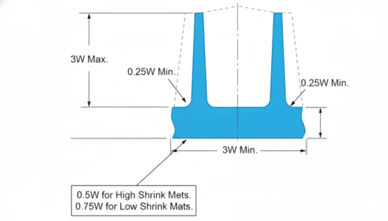
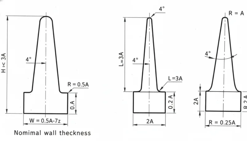
| Rib Height (H) | ≤ 3 × Nominal Wall (T) | Prevents gas traps and filling issues (short shots). Excessive height can also cause rib buckling under load. |
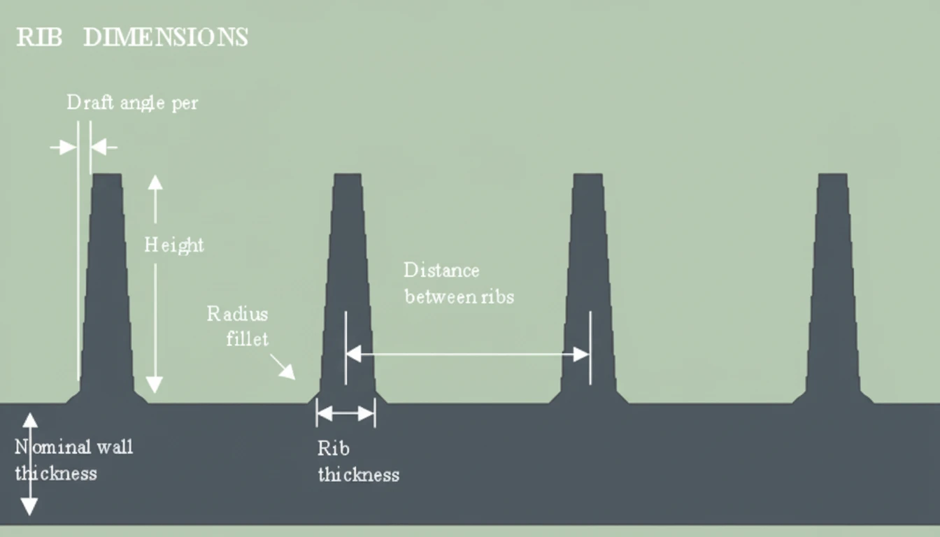
| Ángulo de calado | 0.5° – 1.5° per side | Facilitates part ejection. Textured surfaces require ≥ 1.5° or 1° per 0.025mm of texture depth. |
| Base Radius (R) | 25% – 50% of Nominal Wall (T) | Reduces stress concentration at the rib base. Too large a radius increases mass and risk of sink. |
| Spacing (S) | ≥ 2 × Nominal Wall (T) | Ensures adequate cooling between ribs; prevents thermal accumulation in the mold steel. |
| Grosor de la punta | ≥ 0.75 mm | Ensures the mold steel at the top of the rib is robust enough and the plastic can flow to the end. |
Advantages and Disadvantages of Ribbing
Using ribs effectively requires balancing structural needs with manufacturability.
| Característica | Ventajas | Disadvantages / Risks |
|---|---|---|
| Structural Integrity | significantly increases bending stiffness and load-bearing capacity. | Improper design leads to warping or internal stress. |
| Duración del ciclo | Faster cooling compared to a solid thick wall, reducing overall cycle time. | Deep ribs may require special venting or slower injection speeds to fill. |
| Coste del material | Reduces part weight compared to solid walls, lowering raw material usage. | Requires more complex mold machining (EDM) to create deep rib cavities. |
| Cosmetics | Can be used to hide flow lines or weld lines if positioned strategically. | High risk of sink marks on the opposite surface if the wall thickness ratio2 is ignored. |
Escenarios comunes de aplicación
Ribs are ubiquitous in injection molding. Typical applications include:
- Automotive Housings: Reinforcing large flat panels (e.g., door panels, dashboards) made of Polypropylene (PP) or Acrylonitrile Butadiene Styrene (ABS).
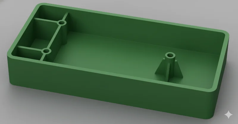
- Electrónica de consumo: Battery compartment structural supports and PCB mounting bosses in devices using Polycarbonate (PC) or PC/ABS blends.
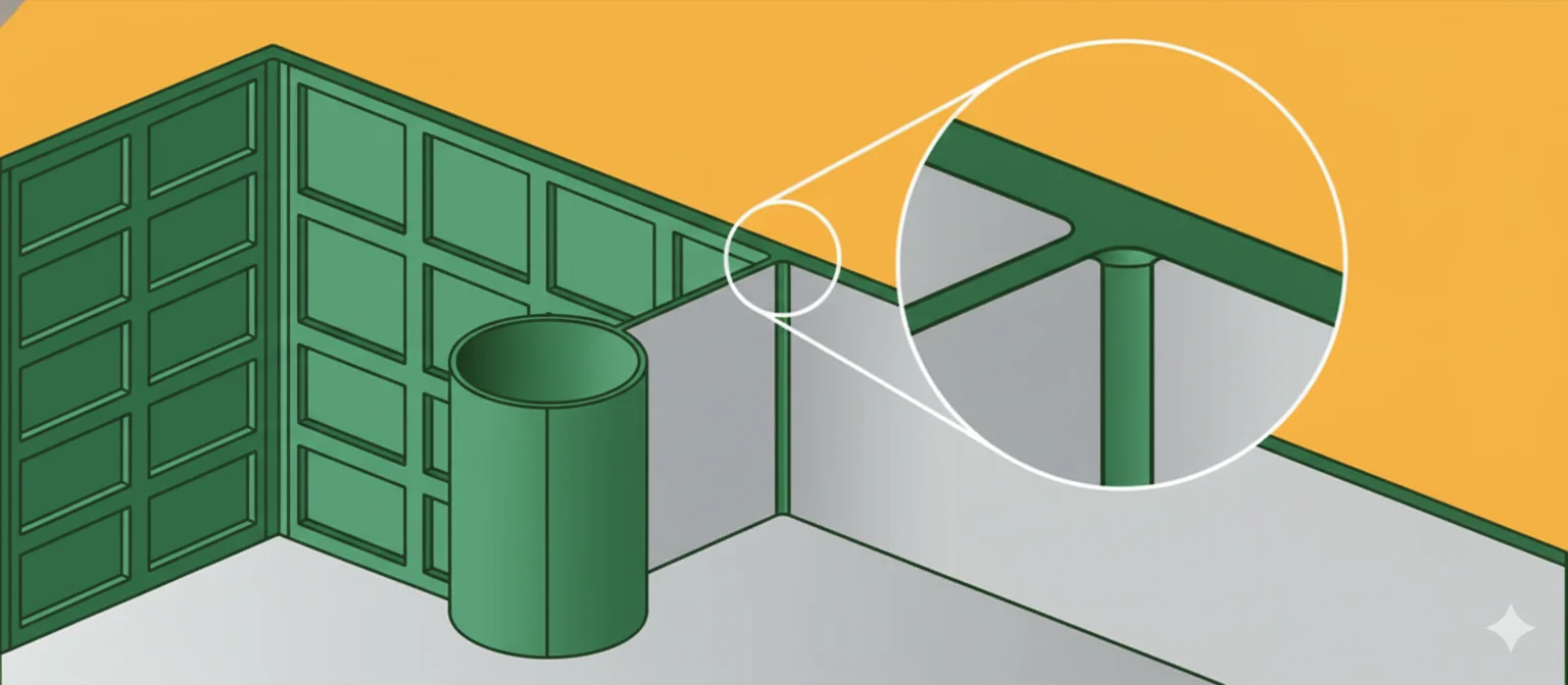
- Industrial Crates: Grid-pattern ribs on the bottom of heavy-duty pallets and crates to prevent bowing under load.
- Gears and Pulleys: Radial ribs connecting the hub to the rim to reduce mass while maintaining torque transmission capability.
Adding a base radius (fillet) to a rib helps distribute stress and prevents cracking.Verdadero
Sharp corners concentrate stress. A radius of 0.25x to 0.5x the wall thickness significantly improves fatigue resistance.
You can place ribs as close together as possible to maximize strength in a small area.Falso
Placing ribs too close prevents the mold steel between them from cooling effectively, leading to cycle time increases and potential warpage.
Step-by-Step Design Recommendations
To avoid common mistakes, follow this logical workflow when adding ribs to a CAD model.
- Establish Nominal Wall (T): Define the base wall thickness of the part based on material and structural requirements.
- Calculate Root Thickness (t):
- For amorphous materials (e.g., PC, ABS): Target 0.4 × T to 0.5 × T.
- For semi-crystalline materials (e.g., Polyamide 6 (PA6), Polyethylene (PE)): Target 0.5 × T to 0.6 × T.
- Apply Draft Angle: Apply a draft of at least 0.5° to the rib walls. Ensure the thickness at the top of the rib does not become too thin to fill (keep >0.75 mm).
- Add Base Radii: Add fillets at the intersection of the rib and the wall. Keep the radius small enough to avoid creating a "thick section" virtual circle that exceeds 120% of the nominal wall.
- Check Height and Spacing: Ensure the rib is not taller than 3 × T. If multiple ribs are needed, space them at least 2 × T apart to ensure the mold steel is robust and cooling is efficient.
- Coring Out (Optional): If a very thick rib is structurally necessary, consider "coring out" (removing material from the center) to maintain constant wall thickness rules.
Draft angles are mandatory on ribs to prevent vacuum lock and drag marks during ejection.Verdadero
Without draft, friction between the rib and the mold steel will damage the part surface or cause the rib to stick in the mold.
Increasing injection pressure is the best way to fill very thin, deep ribs.Falso
High pressure can cause flash or mold damage. The correct solution is increasing venting or slightly increasing rib thickness/flow channels.
FAQ: Common Rib Design Issues
Q: Why do ribs cause sink marks on the opposite side of the part?
A: Sink marks occur when the rib acts as a thermal mass. The intersection of the rib and the wall is thicker than the surrounding area, causing it to cool slower and shrink inward. Keeping the rib thickness at 50-60% of the wall helps minimize volumetric shrinkage3.
Q: Can I use ribs to assist with mold filling?
A: Yes, ribs can act as internal flow leaders (flow channels). However, if the rib is too thin compared to the wall, the flow will prefer the thicker wall (hesitation effect), potentially causing air traps or short shots in the rib.
Q: How does material selection affect rib design?
A: High-shrinkage materials (like Polyoxymethylene (POM) or PP) are more prone to sink marks and may require thinner ribs (40% ratio). Glass-filled materials shrink less and can tolerate slightly thicker ribs (up to 70% ratio) without visible sink.
Q: What is the "Steel Safe" approach for ribs?
A: When designing molds, it is safer to cut the rib cavity slightly smaller (making the plastic rib thinner) initially. It is easy to remove more metal (making the rib thicker) later if filling issues occur, but adding metal back is difficult and expensive.
Q: How should ribs be oriented regarding flow direction?
A: Ideally, ribs should run parallel to the flow of plastic to minimize flow resistance. Ribs perpendicular to flow can cause hesitation or weld lines4 where the flow front separates and rejoins.
Resumen
Avoiding common mistakes in plastic rib design requires strict adherence to wall thickness ratios and geometry standards. The "Golden Rule" is to maintain a rib root thickness of 40% to 60% of the nominal wall to prevent sink marks. Designers must also prioritize draft angles for ejection and base radii for stress reduction. By balancing structural requirements with injection molding constraints, engineers can produce parts that are both robust and cosmetically flawless.
-
Zetarmold Design Tips: A comprehensive guide on preventing cosmetic defects like sink marks through proper geometry ratios. ↩
-
ZetarMold Rib Guidelines: Detailed breakdown of wall thickness ratios and how they impact structural integrity vs. manufacturability. ↩
-
Xometry Resource Center: Explains the physics of volumetric shrinkage at rib intersections and how to calculate appropriate spacing. ↩
-
ZetarMold Defect Troubleshooting: Discusses how rib orientation relative to flow paths influences the formation of weld lines and flow marks. ↩


