 Ir al contenido

- CMM reports verify that molded parts meet GD&T tolerances
- FAI is mandatory before approving any new mold or process change
- Cross-check sample dimensions against drawing datums not just nominals
- Reliable suppliers provide Cpk data showing process capability
- Dimensional inspection costs 2-5%% of tooling but prevents 10x failures
When you order injection molded parts from a supplier—whether it is a first article run, a production batch, or a sample from a new mold—the dimensional inspection report is your single source of truth. If you cannot read and challenge that report confidently, you are flying blind. After 20+ years of running injection molds and reviewing thousands of CMM1 reports at our Shanghai factory, we have seen every trick in the book: cherry-picked samples, missing datums, inflated Cpk2 values, and reports that look perfect until you measure the parts yourself.
This guide walks you through exactly how to review CMM and sample reports from moldeo por inyección suppliers, what red flags to watch for, and how to set up a dimensional inspection process that actually protects your product quality.
What Is Dimensional Inspection in Injection Molding?
Dimensional inspection is the process of measuring molded part features against your engineering drawing to confirm they meet tolerance requirements. This includes checking hole diameters, wall thicknesses, flatness, positional accuracy, and profile tolerances using calibrated equipment such as CMMs, optical comparators, micrometers, and laser scanners. The most common tool is a Coordinate Measuring Machine (CMM), which uses a precision probe to map 3D coordinates on the part surface and compares them against the nominal CAD model.
If you are comparing vendors or planning procurement, our injection molding supplier sourcing guide covers RFQ prep, qualification, and commercial risk checks.
For a broader look at diseño de moldes de inyección, our pillar guide covers tooling structure, thermal control, and manufacturability tradeoffs.
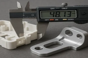
But dimensional inspection is not limited to CMMs. Depending on the tolerance range, part geometry, and production volume, inspectors may use optical comparators, digital micrometers, go/no-go gauges, surface roughness testers, or laser scanners. For tight-tolerance parts with tolerances of ±0.01 mm or tighter, a CMM with a sub-micron probe is non-negotiable. For commodity parts with generous tolerances above ±0.1 mm, a well-calibrated digital caliper might be sufficient. The key principle: your measurement tool must have at least 10 times better resolution than the tolerance you are trying to verify. This is the 10:1 rule in metrology, and ignoring it is one of the most common mistakes we see in supplier inspection reports.
How Does a CMM Report Work and What Should You Look For?
A CMM report contains three core elements: measured value, nominal value, and deviation. Most reports also show the upper and lower tolerance limits, so you can immediately see whether a dimension is in-spec or out-of-spec. The report format varies by supplier—some use standardized AS9102 or PPAP formats, others use their own templates. Regardless of format, here is what you should always check: First, verify that the report references the correct drawing revision. We have seen cases where a supplier measured parts against an outdated drawing and everything looked perfect—until the customer discovered the parts did not match the current revision.
Second, confirm that the datum reference frame on the report matches your drawing. If the CMM program uses a different datum setup than your drawing specifies, every positional measurement will be wrong. Third, look at the actual deviation values, not just the pass/fail column. A dimension that is deviating consistently to one side of the tolerance band may indicate a systematic mold issue, even if it is technically within spec.
Why Is First Article Inspection (FAI) Critical for Injection Molded Parts?
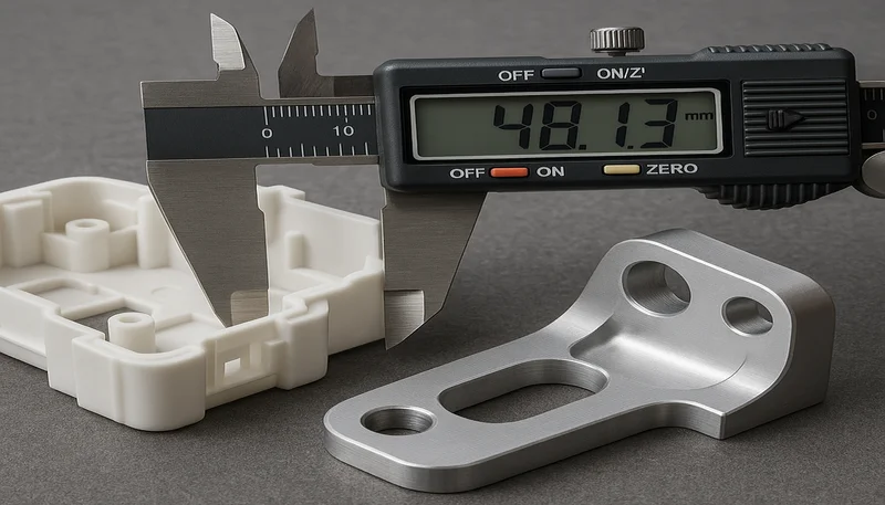
Inspección de Primer Artículo (FAI3) is the most important dimensional inspection you will ever perform on an injection molded part. It is the first comprehensive measurement of parts produced from a new mold or after a significant process change. The purpose is straightforward: prove that the mold and process produce parts that meet every dimension on the drawing before you commit to volume production. Skipping FAI or treating it as a formality is one of the most expensive mistakes in manufacturing. We have seen cases where a customer approved a mold based on a quick visual check, ran 50,000 parts, and then discovered during assembly that a critical hole was 0.05 mm off-position. The entire batch was scrap.
A proper FAI would have caught this in the first 3 parts.
A proper FAI should measure every dimension on the drawing—not just the ones the supplier considers critical. In injection molding, what seems like a non-critical dimension can become critical in the context of your full assembly. The standard practice is to use the AS9102 format or the PPAP dimensional results section, which requires reporting every characteristic. At our facility, we run FAI on every new mold using CMM programs that are independently verified against the customer drawing. We also measure a minimum of 3 to 5 samples from the initial run to capture process variation. A single sample tells you almost nothing about process capability—you need multiple parts to see the real picture.
In our Shanghai factory, we run 47 injection molding machines ranging from 90T to 1850T, and our 8 senior engineers review every FAI report before it leaves the building. This is not optional—it is how we catch measurement errors before they reach the customer.
How Do You Read GD&T Symbols on a Supplier Sample Report?
GD&T is the standard language for dimensional specifications on engineering drawings. If your supplier CMM report does not address GD&T callouts, it is incomplete. The most common GD&T symbols in injection molding inspection are: flatness, parallelism, perpendicularity, position, concentricity, and profile of a surface. Each has a tolerance zone defined in the feature control frame. When reviewing a CMM report, verify that the supplier measured each GD&T callout correctly. For example, a position tolerance at MMC requires the CMM to apply bonus tolerance based on actual datum feature sizes.
When reviewing a CMM report, you should verify that the supplier has measured each GD&T callout correctly. For example, a position tolerance of 0.1 mm at MMC (Maximum Material Condition) requires the CMM to apply the correct bonus tolerance based on the actual size of the datum features. If the supplier simply reports the basic X-Y coordinates without applying the MMC bonus, the position check is wrong.
Another common issue is datum alignment. GD&T tolerances are defined relative to specific datums labeled A, B, C on the drawing. The CMM program must establish these datums in the correct order and using the correct features. If Datum A is defined as the bottom surface but the CMM program uses the top surface as Datum A, every positional measurement downstream will be offset. Always ask your supplier to show you the datum alignment setup in the CMM program—it takes 5 minutes and can save you from accepting bad parts or rejecting good ones.
What Is Cpk and Why Does It Matter for Injection Molding Suppliers?
Cpk (Process Capability Index) is the single most important statistical metric in dimensional inspection. It tells you not just whether parts are currently in spec, but whether the process is capable of consistently producing in-spec parts over time. A Cpk of 1.0 means the process spread exactly fills the tolerance band—any shift in the process will produce out-of-spec parts. A Cpk of 1.33 means the process spread uses only 75% of the tolerance band, giving you a safety margin. A Cpk of 1.67 or higher is typically required for critical dimensions in automotive and medical applications.
Here is the key insight that most purchasing teams miss: a supplier who only reports pass/fail results without Cpk data is not giving you enough information. A dimension might pass on all 5 samples but have a Cpk of 0.8, meaning the process is barely capable and will produce out-of-spec parts as soon as material batch, mold temperature, or ambient conditions shift slightly.
When reviewing Cpk data, look for values based on at least 30 samples—anything less is statistically unreliable. Also verify that the Cpk calculation uses the correct tolerance limits from your drawing. We have seen suppliers calculate Cpk using unilateral tolerances when the drawing specifies bilateral tolerances, which artificially inflates the Cpk value. The formula is straightforward: Cpk equals the minimum of (USL minus mean) divided by 3 sigma, and (mean minus LSL) divided by 3 sigma, where USL and LSL are your upper and lower specification limits, and sigma is the standard deviation of the measured values. If you want to verify the calculation yourself, ask the supplier for the raw measurement data.
What Are the Red Flags in a Supplier Dimensional Inspection Report?
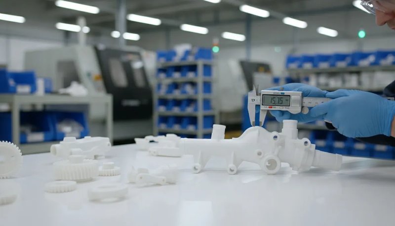
After reviewing thousands of inspection reports, these are the red flags that should make you stop and ask questions. First, missing dimensions—if the report does not cover every dimension on the drawing, ask why. Sometimes suppliers skip dimensions they know are out-of-spec, hoping you will not notice. Second, suspiciously perfect measurements. Real injection molding processes have variation. If every measured value is exactly at nominal with zero deviation, something is wrong with the measurement process, not right with the parts. Third, inconsistent sample counts. If some dimensions are measured on 5 samples and others on only 1 or 2, the supplier may be hiding variation on the less-sampled features. Fourth, no measurement uncertainty stated.
Every measurement has uncertainty, and a professional inspection report should state the measurement uncertainty, typically expressed as plus or minus X mm at a 95% confidence level. Fifth, measurements taken at room temperature when the drawing specifies dimensions at a different temperature. Thermal expansion can shift dimensions by several microns on larger parts.
Another critical red flag is when the inspection report uses different measurement methods than what was agreed upon in the quality agreement. If you specified CMM measurement and the report shows caliper measurements for tight-tolerance features, the results are not trustworthy. Similarly, if the report shows measurements of parts that were measured immediately after molding (while still warm) versus parts that were allowed to cool and stabilize, the dimensional data will be unreliable. Injection molded parts can shrink 0.5% to 2.5% during cooling, and measuring parts before they have reached thermal equilibrium will give you artificially larger dimensions.
How Do You Set Up an Effective Dimensional Inspection Process with Your Supplier?
An effective dimensional inspection process is built on three agreements: what to measure, how to measure it, and how to handle out-of-spec parts. Start with a measurement plan listing every critical dimension, the method, sample size, and acceptance criteria. We recommend three tiers: Tier 1 (critical, affecting fit or safety) measured on every part; Tier 2 (important, affecting assembly) measured on a statistical sample; Tier 3 (reference only) measured at FAI.
This tiered approach focuses inspection resources where they matter most and avoids the cost of measuring every dimension on every part.
Next, agree on the measurement method and equipment for each tier. For Tier 1 dimensions with tolerances tighter than ±0.05 mm, CMM measurement is the standard. For Tier 2 dimensions with tolerances between ±0.05 mm and ±0.2 mm, optical measurement or precision gauges may suffice. For Tier 3, basic hand tools are usually adequate. Document all of this in a measurement plan and have both parties sign off before the first article run. Finally, define the escalation path: who gets notified when a dimension is out of spec, what corrective action is required, and who approves the disposition of affected parts. Having this agreed in advance prevents disputes later.
In our experience, the most successful supplier relationships are the ones where the quality expectations are spelled out in writing before the first shot is molded.
“Cpk values below 1.0 indicate that a manufacturing process cannot consistently produce parts within specification limits.”Verdadero
A Cpk below 1.0 means the natural process spread exceeds the tolerance band, so even a perfectly centered process will produce some out-of-spec parts.
“A dimensional inspection report showing zero deviation on all measurements proves excellent process control.”Falso
Zero deviation across all dimensions is actually a red flag—it suggests measurement error, data fabrication, or insufficient measurement resolution rather than perfect parts.
What Are the Most Common Measurement Mistakes in Injection Molded Part Inspection?
The most common mistake we see is measuring parts before they have fully cooled and stabilized. Injection molded parts—especially semi-crystalline materials like nylon, POM, and PEEK—continue to shrink for hours after molding as the crystalline structure develops. Measuring these parts too early gives dimensions that are larger than the final stable dimensions. The standard practice is to wait a minimum of 4 to 24 hours after molding, depending on the material and wall thickness, before taking critical measurements. Another common error is not accounting for measurement force. Contact probes on CMMs and calipers apply physical force to the part surface, which can compress flexible materials like TPE and TPU.
For these materials, non-contact optical measurement or minimum-force probes should be used.
A third mistake is failing to establish a consistent measurement temperature. Most engineering drawings specify dimensions at 20 degrees Celsius, but factory floors often range from 10 degrees in winter to 35 degrees in summer. A 100 mm steel part will expand approximately 0.012 mm for every 1 degree increase in temperature. For a plastic part with a higher coefficient of thermal expansion, the effect is even larger. Professional inspection labs maintain temperature control at 20 degrees plus or minus 1 degree, but if your supplier is measuring parts on the production floor, you need to ask about temperature compensation. Finally, insufficient sample size is a pervasive problem. A single measurement tells you almost nothing about process capability.
You need a minimum of 5 samples for FAI and 30 samples for a reliable Cpk calculation. Any supplier who provides Cpk data based on fewer than 30 samples is giving you a number that is not statistically meaningful.
How Often Should Dimensional Inspection Be Performed During Production?
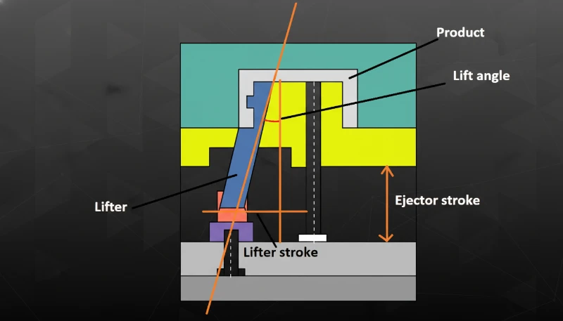
The right inspection frequency is determined by your production volume, part complexity, and quality requirements. Measure every part for low-volume batches under 1,000 parts. Use AQL statistical sampling for 1,000 to 50,000 parts, with AQL 1.0 for critical dimensions and AQL 2.5 for non-critical ones. For high-volume production above 50,000 parts, implement SPC with X-bar and R charts tracking critical dimensions in real time.
SPC allows you to detect process drift before parts go out of spec, which is far more effective than catching defective parts after the fact.
Beyond routine sampling, there are specific trigger points that require dimensional inspection: mold installation or changeover, material lot change, machine parameter adjustment, after any mold maintenance or repair, and at the start of each production shift. Each of these events can introduce dimensional variation, and inspection at these points catches problems early. We also recommend a periodic mold qualification—typically every 50,000 shots or quarterly, whichever comes first—where you run a mini-FAI on the current production parts to verify that the mold has not worn beyond acceptable limits. Mold wear is gradual and often invisible until it accumulates enough to push dimensions out of spec. Regular monitoring catches this trend early.
“Injection molded parts from semi-crystalline materials should be measured at least 4 hours after molding.”Verdadero
Semi-crystalline polymers like nylon and POM continue crystallizing and shrinking for hours post-mold. Measuring too early yields artificially large dimensions.
“AQL sampling at level 2.5 guarantees zero defective parts will reach the customer.”Falso
AQL is an acceptance sampling method that allows a defined percentage of defects. It does not guarantee zero defects—it balances inspection cost against quality risk.
What Should Be in Your Dimensional Inspection Quality Agreement with a Supplier?
A well-drafted quality agreement is your legal and operational foundation for dimensional inspection. At minimum, it should include: the drawing revision and date that the agreement applies to, a complete list of critical dimensions with tolerances and measurement methods, the sampling plan specifying how many parts are measured and at what frequency, the Cpk requirements for critical dimensions (typically 1.33 minimum for standard parts, 1.67 for critical applications), the reporting format and turnaround time for inspection reports, the escalation and corrective action process for out-of-spec findings, and the criteria for mold qualification and requalification. The agreement should also specify who performs the inspection—whether it is the supplier’s in-house lab, a third-party lab, or your own audit team.
If the supplier uses a third-party lab, you need the right to audit that lab and verify their calibration records and measurement capability.
One frequently overlooked element is the measurement equipment calibration requirement. All measurement equipment used for dimensional inspection must be calibrated to traceable national or international standards (NIST in the US, NIM in China, NPL in the UK), and calibration certificates should be current and available for review. The calibration interval depends on the equipment type and usage frequency, but annual calibration is the minimum standard for CMMs and precision gauges. If a supplier cannot provide current calibration certificates, their measurement data is not trustworthy. Another element to include is the disposition process for non-conforming parts: who decides whether to scrap, rework, or accept parts with deviations, and what authority level is required for each decision.
Frequently Asked Questions About Dimensional Inspection for Injection Molding
Preguntas frecuentes
What Is the Standard Tolerance for Injection Molded Parts?
The general standard tolerance for injection molded parts is plus or minus 0.1 mm per 25 mm of part dimension, as defined by ISO 20457 and DIN 16742. However, tight tolerances of plus or minus 0.025 mm are achievable on critical features with proper mold design, process control, and material selection. The achievable tolerance depends heavily on the material—amorphous materials like ABS and PC typically hold tighter tolerances than semi-crystalline materials like nylon or POM, which have higher shrinkage rates and greater post-molding dimensional change. Always specify your critical tolerances on the drawing and discuss achievable limits with your supplier before tooling begins.
How Many Samples Should Be Measured for First Article Inspection?
Industry best practice requires measuring a minimum of 3 to 5 samples from the initial production run for FAI. For statistical process capability studies, you need at least 30 samples to calculate a reliable Cpk value. The samples should come from different mold cavities in multi-cavity molds, different machine cycles, and different positions within the cycle to capture the full range of process variation. Single-cavity molds still require multiple samples because shot-to-shot variation in parameters like injection pressure, holding time, and mold temperature affects dimensional consistency.
What Measurement Equipment Is Best for Inspecting Injection Molded Parts?
The best measurement equipment depends on the tolerance range and part complexity. For tight tolerances below plus or minus 0.05 mm, a Coordinate Measuring Machine (CMM) with a touch probe or optical sensor is the gold standard. For tolerances between plus or minus 0.05 mm and plus or minus 0.2 mm, optical comparators and vision measurement systems offer fast, non-contact measurement. For quick checks on non-critical dimensions, digital calipers and micrometers are cost-effective and portable. The key principle is that the measurement tool resolution must be at least 10 times finer than the tolerance being verified.
How Do You Verify a Supplier CMM Measurement Accuracy?
To verify a supplier’s CMM accuracy, start by requesting their calibration certificate and measurement uncertainty statement. Then perform a measurement systems analysis (MSA) or gauge R and R study using known reference standards. You can also send the same set of parts to an independent third-party lab for comparison measurement. If the supplier’s measurements differ from the independent lab by more than the stated measurement uncertainty, there is a problem with either the equipment calibration or the measurement method. A trustworthy supplier will welcome this verification.
What Is the Difference Between FAI and In-Process Inspection?
FAI (First Article Inspection) is a one-time, comprehensive dimensional verification performed on the first parts from a new mold or after a process change, measuring every dimension on the drawing. In-process inspection is an ongoing sampling inspection performed during production, typically measuring only critical dimensions on a statistical sample of parts. FAI establishes the baseline capability of the mold and process, while in-process inspection monitors consistency and detects drift over time. Both are essential components of a complete quality assurance system.
Can Injection Molded Parts Be Measured Immediately After Molding?
No, injection molded parts should not be measured immediately after molding, especially those made from semi-crystalline materials like nylon, POM, or PEEK. These materials continue to crystallize and shrink for hours after molding. The recommended practice is to wait a minimum of 4 hours for amorphous materials and 24 hours for semi-crystalline materials before taking critical dimensional measurements. Measuring too early gives artificially large dimensions that do not reflect the part’s final stable size. For production environments where parts are measured on-site, consider using a standardized cooling protocol with a minimum 4-hour ambient rest in a temperature-controlled inspection area before measurement.
What Happens When a Dimension Is Out of Tolerance?
When a dimension is out of tolerance, the first step is to verify the measurement by having a different operator or a different piece of equipment re-measure the same part. If the deviation is confirmed, the parts should be quarantined and the root cause investigated. Common root causes include mold wear, process parameter drift, material batch variation, and measurement error. The corrective action depends on the root cause: mold repair, process adjustment, material change, or measurement method correction. A formal corrective action report should document the findings and prevent recurrence.
Dimensional inspection is not a checkbox exercise—it is the backbone of your product quality assurance. If you are sourcing injection molded parts and want a supplier who takes dimensional accuracy as seriously as you do, we should talk. At ZetarMold, we have 20+ years of injection molding experience, 47 injection molding machines from 90T to 1850T, and a dedicated team of 10+ QC specialists who perform FAI and in-process dimensional inspection on every production order. Our ISO 9001 and ISO 13485 certified quality system ensures that every CMM report you receive is backed by calibrated equipment and verified procedures. Ready to discuss your dimensional inspection requirements?
Get in touch with our team and let us show you what proper dimensional control looks like.
-
CMM: A Coordinate Measuring Machine is a device that measures the geometry of physical objects by sensing discrete points on their surface using a mechanical, optical, laser, or white light probe. ↩
-
Cpk: Process Capability Index is a statistical measure of a process’s ability to produce output within specification limits. ↩
-
FAI: First Article Inspection is a formal method to verify that the production process reliably produces parts that meet the specifications defined in the engineering drawing. ↩



 EN
EN  ES
ES  FR
FR  DE
DE  PT
PT  AR
AR  RU
RU  JA
JA  KO
KO  IT
IT  NL
NL  TR
TR  PL
PL 