 Zum Inhalt springen

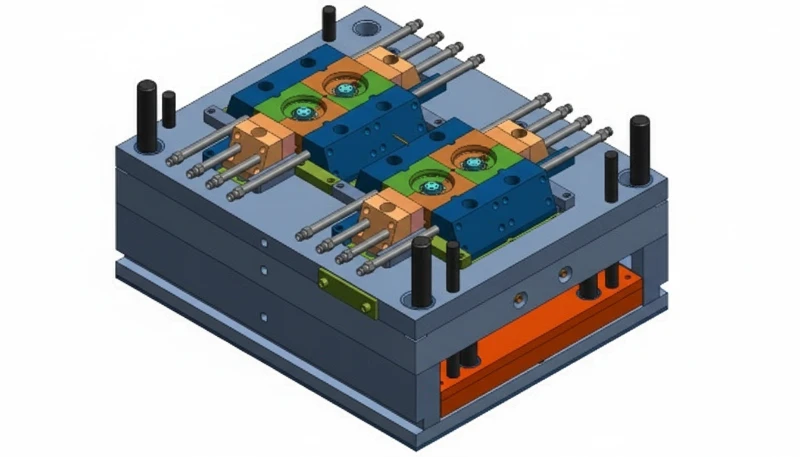
Das Anguss-System ist der Punkt, an dem geschmolzener Kunststoff in den Hohlraum eintritt, und sein Typ, seine Größe und Position bestimmen das Fließverhalten, die Schweißnahtposition, die Nachdruckeffizienz und die sichtbare Markierung, die am Bauteil zurückbleibt. Bei Präzisionswerkzeugen ist die Angussgestaltung eine zentrale technische Entscheidung und keine nachträgliche Überlegung. Wenn der Anguss falsch dimensioniert ist, wird keine noch so feine Prozesseinstellung die erforderliche Maßhaltigkeit gewährleisten.
This article walks through the critical decisions in Spritzgussformdesign1—from steel selection and gate placement to cooling strategy and Moldflow-Analyse2. Whether you are designing your first precision mold or troubleshooting your fiftieth, these are the decisions that separate a mold that runs 500,000 shots from one that needs rework after 10,000.
- Mold design starts at the part design stage—fix DFM issues before cutting steel.
- Steel choice (P20 vs H13 vs S136) determines tool life, cost, and part finish quality.
- Gate location and type directly affect weld lines, air traps, and dimensional accuracy.
- Cooling channel design accounts for up to 70% of cycle time optimization.
- Tolerances below ±0.05 mm require specialized mold features and process controls.
- Always run mold flow simulation before committing to tooling fabrication.
What Makes a Precision Injection Mold Different from a Standard Mold?
Dieser Abschnitt behandelt, was eine Präzisionsspritzgussform von einer Standardform unterscheidet und welche Auswirkungen dies auf Kosten, Qualität, Zeitplan oder Beschaffungsrisiken hat. Eine Präzisionsform unterscheidet sich von einer Standardform in drei messbaren Punkten: engere Maßtoleranzen (±0,01 bis ±0,05 mm gegenüber ±0,1 bis ±0,25 mm), hochwertigere Oberflächengüten (SPI A-1 bis A-3 gegenüber B- oder C-Grad) und optimierte Zykluszeiten im einstelligen Sekundenbereich. Dies sind keine schrittweisen Verbesserungen – sie erfordern grundlegend andere Ansätze bei der Stahlauswahl, der Kühlungsauslegung und der Prozessvalidierung.
Precision molds require tighter steel grades, more sophisticated cooling layouts, multi-axis CNC finishing, and often in-process measurement systems. A standard mold might take 3–4 weeks to build. A precision mold for the same part could take 8–12 weeks and cost 2–3 times more. But the payoff is consistency—parts that match the CAD model shot after shot, with scrap rates under 1%.
In our Shanghai facility, we have built precision molds for medical device components where the tolerance on a sealing surface was ±0.015 mm. That is not something you achieve with a standard mold approach. It requires dedicated steel selection, thermal management in the mold base, and process validation that runs hundreds of samples before the first production batch.
The precision gap becomes most visible in multi-cavity molds. If you are running an 8-cavity mold for a connector housing, each cavity must produce identical parts. Any variation in cooling, gate size, or venting between cavities shows up as dimensional spread across the parts from the same shot. That is why precision multi-cavity molds require balanced runner layouts, individually adjustable cooling, and cavity-by-cavity dimensional tracking during sampling.
How Do You Select the Right Steel for a Precision Mold?
Tool steel selection is the first irreversible decision in Formgestaltung. The right choice depends on three factors: production volume, the material being molded, and surface finish requirements. Get this wrong and you either overspend on tooling or face premature mold wear.
| Stahlsorte | Härte (HRC) | Am besten für | Expected Tool Life |
|---|---|---|---|
| P20 / P20HH | 28–36 | Low-volume (under 100K shots), general purpose | 100K–300K shots |
| H13 | 44–52 | High-temperature resins (PEEK, LCP), high volume | 500K–1M+ shots |
| S136 / STAVAX | 48–54 | Mirror-polish finishes, medical/optical, corrosion resistant | 500K–1M+ shots |
| NAK80 | 37–41 | Pre-hardened, good machinability, mid-volume | 300K–500K shots |
| 718H | 33–38 | General purpose, good polishability, cost-effective | 200K–500K shots |
The common mistake is over-specifying steel. Not every mold needs H13. If you are molding 20,000 parts in PP with a matte surface, P20 is perfectly adequate and saves 30–40% on tooling cost. But if you are running glass-filled nylon at 300°C with a SPI A-2 finish, you need hardened steel—anything softer will erode at the gate area within weeks.
For precision work, we typically specify S136 or STAVAX for cavities that need mirror finishes, paired with H13 for core inserts that see high thermal cycling. The combination gives you the surface quality precision parts demand with the thermal durability high-volume production requires. Our 8 senior engineers each have 10+ years of experience selecting and specifying these materials for specific applications.
At ZetarMold, our in-house mold manufacturing facility in Shanghai includes CNC machines, wire cutters, EDMs, grinders, and precision engravers—all supporting a monthly capacity of 100+ mold sets. With 8 senior engineers averaging 10+ years of experience, we select steel grades based on actual production conditions: resin type, expected volume, and required surface finish, not theoretical recommendations from a catalog.
What Role Does Shrinkage Compensation Play in Mold Design?
Every plastic shrinks as it cools, and compensating for that shrinkage is one of the most mathematically demanding aspects of precision mold design. The shrinkage rate for common engineering plastics ranges from 0.2% for amorphous materials like PC to 2.5% for semi-crystalline materials like POM. You must compensate directionally, because shrinkage is not uniform across the part.
A 100 mm nominal dimension in PA66 with 1.3% shrinkage means the cavity must be cut to 101.3 mm. But that is the simplified version. In reality, shrinkage varies with wall thickness, flow direction, gate proximity, and holding pressure. A rib that is 2 mm thick will shrink differently than the adjacent 4 mm wall. In our mold manufacturing experience, we have seen parts where the difference between flow-direction and transverse-direction shrinkage exceeded 0.4%—enough to push a ±0.05 mm tolerance out of spec.

This is exactly why precision molds require mold flow analysis before steel cutting. The simulation predicts how each region of the part will shrink, allowing the tool designer to apply differential compensation—slightly oversizing some cavity features, undersizing others, and adjusting the mold geometry so that the final part lands within tolerance after it cools. Without simulation, you are guessing, and re-cutting hardened steel is expensive and slow.
How Should You Design the Gate and Runner System?
Dieser Abschnitt behandelt die Auslegung des Anguss- und Verteilersystems und dessen Auswirkungen auf Kosten, Qualität, Zeitplan oder Beschaffungsrisiken. Der Anguss ist die Stelle, an der das geschmolzene Kunststoff in den Hohlraum eintritt, und sein Typ, seine Größe und Position bestimmen das Fließmuster, die Schweißnahtposition, die Nachdruckeffizienz und die sichtbare Markierung am Teil. Bei Präzisionsformen ist die Angussauslegung eine zentrale technische Entscheidung, kein nachträglicher Gedanke. Wenn der Anguss falsch ist, wird keine noch so feine Prozesseinstellung die erforderliche Maßkonstanz liefern.
Formenwerkzeug-InspektionsinstrumenteWahr
The gate determines the fill pattern inside the cavity. A poorly placed gate creates uneven packing, causing one side of the part to be dimensionally different from the other. In multi-gate designs, weld lines form where flow fronts meet—if these land on a structural feature, part strength drops 20–40%.
“A larger gate always produces better quality parts.”Falsch
An oversized gate leaves a large vestige that requires secondary trimming, increases the freeze time (slowing cycle), and can cause over-packing near the gate, leading to flash. Gate size must balance fill speed, packing pressure transfer, and clean degating.
For precision parts, the most common gate types are submarine (tunnel) gates, which leave minimal visible marks, and direct (sprue) gates for single-cavity molds where maximum packing is needed. Edge gates work for flat parts but leave a visible mark that must be managed. The choice depends on part geometry, aesthetic requirements, and production volume.
The runner system connects the sprue to the gates. In precision molding, hot runner systems are often preferred because they eliminate cold runner waste, reduce cycle time, and deliver more consistent melt temperature to each cavity. However, hot runners add USD 3,000–15,000 to tooling cost and introduce potential maintenance points. For multi-cavity precision molds running high-volume production, the payback is usually within the first 50,000 shots.
Why Is Cooling Channel Design Critical for Precision Parts?
Cooling accounts for 60–70% of the total Spritzgießen cycle. In precision molding, cooling also directly affects part quality—uneven cooling causes differential shrinkage, warpage, and internal stress that push dimensions out of tolerance. A well-designed cooling system removes heat uniformly and quickly; a poorly designed one creates hot spots that distort parts and drive up scrap rates.
Standard drilled cooling channels are straight lines through the mold base. They work for simple geometries but cannot follow complex part contours. For precision parts with varying wall thicknesses or deep ribs, conformal cooling—channels that follow the cavity surface—is dramatically more effective. Research and our own production data show conformal cooling reduces cycle time by 20–35% and improves dimensional consistency by 15–25%.

The practical challenge with conformal cooling is manufacturing. Traditional drilling cannot create curved channels. You need either metal 3D printing (selective laser melting) for the core inserts or fabricated baffle and bubble designs that approximate conformal flow. Both approaches add cost and extended timelines, which is why selecting a qualified Spritzgießer early in the project matters. In our facility, we evaluate each precision mold project individually—sometimes a well-designed baffle system achieves 80% of conformal cooling benefit at 30% of the cost.
What Are the Key Part Design Features That Affect Mold Precision?
The key part design features that affect mold precision are the main categories or options explained in this section. The best mold design cannot fix a bad part design. Precision starts at the CAD stage, and there are several features that either enable or prevent precision molding. Addressing these during the DFM review saves weeks of mold rework later.
Draft angles are non-negotiable. Even precision parts need at least 0.5° of draft on vertical surfaces; 1–2° is preferred. The common argument—that draft changes dimensions—misses the point. Without draft, the part drags on the cavity wall during ejection, causing scratches, dimensional variation, and eventual cavity damage. The solution is to design the draft into the tolerance stack from the beginning.
Wall thickness uniformity is the second critical factor. Variations greater than 15–20% between adjacent sections cause differential cooling, sink marks, and internal stress. If your part has thick sections next to thin ones, you either need to core out the thick areas or accept that they will shrink differently. We regularly work with customers during the DFM review to adjust wall thickness transitions before the mold is cut.
Corner radii are the third. Sharp internal corners create stress concentrations that cause cracking in-service and make mold filling inconsistent. A minimum internal radius of 0.5 mm is standard; for precision parts loaded in use, 1.0 mm or more is recommended. External corners should also have a small radius—0.25 mm minimum—to prevent steel chipping at the cavity edge during the millions of clamp cycles the mold will endure.
“Draft angle as small as 0.5° is sufficient for precision ejection on polished cavity surfaces.”Wahr
On cavities polished to SPI A-2 or better, the surface friction is low enough that 0.5° of draft allows clean ejection for most engineering plastics. However, for glass-filled materials or textured surfaces, 1.5–3° is necessary to prevent drag marks.
“Precision parts cannot have any undercuts because side actions reduce accuracy.”Falsch
Modern lifter and slide mechanisms can maintain positional accuracy within ±0.02 mm. The key is designing the side action with hardened wear plates and adequate guiding. Undercuts should be avoided when possible, but they are not automatic disqualifiers for precision work.
What Inspection and Validation Steps Ensure Mold Precision?
A precision mold is not finished when the steel is cut—it is finished when the first articles pass inspection. Validation is the last and most critical phase, and it requires specific equipment and procedures that many mold shops skip in the interest of speed.
The sequence we follow: first, CMM (Coordinate Measuring Machine) verification of the cavity dimensions before the mold ever sees plastic. This catches steel cutting errors—typically, cavity dimensions should be within 80% of the shrinkage-compensated tolerance before molding begins. Second, short-shot analysis—gradually filling the cavity to check that the flow matches the mold flow simulation3. Third, full-shot dimensional analysis using CMM or optical measurement on 30–50 samples to establish process capability (Cpk ≥ 1.33 is the minimum for precision work; ≥ 1.67 for medical).
Our QC team of 10+ specialists uses a six-step quality control process—from incoming material inspection through in-process checks to final outgoing verification. For precision molds, we add a mold-specific capability study that runs 100+ consecutive shots to confirm that dimensional variation stays within specification over time. This catches issues like cavity wear, cooling drift, and gate erosion before they affect production parts.
We also perform a 24-hour post-molding dimensional check in addition to immediate measurement. This catches delayed dimensional shifts caused by residual stress relaxation or continued crystallization—particularly important for semi-crystalline materials like POM and PA66, where post-molding shrinkage can continue for 48 hours or more.
Häufig gestellte Fragen zum Präzisionsspritzgussformenbau
What tolerance can a precision injection mold achieve?
A well-designed precision injection mold can reliably hold tolerances of ±0.01 to ±0.05 mm on critical dimensions, depending on part geometry, material selection, and mold design complexity. Achieving ±0.01 mm consistently requires hardened steel cavities (S136 or H13), optimized conformal cooling layouts, and process windows validated through capability studies with Cpk ≥ 1.67. For most engineering applications, ±0.025 to ±0.05 mm is a practical and cost-effective target that balances precision requirements with production economics. For critical medical and optical applications, we recommend targeting ±0.025 mm as a design tolerance and validating the process Cpk over at least 100 consecutive shots.
How much does a precision injection mold cost compared to a standard mold?
A precision mold typically costs 2–3 times more than a standard mold for the same part geometry. The premium comes from higher-grade steel (S136 or H13 instead of P20), multi-axis CNC finishing, additional validation steps including CMM measurement, and more sophisticated cooling systems such as conformal channels. For a mid-complexity part, this might mean USD 15,000–25,000 versus USD 6,000–10,000 for standard tooling. However, the lower scrap rate and longer tool life often recover the premium within the first production run. In our experience building precision molds monthly, the additional investment pays for itself through reduced scrap and fewer production interruptions.
How long does it take to build a precision injection mold?
Build time ranges from 6 to 12 weeks depending on complexity and steel requirements. A single-cavity mold with moderate features might take 6–8 weeks from design approval to T0 sampling. A multi-cavity mold with side actions, lifters, and conformal cooling can take 10–14 weeks. The validation phase—T0 sampling, dimensional analysis on 30–50 parts, and any necessary revisions—adds another 1–3 weeks on top of mold fabrication. Rush timelines are possible but often compromise the validation step, which we do not recommend for precision applications.
Do all precision molds require hot runner systems?
No, not all precision molds require hot runner systems. Hot runners are strongly recommended for multi-cavity precision molds and high-volume production because they eliminate cold runner waste and deliver more consistent melt temperature to each cavity, which improves dimensional uniformity. However, for single-cavity molds or low-volume precision work, a cold runner with a direct sprue gate can achieve the same dimensional accuracy at significantly lower tooling cost. The decision between hot and cold runners should be made during the DFM review phase, considering annual volume projections and material characteristics.
What is the most common mistake in precision mold design?
The most frequent error is underestimating the interaction between cooling channel design and final part dimensional accuracy. Engineers often focus intensely on cavity tolerances and steel cutting precision but neglect cooling uniformity. This leads to parts that measure correctly immediately after molding but drift out of tolerance as internal stresses relax over 24–48 hours. Thermal imaging during sampling and extended capability studies over 100+ shots catch this early. Our standard practice is to always run a 24-hour post-molding dimensional check to catch delayed shifts from stress relaxation.
Can a precision mold produce parts in different materials?
Yes, a precision mold can produce parts in different materials, but with important caveats. Different plastics have different shrinkage rates, flow behaviors, and processing temperatures. A mold designed for PA66 (1.0–1.5% shrinkage) will not produce dimensionally correct parts in POM (1.8–2.5% shrinkage) without cavity adjustments. Material changes in precision molds typically require new cavity inserts, offset compensation in the mold design, or running a separate capability study for each material. We recommend specifying the primary production material during the initial mold design phase.
What surface finish can a precision mold achieve?
Precision molds can achieve SPI A-1 (mirror, below 0.01 μm Ra) to SPI A-3 surface finishes depending on the steel grade and polishing process used. S136 and STAVAX are the preferred steel grades for optical-quality finishes because their high chromium content allows diamond polishing to extremely low roughness values. The achievable finish also depends heavily on part geometry—deep ribs, tight corners, and thin-wall sections are significantly harder to polish than open flat surfaces. For precision optical components, we specify STAVAX with SPI A-1 polish followed by a coating verification step.
Ready to Build Your Precision Mold?
Dieser Abschnitt behandelt, wie Sie Ihre Präzisionsform fertigstellen und welche Auswirkungen dies auf Kosten, Qualität, Zeitplan oder Beschaffungsrisiken hat. Die Konstruktion einer Präzisionsspritzgussform ist eine Reihe von technischen Entscheidungen – Stahlgüte, Angussplatzierung, Kühlungsauslegung, Schwindungsausgleich – bei der jede Wahl die nächste einschränkt. Die besten Ergebnisse erzielen erfahrene Werkzeugkonstrukteure, die die gesamte Kette von der Bauteilkonstruktion bis zur Produktionsvalidierung verstehen.
Bei ZetarMold betreiben wir in unserer Einrichtung in Shanghai 47 Spritzgießmaschinen von 90T bis 1850T, mit einer eigenen Formenbauwerkstatt, die mehr als 100 Formensätze pro Monat liefern kann. Unser Team aus 8 Senior-Ingenieuren bringt jeweils über 10 Jahre Erfahrung im Präzisionsformenbau mit und wird durch einen vollständigen Qualitätskontrollprozess von IQC bis OQC unterstützt. Ob Sie eine Einfachkavitäten-Prototypenform oder ein 16-fach-Produktionswerkzeug mit Heißkanal und konformer Kühlung benötigen – wir können Ihnen helfen, die Präzision zu erreichen, die Ihre Teile erfordern.
Reach out for a mold design consultation—we will review your part design, identify potential precision challenges, and provide a tooling recommendation before you commit to steel.
-
Spritzgießunternehmen USA: Top 10 Leitfaden Injection mold design refers to the engineering process of creating the tooling cavity, core, cooling system, and ejection mechanism used to form plastic parts through injection molding. ↩
-
mold flow analysis: Mold flow analysis is a computer simulation technique that predicts how molten plastic fills, packs, and cools within a mold cavity, helping engineers optimize gate location and processing parameters. ↩
-
mold flow simulation: mold flow simulation refers to uses finite-element analysis to predict how molten plastic fills, packs, and cools inside a mold cavity, enabling optimization of gate placement, weld line management, and cooling channel layout before steel is cut. ↩


