 Skip to content

You just got a new project spec requiring polycarbonate parts. Your mold supplier wants to know your drying time, melt temperature, and gate location preferences. The problem: your team hasn’t run PC in years, and the old process sheet is missing. This is the gap where most first-shot failures happen—wrong drying leads to hydrolysis, incorrect melt temps cause degradation, and poor gate placement sinks your dimensional stability.
For a broader overview, see our injection molding guide. We cover what PC is, why it demands strict drying, how to set processing parameters, and how to design molds that actually work with this material. Skip the academic theory—this is what works on the floor.
- PC requires 120-150°C drying for 3-4 hours before molding
- Melt temperature: 280-310°C depending on grade and flow length
- Mold temperature: 80-120°C for dimensional stability
- Wall thickness: 1.5-4.0 mm typical, avoid abrupt transitions
- Avoid sharp corners and use 0.5-1.0 mm radii at gate locations
What Is Polycarbonate Injection Molding?
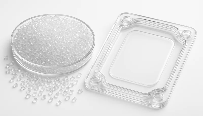
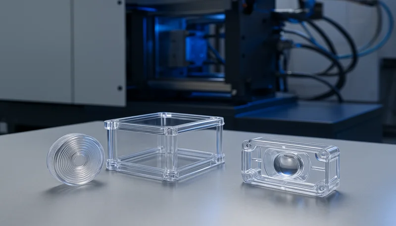
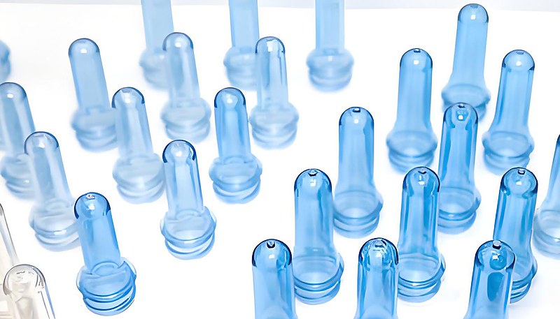
polycarbonate1 injection molding is a processing method that forms PC resin into parts by melting, injecting into a mold, and cooling to achieve final dimensions. The injection molding process2 for PC requires precise control because this amorphous thermoplastic has high impact strength, optical clarity, and heat resistance up to 135°C continuous use. Engineers choose PC when applications demand transparency, toughness, or dimensional stability.
In our Shanghai facility, we process 400+ materials including multiple PC grades—general purpose, flame-retardant, medical, and UV-stabilized variants. Each grade shifts processing windows slightly. We see flame-retardant PC needing slightly higher melt temperatures and longer cycle times due to additive content. Medical-grade PC requires stricter drying and sometimes dedicated drying hoppers to avoid contamination.
The reality: PC is not forgiving. Unlike ABS or PP, small variations in drying time or melt temperature cause visible defects immediately. You get streaks, silvering, or brittle parts after one bad shot. That’s why engineers who succeed with PC treat it as a high-precision process rather than generic thermoplastic molding.
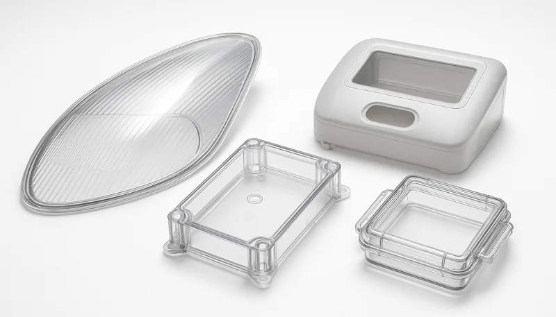
The tradeoff is worth it. PC delivers properties few other materials match—impact strength around 850 J/m notched Izod, light transmission up to 90%, and good resistance to chemicals and flame. That combination makes it the go-to material for automotive headlight lenses, medical device housings, electronic enclosures, and safety glazing.
How Do You Dry PC Before Molding?
Dry PC at 120-150°C for 3-4 hours using desiccant drying equipment before molding. PC absorbs moisture from air and hydrolyzes if processed wet, losing molecular weight and mechanical properties. The moisture content must be below 0.02% before feeding material into the hopper.
Here’s what happens when you skip drying: water reacts with PC chains at processing temperatures, breaking polymer bonds. The result is molecular weight reduction, loss of impact strength, and surface defects like silver streaks or splay. We see this failure mode constantly—new teams rush PC into the machine, get cloudy parts with zero impact strength, and blame the material grade.
Our standard drying protocol uses desiccant dryers at -40°C dew point. For standard PC grades, 120-130°C for 3 hours works. For high-heat or glass-filled PC, bump to 140-150°C for 4 hours. The key is maintaining temperature throughout the hopper, not just at the dryer outlet. Ambient moisture reabsorbs quickly—leaving dried pellets exposed for even 30 minutes can push moisture back up.
Practical tip: use a moisture analyzer or a simple moisture content meter to verify drying before production starts. Don’t rely on dryer setpoints alone. We’ve seen dryers malfunctioning or thermocouples drifting, showing 130°C while actual material temperature is 90°C. That gap costs you one bad batch and lost production time.
For high-volume production, consider hopper dryers with closed-loop moisture sensors. These add cost but prevent the single most common PC failure mode. In 20 years of molding PC, we estimate 70% of first-shot failures trace back to inadequate drying. Fix drying upfront, and half your PC problems disappear.
“PC requires drying at 120-150°C for 3-4 hours before molding.”True
Polycarbonate absorbs moisture from ambient air and must be dried below 0.02% moisture content using desiccant dryers to prevent hydrolysis during melt processing.
“You can dry PC pellets overnight in an ambient oven.”False
Ambient ovens lack controlled dew point and can actually increase moisture content. Desiccant drying at -40°C dew point is required to remove moisture from PC effectively.
What Are Optimal PC Molding Temperatures?
Set melt temperature to 280-310°C and mold temperature to 80-120°C for most PC injection molding applications. The exact melt temperature depends on flow length, part thickness, and PC grade. Mold temperature affects crystallinity and stress levels—higher temperatures reduce residual stress and improve optical clarity.
Starting point: 290-300°C melt, 90-100°C mold for most general-purpose PC parts. If you see incomplete fills or flow marks, increase melt temperature in 5-10°C increments up to 310°C maximum. If you see degradation, discoloration, or gas marks, reduce melt temperature. The window is narrower than for ABS or PP—too cold gives short shots, too hot degrades material rapidly.
Mold temperature is often overlooked but critical for PC. Cold molds (below 60°C) cause high residual stress, warpage, and poor surface finish. Hot molds (above 120°C) extend cycle time and can cause sticking. We run most PC tooling at 90-110°C using circulating oil or cartridge heaters. For optical parts demanding clarity, push mold temperature to 110-120°C.
Temperature ramp-up matters too. Don’t slam material from 20°C to 300°C instantly. Use a gradual profile across the barrel zones to ensure uniform melting. Typical zone settings: rear 260°C, middle 280°C, front 295°C, nozzle 300°C. This gives PC time to stabilize melt homogeneity before entering the mold.
Monitoring is essential. Use melt temperature sensors and periodic viscosity checks to confirm your actual melt temp matches machine settings. We’ve seen barrel thermocouples drift 10-15°C over months of production, causing gradual quality issues that teams struggle to diagnose. Calibrate regularly and verify with a pyrometer if available.
Material grade variations require temperature adjustments too. Flame-retardant PC often needs higher melt temperatures due to flame retardant additives that can reduce flow. UV-stabilized PC may process slightly differently than standard grades. Always consult the material datasheet for recommended temperature ranges from the resin manufacturer, and adjust based on your specific tooling and part geometry.
“PC melt temperatures typically range from 280-310°C.”True
Polycarbonate requires higher melt temperatures than many other thermoplastics due to its high glass transition temperature of approximately 147°C and high melt viscosity.
“Cold molds (below 60°C) improve cycle time for PC.”False
Cold molds increase residual stress and warpage in PC parts, often causing dimensional instability and poor mechanical properties despite shorter cooling times.
How Do You Design Injection Molds for PC?
Proper injection mold design3 for PC requires uniform wall thickness between 1.5-4.0 mm, smooth transitions with 3:1 thickness ratio, adequate draft angles of 1-2°, and generous radii of 0.5-1.0 mm to minimize stress concentrations. Mold surface finish affects optical clarity—mirror polish yields transparent parts, while textured surfaces scatter light for diffuse appearance.
Wall thickness uniformity is non-negotiable for PC. Abrupt thickness changes cause differential cooling, leading to warpage, sink marks, and internal stress. If your design requires varying thickness, transition gradually over a distance at least three times the thickness difference. For a jump from 2mm to 4mm, maintain a ramp of at least 6mm transition length.
Gate design deserves attention. PC has high viscosity, so gate size matters more than for lower-viscosity resins. Use edge gates of 1.0-1.5mm thickness for parts up to 3mm wall thickness. Submarine or tunnel gates of 0.8-1.2mm diameter work for smaller parts. Hot runners are excellent for PC—they reduce material waste and provide better temperature control, but require higher upfront investment.
Ventilation is critical. PC produces more gas than some other resins, especially if slightly overdried or if processing near the upper temperature limit. Provide adequate venting in the mold—0.02-0.04mm vent depth, spaced every 50-80mm along the parting line. Poor venting causes burn marks, gas traps, and incomplete fills even with correct injection parameters.
Ejector design requires care. PC parts can be stubborn and mar easily. Use ejector pins of at least 5mm diameter with smooth, rounded ends. Add stripper plates or air ejection for large, flat parts. Polish ejector pins and ensure no sharp edges contact visible surfaces—PC will show every imperfection. Consider using parting line venting integrated into ejection design to improve gas escape during fill.
Cooling channel design affects warpage and cycle time significantly. Uniform cooling reduces internal stress and prevents warpage. Design cooling channels to follow part contours when possible—conformal cooling is ideal but expensive. If conformal cooling isn’t feasible, ensure cooling channels are evenly distributed and sized appropriately for heat load. Water temperature control within ±2°C helps maintain dimensional stability.
What Are Common PC Molding Defects?
Common PC injection molding defects include silver streaks and splay from moisture, stress whitening and cracking from residual stress, warpage from non-uniform cooling, discoloration from thermal degradation, and sink marks from poor packing. Each defect has a specific root cause and requires targeted corrective action.
Silver streaks or splay appear as wavy silver lines on the part surface. This almost always indicates moisture in the material. Even if you dried for 3 hours, verify moisture content is below 0.02%. Check dryer function, ensure hopper lids are closed, and prevent material from sitting exposed to ambient air. We see this constantly—dryers set correctly but operators leave the hopper lid open for hours.
Stress whitening appears as milky patches when parts are bent or impacted. This indicates high residual stress from cooling too quickly or from improper ejection. Increase mold temperature by 10-20°C to reduce stress. Check for undercuts or sharp features causing high ejection forces. Ensure adequate packing but avoid overpacking, which locks stress into the part.
Warpage and dimensional instability trace back to non-uniform cooling or wall thickness variation. Check cooling channel layout—ensure uniform cooling across the part. If wall thickness varies unavoidably, adjust packing and cooling times to compensate. Sometimes adjusting gate location or adding flow leaders helps balance cooling rates across the part. Increasing mold temperature can also reduce residual stress and improve dimensional stability.
Discoloration—yellowing or browning—indicates thermal degradation. Reduce melt temperature by 5-10°C. Check barrel residence time—ensure you’re not holding molten material too long between cycles. Look for dead spots in the barrel or screw where material stagnates. If using regrind, limit to 25-30% maximum and ensure it’s thoroughly dried. Also check for contamination—foreign materials or cross-contamination from other resins can cause color changes.
Flow marks and weld lines also plague PC parts, especially with long flow lengths or complex geometries. Flow marks appear as visible lines where material fronts meet. Weld lines occur where material flows around an obstacle and rejoins. These can be weak points structurally. Optimize gate location to minimize flow length, consider multiple gates for large parts, and increase melt temperature to improve flow merging. Surface finish helps hide minor flow marks—textured surfaces conceal these defects better than glossy finishes.
“Silver streaks in PC parts usually indicate insufficient drying.”True
Moisture in PC vaporizes at melt temperatures, creating gas bubbles that appear as silver streaks on the part surface. Proper desiccant drying eliminates this defect.
“Higher mold temperature always reduces cycle time.”False
While higher mold temperature reduces residual stress and improves part quality, it increases cooling time and extends cycle time. The optimal mold temperature balances quality and efficiency.
How Do You Optimize PC Processing Parameters?
Optimize PC processing by setting injection speed to medium-fast for filling, using a packing pressure of 50-80% of injection pressure for 2-4 seconds, maintaining cooling time based on wall thickness at approximately 10-12 seconds per mm, and back pressure of 50-150 bar to improve melt homogeneity. Screw speed of 50-100 RPM provides adequate mixing without excessive shear heating.
Injection speed affects part quality significantly. Too slow causes material to freeze prematurely, resulting in short shots or weld lines. Too fast causes jetting, high shear heating, and potential degradation. Start at medium speed and adjust based on part appearance. For thin-walled parts needing long flow, push speed higher. For thick parts where flash is a concern, reduce speed.
Packing pressure compensates for shrinkage as the material cools. PC has relatively low shrinkage (0.5-0.7%), but packing still matters for dimensional accuracy. Start packing at 60% of injection pressure for 3 seconds, then adjust. Too little packing causes sink marks and dimensional undershoot. Too much packing creates flash, high residual stress, and can even cause ejection problems.
Cooling time depends primarily on wall thickness but also on mold temperature. A rough guideline: 10-12 seconds per mm of wall thickness for PC. A 3mm wall needs roughly 30-36 seconds cooling time. Increase this for thicker sections or parts requiring high dimensional precision. Use infrared temperature probes or thermal imaging to verify the part is solidifying evenly.
Screw recovery and back pressure affect melt quality. Use back pressure of 50-150 bar to improve melt homogeneity and reduce air entrapment. Keep screw speed moderate—50-100 RPM—to avoid excessive shear heating that can degrade PC. Ensure shot size is 20-30% of barrel capacity to maintain consistent melt temperature between shots.
“PC shrinkage is typically 0.5-0.7%.”True
Polycarbonate exhibits relatively low shrinkage compared to semi-crystalline materials, but packing and cooling parameters still critically affect final dimensions and stability.
“Higher back pressure always improves part quality.”False
While back pressure improves melt homogeneity, excessive back pressure can cause material degradation, increase barrel temperature, and create color shifts. Optimize back pressure rather than maximizing it.
What Are Typical PC Injection Molding Applications?
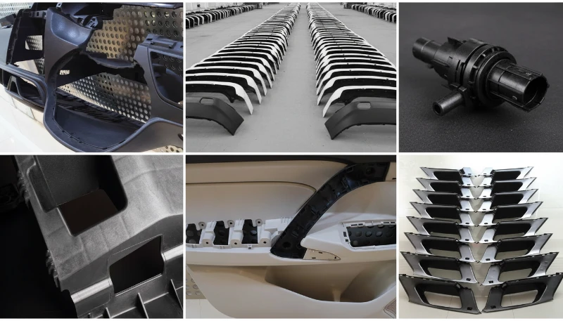
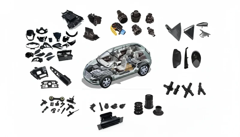
PC injection molding serves automotive headlight lenses and light covers, electronic enclosures and connectors, medical device housings and components, safety glazing and riot shields, optical discs and lenses, and consumer electronics requiring impact resistance and clarity. The combination of optical properties, toughness, and heat resistance makes PC versatile across industries.
Automotive applications dominate PC usage. Headlight lenses, fog light covers, and taillight assemblies require transparency and impact resistance. PC withstands UV exposure (with appropriate stabilizers) and maintains clarity at elevated temperatures under the hood. We mold automotive light components with tight optical specifications—transmission above 88% and yellowness index below 2.0.
Electronics and electrical applications use PC for enclosures, connectors, and components requiring flame retardancy. Flame-retardant PC grades meet UL94 V-0 standards while maintaining mechanical properties. These parts must also resist heat from electronic components and provide electrical insulation. PC’s dielectric strength of 15-20 kV/mm suits many electrical applications.
Medical devices represent a growing PC market. Surgical instrument housings, fluid handling components, and medical equipment enclosures benefit from PC’s toughness, clarity, and sterilization compatibility. Medical-grade PC requires biocompatibility and strict processing control—often requiring dedicated equipment to prevent cross-contamination. Our Shanghai facility operates with ISO 13485 certification for medical device manufacturing.
Frequently Asked Questions
How long does PC need to be dried before injection molding?
PC requires 3-4 hours of drying at 120-150°C using desiccant equipment before molding. The moisture content must reach below 0.02% to prevent hydrolysis during melt processing. Higher drying temperatures (140-150°C) are needed for glass-filled or high-heat PC grades. Never rely on ambient drying or skip drying steps—this is the single most common cause of PC part failure. Use a desiccant dryer with -40°C dew point and verify moisture content with a moisture analyzer before production starts. Even dried PC reabsorbs moisture quickly when exposed to air, so keep hopper lids closed and material sealed.
What is the ideal melt temperature for PC injection molding?
The ideal melt temperature for PC ranges from 280-310°C depending on the grade and part geometry. General-purpose PC typically processes at 290-300°C. Flame-retardant or glass-filled grades may require slightly higher temperatures up to 310°C. Exceeding 310°C risks thermal degradation and discoloration. Start at 290°C and adjust in 5-10°C increments based on part fill appearance and surface quality. Use a gradual temperature profile across the barrel zones to ensure uniform melting without thermal shock. Monitor for signs of degradation like yellowing or gas marks.
What mold temperature is best for PC parts?
Optimal mold temperature for PC is 80-120°C, with 90-110°C being the typical range for most applications. Higher mold temperatures (110-120°C) reduce residual stress and improve optical clarity for transparent parts. Lower mold temperatures (80-90°C) provide faster cycle times but may increase warpage risk. Adjust based on part requirements—optical parts need hotter molds than opaque components. Circulating oil or cartridge heaters provide uniform temperature control for PC tooling. Cold molds below 60°C cause high residual stress and poor surface finish results.
Why do PC parts have silver streaks on the surface?
Silver streaks or splay on PC parts indicate moisture in the material, typically from insufficient drying. Even dried PC can reabsorb moisture if left exposed to ambient air. Ensure desiccant drying at 120-150°C for 3-4 hours with a -40°C dew point dryer. Verify moisture content is below 0.02% before molding. Check dryer function and keep hopper lids closed to prevent moisture reabsorption. Silver streaks are the most visible sign of moisture-related hydrolysis during melt processing. This is the most common PC failure and requires immediate drying verification.
What causes warpage in PC injection molded parts?
PC warpage primarily results from non-uniform cooling, differential wall thickness, or high residual stress. Ensure uniform wall thickness with smooth transitions (3:1 ratio) and adequate cooling channels. Increase mold temperature by 10-20°C to reduce residual stress. Check that cooling time is sufficient for the thickest sections. Sometimes adjusting gate location or adding flow leaders helps balance cooling rates across the part. Warpage often worsens over time if residual stress isn’t managed during molding. Use mold flow analysis to identify potential warpage areas before tooling.
Can PC injection molding produce transparent parts?
Yes, PC injection molding can produce transparent parts with light transmission up to 90%. Transparency requires high mold temperatures (110-120°C), proper drying to prevent splay, and highly polished mold surfaces. The mold surface finish directly transfers to the part—mirror-polished cavities yield clear parts, while textured surfaces create diffuse or translucent appearance. Avoid scratches or imperfections in the mold that will affect optical quality. Use PC grades specifically formulated for optical applications rather than general-purpose resin. Monitor yellowness index to ensure consistent clarity.
What is the shrinkage rate of PC in injection molding?
PC has a typical shrinkage rate of 0.5-0.7%, which is relatively low compared to semi-crystalline materials. The low shrinkage helps dimensional accuracy but does not eliminate the need for proper processing. Packing pressure, cooling time, and mold temperature all affect final dimensions. Use standard shrinkage values for initial mold design but validate actual shrinkage during T1 sampling with the specific PC grade. Different PC grades may have slightly different shrinkage characteristics. Measure shrinkage in flow and transverse directions as they can vary.
Quick rule: Dry PC at 120-150°C for 3-4 hours, run melt at 290-300°C, keep mold at 90-110°C, and maintain uniform wall thickness. If you see silver streaks, check drying. If parts warp, balance cooling. If dimensions drift, adjust packing. Master these basics, and PC becomes a reliable workhorse rather than a problematic material.
In our Shanghai factory with 45 injection molding machines and 20+ years of experience since 2005, we process PC daily across automotive, electronics, and medical applications. Our 8 senior engineers and 30+ English-speaking project managers understand the material’s requirements and can help you optimize your tooling and process for PC parts.
We build 100+ molds per month in our in-house tooling facility, supporting projects from rapid prototyping through full-scale production. Our 400+ material capability includes multiple PC grades, and we maintain ISO 9001 and 13485 certification for quality management and medical device manufacturing.
Ready to mold PC parts with confidence? Get a free quote and technical consultation for your project.
-
polycarbonate: Polycarbonate is an amorphous engineering thermoplastic with outstanding impact strength and optical clarity, typically used for parts requiring high toughness and transparency. ↩
-
injection molding process: Injection molding process is a manufacturing method where molten plastic is injected into a mold cavity under high pressure, cooled, and ejected as a solid part. ↩
-
injection mold design: Injection mold design refers to the engineering process of creating the tooling components and features that determine how plastic parts are formed during the molding cycle. ↩


