 Skip to content

- Edge gates are simplest and most common—ideal for prototypes and low-to-mid volume production where vestige is acceptable.
- Submarine gates self-trim at ejection, eliminating manual degating—useful for automation-friendly tooling.
- Hot tip gates on hot runner systems leave zero vestige—the best choice for appearance surfaces and high-volume runs.
- Fan gates reduce stress on large, flat parts; diaphragm gates ensure uniform fill on cylindrical components.
- Gate choice directly impacts vestige size, cycle time, part stress, and total tooling cost—get it right in DFM.
What Are Injection Mold Gate Types?
An injection mold gate is the narrow passage through which molten plastic flows from the runner system into the mold cavity. Gate type, size, and location are tooling design decisions that affect fill balance, surface quality, part stress, vestige, and ejection. Getting gate decisions right in DFM is cheaper than correcting them after steel is cut. This guide covers the main gate types from a tooling engineering perspective; for the broader process context, see our Injection Molding Complete Guide and for mold design fundamentals, see our Injection Mold Complete Guide.
Choosing the wrong gate type is one of the most expensive mistakes in injection mold design—it often forces you to rework the steel, add a new insert, or scrap first-article samples entirely. Yet many engineers default to the familiar edge gate without evaluating whether it fits their part geometry, resin, or production volume. This guide gives you a structured way to make the right gate decision before cutting steel.
“Gate type and location are finalized in DFM—changing them after T1 samples can cost 3–6 weeks of rework.”True
Gate type affects vestige location, part stress, cycle time, and tooling cost. Unlike process parameters (temperature, speed, pressure), gate geometry is cut into steel—repositioning or changing a gate after first article samples means re-machining cavity inserts, which costs both time and money. Nail it in DFM, before any steel is cut.
“Hot tip gates always leave a perfectly smooth surface with no mark.”False
Hot tip gates leave a small witness mark or dimple at the gate point—typically 0.5–1 mm in diameter. This mark is designed into the part geometry (often a recessed boss or logo area) to make it invisible or acceptable. On fully flat cosmetic surfaces, the dimple can be objectionable.
Gates are broadly classified into two groups: cold-runner gates (where the runner solidifies and is ejected with the part) and hot-runner gates (where the runner remains molten throughout the cycle). Within each group, there are several geometric variants. The right choice depends on your part geometry, resin, appearance requirements, and production volume.
What Is an Edge Gate?
The edge gate (also called a side gate) is the most widely used gate type in injection molding. It sits at the parting line1 of the mold and feeds material directly into the side of the part. The gate cross-section is typically rectangular—1 to 5 mm wide and 0.5 to 2 mm deep, depending on part wall thickness. After molding, the runner and gate are removed manually, leaving a visible vestige of 0.5 to 2 mm on the part edge.
Edge gates are popular for good reasons: they are easy to add, easy to adjust, and straightforward to machine. If your first article sample shows short shots or imbalanced fill, the toolmaker can widen the gate in an afternoon. They work with nearly every thermoplastic resin and suit rectangular or flat parts well. The main limitation is the visible gate vestige—if your part has a cosmetic edge or a precision mating surface on that face, you need a different gate type.
For production volumes up to around 100,000 shots per year, the edge gate is often the lowest-risk and lowest-cost choice. At higher volumes, the secondary trimming labor adds up. One practical rule from our team: if you expect more than 500,000 parts per year and the part has any cosmetic requirement, switch to a submarine or hot runner gate from the start.
How Does a Submarine Gate Work?
A submarine gate works by using a tapered tunnel angled 30–45 degrees below the parting line; when the mold opens and the part ejects, the gate automatically shears at its narrowest point—eliminating manual trimming and leaving a vestige of less than 0.1 mm. Also called a tunnel gate or chisel gate, this design feeds material through a curved channel that enters the part from the side or base.
Submarine gates cost more to machine than edge gates—the angled tunnel requires EDM or careful CNC work—but they save labor on every shot. For a 1-million-shot production run, eliminating 2 seconds of trimming time per part saves more than 500 hours of labor. They are especially useful when the gate needs to be hidden on an underside or inside face of the part.
“Submarine gates eliminate secondary trimming operations entirely, reducing cost-per-part at high volume.”True
The auto-shear mechanism of a submarine gate is built into the tool geometry—no operator action required. For a 500K/year production run with a 2-second manual trim, switching to a submarine gate recovers roughly 278 machine-hours per year. The break-even on the extra EDM cost is typically reached within the first 100,000 parts.
“A larger gate always produces a better part.”False
Oversized gates increase cooling time—the thick gate slug cools slowly—and create larger vestiges requiring more trimming. Gate sizing is a balance: wide enough to fill and pack the cavity, narrow enough to freeze promptly. Our starting point: gate depth = 50–80% of part wall thickness.
Submarine gates are commonly used with ABS, PP, HIPS, and other materials that shear cleanly. Brittle or glass-filled materials can crack at the gate during ejection, making submarine gates a poor choice for those resins. The gate location must be carefully chosen: the submarine tunnel must clear ejector pins and other mold features. Our DFM analysis process always checks submarine gate feasibility in the first review session—repositioning a submarine gate after steel is cut means re-machining a significant section of the cavity insert.
What Are Pin Gates and Hot Tip Gates?
Pin gates are small circular gates—typically 0.5 to 1.5 mm diameter—used with three-plate molds in cold runner2 systems. The three-plate design allows the runner to separate from the part automatically when the mold opens, making pin gates self-degating. They are commonly used for small parts and multi-cavity molds where the gate needs to feed the center or top of the part rather than the edge.
Hot tip gates are the hot runner equivalent of pin gates. A heated nozzle tip sits directly against the cavity, injecting plastic through a 0.5–1.5 mm orifice without any runner or cold slug. When the nozzle retracts, it leaves virtually zero vestige on the part surface—often just a small dimple that is designed into the part geometry. Hot tip gates add $800 to $2,500 per gate point to the tooling cost, but they eliminate runner scrap entirely and reduce cycle time by removing the runner cooling phase. For parts running at 500,000+ shots per year, the economics almost always favor a hot runner system with hot tip gates.
“Hot tip gates eliminate runner scrap entirely, reducing material cost per shot.”True
In a hot runner system, the runner channel stays molten throughout production. No runner is ejected, so all plastic shot goes into the part. For engineering resins costing $5–$15 per kg, eliminating a 20g runner per shot saves $100–$300 per thousand parts at scale.
“Any gate type can be easily changed after the mold is built without significant cost.”False
Gate changes after tool construction range from simple to very expensive. Changing from a cold runner to a hot runner requires building a new manifold—a major rebuild costing 40–80% of the original tooling cost. Always finalize gate type during DFM before steel is cut.
When Should You Use Fan Gates and Film Gates?
Fan gates spread the gate width across a large portion of the part edge—sometimes 30–100 mm wide—to create a wide, thin flow front. This reduces linear flow velocity and shear stress3 at entry, which matters for brittle materials like polycarbonate and acrylic, or for very thin-walled parts. The fan shape transitions from the runner width to a wider gate width with smooth, tapered sides to avoid stress concentration.
Film gates (also called tab gates in some texts) are the extreme version of fan gates—they run the full width of the part edge at a uniform thin depth (0.2–0.5 mm). They ensure the most uniform fill front across large flat parts but leave a large vestige that requires trimming. Diaphragm gates are the rotational equivalent: they feed uniformly around the circumference of a cylindrical part, preventing the weld line that would form if the part were fed from one side. Diaphragm gates are mandatory for round components like bushings, tubes, and impellers where a weld line on the ID or OD would compromise part strength.

Multi-point gating—using two or more gates on a single part—is another tool for large flat parts. By gating at multiple locations, you can reduce fill pressure, shorten flow length, and eliminate stress concentration from a single large gate. The trade-off is weld lines at the point where flow fronts meet. Mold flow analysis (Moldflow or Moldex3D simulation) is essential for multi-point gate decisions—it lets you see where weld lines will fall before committing the tool steel.
Which Gate Type Fits Your Project?
The table below summarizes the key trade-offs between the seven main gate types. Use it as a first filter—then validate your choice through DFM review and, for complex parts, mold flow simulation.
| Gate Type | Vestige | Auto-Degateable? | Best For | Tooling Cost |
|---|---|---|---|---|
| Edge (Side) Gate | 0.5–2 mm | No (manual trim) | General purpose, flat/rectangular parts | Low |
| Submarine (Tunnel) Gate | <0.1 mm | Yes (auto-shears) | High-volume, hidden gate locations | Low–Medium |
| Pin Gate (3-plate) | <0.5 mm | Yes (3-plate auto) | Small parts, multi-cavity top-gating | Medium |
| Hot Tip Gate (hot runner) | ~0.3–0.5 mm dimple | N/A (no runner) | High-volume, appearance surfaces | High (+$800–$2,500/gate) |
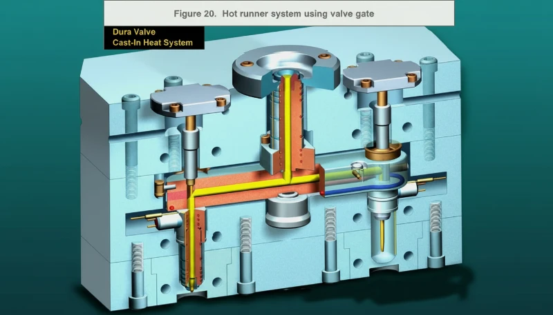
| Valve Gate (hot runner) | <0.1 mm flat mark | N/A (no runner) | Cosmetic surfaces, thick parts | High (+$1,500–$3,500/gate) |
| Fan Gate | Wide vestige | No (manual trim) | Thin-walled, brittle, or clear parts | Low–Medium |
| Diaphragm / Ring Gate | Full-perimeter vestige | No (manual trim) | Cylindrical/tubular parts (no weld line) | Medium |
A few selection rules that hold in most cases: If your part has no cosmetic requirement and runs under 200,000 shots per year, start with an edge gate and optimize later. If the gate location is on a B-surface (hidden face) and your resin shears cleanly (ABS, PP, HIPS), use a submarine gate. If surface appearance is critical anywhere near the gate, use a hot runner with a hot tip or valve gate. If your part is large and flat with thin walls, use a fan gate or multiple hot tip gates based on mold flow analysis results. These rules cover roughly 80% of real-world gate selection decisions.
At our Shanghai facility, we manufacture over 100 injection molds per month across our 45 injection machines (90T–1850T). One pattern we see repeatedly: buyers request an edge gate in their first DFM because it’s familiar, then upgrade to a submarine or hot tip gate after the first trial when they realize the vestige fails their assembly tolerance. Catching this in DFM—before cutting steel—saves 3–6 weeks of rework. Our 8 senior mold engineers run gate location checks as a mandatory step in every DFM review.
Gate sizing is another area where we see costly mistakes in our daily production. When the gate is undersized, we get short shots and high fill pressure; when it’s oversized, cooling time extends and vestige becomes problematic. In our Shanghai workshop, our toolmakers document gate depth as 50–80% of part wall thickness for most amorphous resins—this starting point works for about 70% of projects, then we fine-tune based on T1 trial results.
What Are Common Gate Problems and How to Prevent Them?
The most common gate-related problems are jetting, blush, burn marks, excessive vestige, and premature gate freeze-off—each caused by specific issues with gate geometry, melt temperature, injection speed, or gate location. Preventing them requires precise gate sizing and location adjustments.
Jetting happens when the gate is too small for the cavity size: the plastic shoots through the gate at high velocity and hits the far wall before the cavity fills from the sides, leaving a serpentine mark or wavy pattern on the part surface. Fix: widen the gate or relocate it so the jet hits a wall or core pin immediately. Alternatively, reduce injection speed at the start of fill—many molders switch to two-stage injection speed to fill the gate area slowly and then accelerate.
Blush (a dull, frosted area around the gate) occurs when the gate is too large or the melt temperature is too high—the plastic chills on the mold surface before flowing properly. Fix: reduce gate land length or raise the mold temperature slightly. Burn marks at the gate indicate trapped air heating from compression, or plastic shearing at too high a rate. Check that gate cross-section gives a shear rate below 50,000 s⁻¹ for standard resins.

Gate freeze-off time controls part weight consistency—a gate that freezes too early allows backflow and short shots. The gate must stay open long enough for packing pressure to compensate for volumetric shrinkage as the part cools. If the gate freezes before packing is complete, the cavity underfills and part weight drops shot-to-shot. The solution is either to increase gate cross-section, increase melt temperature, or increase packing time.
Gate blush on textured surfaces occurs when plastic shears against the gate land at wrong speed—too fast creates a frosted halo. The fix is two-stage injection speed: slow through the gate, fast once clear of the gate land. For textured surfaces, gate land length of 0.5–1mm reduces shear contact area. Document gate land geometry in your tool spec from the start; it is the hardest dimension to modify after T1.
Frequently Asked Questions
What is the most common injection mold gate type?
The edge gate (side gate) is the most widely used gate type in injection molding. It sits at the parting line of the mold and is straightforward to machine, adjust, and repair. It works with almost all thermoplastic resins and part geometries. The main limitation is the visible vestige it leaves on the part edge—typically 0.5 to 2 mm—which must be trimmed manually. For high-volume production or parts with cosmetic edge requirements, engineers often upgrade to submarine or hot-runner gates after initial trials.
What is the difference between a submarine gate and an edge gate?
Both edge gates and submarine gates are cold-runner gates, but they differ in location, appearance, and degating method. An edge gate sits at the parting line and requires manual trimming after ejection, leaving a vestige of 0.5–2 mm. A submarine gate is machined as an angled tunnel below the parting line; when the part ejects, the gate automatically shears, leaving a vestige of less than 0.1 mm. Submarine gates cost more to machine but eliminate secondary trimming operations, making them the better choice for high-volume production of 100,000 parts or more per year.
When should I use a hot runner gate instead of a cold runner gate?
Hot runner gates become economically justified when production volume exceeds approximately 200,000–500,000 shots per year, or when the part has cosmetic requirements near the gate location. Hot runner systems eliminate runner scrap (saving material cost), reduce cycle time (no runner cooling phase), and allow gate locations on non-parting-line surfaces. The added tooling cost—typically $3,000–$15,000 depending on the number of gate drops and manifold complexity—is recovered through material and cycle time savings within one to two production years at high volume.
How do I choose between a hot tip gate and a valve gate on a hot runner?
Both are hot runner options, but valve gates provide a cleaner cosmetic result. A hot tip gate leaves a small dimple of 0.3–0.5 mm. A valve gate uses a mechanical pin that closes before the plastic freezes, leaving an even flatter mark. Valve gates cost $700–$2,000 more per drop and require maintenance of the valve pin actuator. Choose hot tip when a small dimple is acceptable; choose valve gate when the surface must be perfectly flat.
Can I change the gate type after the mold is built?
Gate changes after tool construction range from simple to very expensive depending on the type of change. Widening an edge gate or deepening it is a simple steel-removal operation—usually one to two hours of machine time. Changing from a cold runner to a hot runner requires building a new manifold and drilling new channels—a major rebuild costing 40–80% of the original tooling cost. Relocating a submarine gate involves filling the old tunnel with a steel insert and remachining the new location. Always finalize gate type and location during DFM, before T1, to avoid costly rework.
What gate type works best for glass-filled nylon or other glass-filled resins?
Glass-filled resins are abrasive and brittle at the gate shear point, which rules out submarine gates—glass fibers crack at the auto-shear point during ejection. Edge gates with hardened tool steel (H13 or S136) at the gate land are standard. The gate must be sized for lower shear rates to minimize fiber breakage and reduce wear. Hot runner valve gates are excellent at high volume because the valve pin closes positively. Fan gates work well for large flat parts in glass-filled nylon to spread shear load and reduce fiber orientation.
- Under 200K shots/year + no cosmetic requirement? Start with an edge gate.
- Gate must be on a hidden face + resin shears cleanly (ABS, PP, HIPS)? Use a submarine gate.
- Cosmetic surface anywhere near the gate? Hot runner with hot tip or valve gate—no exceptions.
- Large flat panel or thin-walled part? Fan gate or multi-point hot runner; validate with mold flow simulation.
- Cylindrical part (bushing, tube, impeller)? Diaphragm gate to eliminate weld lines on the ID/OD.
In our 20+ years of injection molding experience, we have found that the most expensive gate decision is the one you have to remake after T1 samples. Our Shanghai facility runs 45 machines (90T–1850T) and our 8 senior mold engineers run gate location checks as a mandatory step in every DFM review. If you need help selecting the right gate type for your part, our engineering team is ready to assist. Request a free DFM review and gate location analysis — our 8 senior engineers will review your 3D CAD file and recommend the optimal gate design within 24 hours.
-
parting line: The parting line is a defined seam on a molded part that marks where the two halves of the injection mold meet and separate, visible as a thin line on the finished part surface. ↩
-
cold runner: A cold runner is a channel system that delivers molten plastic from the injection machine nozzle to the mold cavity, where the runner solidifies with each shot and is ejected along with the molded part. ↩
-
shear stress: Shear stress in injection molding refers to the internal force per unit area exerted on molten plastic as it flows through narrow passages such as gates and runners. Excessive shear stress degrades polymer chains and causes surface defects like splay or blush. ↩


