 Skip to content

Introduction:Injection molding relies on a precision injection mold to produce high-volume parts with consistent quality. But what if you need prototype tooling1 fast, without the cost and lead time of steel molds?
However, conventional mold making can be both time-consuming and costly, particularly for small or custom production runs. 3D printing2 offers a cost-effective solution that slashes lead times from weeks to days. For teams comparing rapid-prototyping suppliers, our supplier sourcing guide explains how to qualify a molding partner before committing to printed tooling.
In this article, we will walk through the complete process of creating 3D printed molds for injection molding—from CAD design to printing, mounting, and running your first shots. We will also share practical lessons from our own tooling floor to help you decide when printed molds make sense and when they do not.
- 3D printed molds cut tooling lead time from weeks to days, ideal for low-volume prototyping
- SLA and DLP resins offer the best surface finish and dimensional accuracy for printed molds
- Typical 3D printed molds survive 10–100 shots depending on material, geometry, and injection pressure
- Always include draft angles (≥1°), uniform wall thickness, and proper vent channels in your mold design
- For production volumes above a few hundred parts, traditional steel molds are still the better investment
What Should You Know Before Choosing a 3D Printed Injection Mold?
A 3D printed injection mold is a fast prototype tool with strict process limits. Before choosing one, verify shot count, draft, part size, resin temperature, injection pressure, and whether the printed insert can survive the expected molding window.
Print Runs: It’s important to note that 3D printed injection molds, while cost-effective and efficient for low-volume production, have lower structural integrity compared to metal molds. Typically, these molds are viable for 30 to 100 runs, making them ideal for rapid prototyping purposes. For larger production volumes, traditional aluminum or steel molds may be more suitable.
draft angle3: Add practical draft so the molded part releases without tearing the printed cavity or forcing the operator to pry the part out. A common starting point is 1 to 2 degrees per side, with deeper ribs, textured surfaces, or flexible materials often needing more draft after DFM review.
Size and Shape: Understanding the dimensions of the desired injection molded part is crucial when selecting the appropriate size and shape of the mold. Notably, 3D printed molds differ from CNC machined molds in terms of size, typically being smaller in scale. This size difference impacts the range of injection molded parts that can be produced using 3D printed molds compared to CNC machined counterparts.
“3D printed molds can produce functional injection-molded parts in less than 24 hours from design completion.”True
True — with SLA resin molds and a well-tuned injection machine, you can go from CAD to first shots within a single day. However, mold life is limited to roughly 10–100 cycles depending on geometry and pressure.
“Any desktop FDM printer can produce production-quality injection molds.”False
False — while FDM is the most affordable option, layer lines and porosity limit mold quality. Resin-based SLA and DLP printers produce significantly smoother, more dimensionally accurate molds suitable for low-volume runs.
In our Shanghai factory, rapid prototype molds still have to match production constraints: ZetarMold has 20+ years of tooling experience, an in-house mold manufacturing facility, and 47 injection molding machines from 90T to 1850T, so printed inserts are reviewed against real press, material, and mold-maintenance limits before trial molding.
Completed Flawlessly: The surface integrity of 3D-printed molds is occasionally inferior to that of metal injection molds due to the detrimental impact of high injection molding temperatures on mold performance. Consequently, these molds are not the optimal selection for projects necessitating a refined finish. Opting for an aluminum or steel injection mold is a superior alternative.
Alternatively, employing a shielding coating comprised of materials like ceramic on the printed mold can mitigate thermal degradation and aid in attaining a polished finish.
How Do You Create a CAD Design for a 3D Printed Mold?
The initial step in creating a 3D printed mold for injection molding is to design the mold using computer-aided design (CAD) software. Factors that should be considered during the design process include part geometry, molding material, gate location, and cooling channels.
To alleviate design challenges when creating a 3D printing mold, several tips can be beneficial. Firstly, selecting the appropriate mold material is critical. It is essential to ensure that the material chosen is robust and rigid enough to withstand the pressure generated during the injection process. Moreover, the mold’s melting point should exceed the melting point of the injection molding material.
Secondly, meticulous mold design is imperative for successful mold manufacturing. The inner surface of the mold should be positioned in a manner that prevents contact with the print carrier. Incorporating vents in the mold design can aid in the elimination of trapped air during the injection molding process, thereby reducing defects like porous parts. Additionally, integrating cooling channels into the mold design will facilitate a reduction in cooling time.
When designing your part, also consider incorporating a draft angle. Ensuring uniform wall thickness in formed parts and avoiding sharp corners are crucial factors to keep in mind. Injection molding flash is another important consideration; this occurs when extra material extrudes from the parting line of the extrusion die. To eliminate burrs, it’s recommended to include a runner system in the mold design. Moreover, post-design adjustments may be made, such as increasing clamping force and/or reducing injection pressure.
How to Design a 3D Printed Mold for Injection Molding?
A good 3D printed mold design is a supported insert built around draft, venting, gate strength, and controlled ejection. Start with material strength, parting-line support, wall thickness, and a rigid frame so the cheaper tool still produces useful trial data.
Numerous materials can be used for producing 3D printing injection molds, including PETG, ABS, nylon, PP, and acetal. When selecting the material for your 3D printing plastic mold, it’s crucial to consider the following two aspects:
Strength and Stiffness: Plastic polymers suitable for 3D printing injection molds need to exhibit strength and stiffness post-printing. These qualities are vital for enabling the mold to endure the stress generated during the injection process.

Temperature Resistance: As injection molding operates at elevated temperatures to facilitate optimal flow of molten plastic, it is imperative that the plastic material chosen for mold creation possesses a melting point higher than that of the injection molding material.
Mold Design: Strive to enhance dimensional accuracy by factoring in machining allowances on the mold for subsequent post-processing and resizing. Generate a series of molds to assess dimensional discrepancies and incorporate these variations into the CAD model of the molds.
Enhance mold longevity by opening the gate to alleviate pressure within the mold cavity. Ensure one side of the stack mold is flat while utilizing the other side for holding design components. This strategy helps mitigate mold block misalignment and the possibility of overflow.
Incorporate a sizable vent hole from the mold cavity edge to the mold edge for efficient exhaust. This aids material flow into the mold, decreases pressure, and prevents gate area flooding, thereby reducing cycle times. Steer clear of overly thin cross-sections, as surfaces with thickness less than 1-2mm are susceptible to deformation from heat.
Refine your printing process by adjusting the mold back to reduce material usage. Decrease the cross-sectional size of non-mold cavity supporting areas to cut resin expenses and diminish the likelihood of print defects or deformities. Introducing a chamfer can ease the removal of the workpiece from the build platform. Employ centering pins at the corners to align the two prints effectively.
Orientation of the Inner Face: Position the inner mold face to avoid any contact with supports, enhancing print surface quality by minimizing or eliminating support marks. This orientation also reduces the necessity for post-processing.
Shallow Vents: Incorporating vents into the mold design facilitates the removal of trapped air during the injection molding process. The recommended shallow vents, approximately 0.05 mm in size, help reduce the likelihood of defects such as injection flash.
Utilize Channels: Integrate channels into the mold design for molds intended for 20 or more runs. This allows for the inclusion of metal rods and tubes, effectively reducing injection molding defects like warping. Moreover, utilizing channels contributes to a decrease in cooldown time.
Layer Height: Opting for a lower layer height enhances the smoothness of the printed mold and minimizes the visibility of printed lines.
Parts Design: The quality of the injection molding process hinges significantly on the 3D printing mold utilized. Therefore, various factors must be taken into account during the part design phase to ensure the success and efficiency of the printed product, including the incorporation of a draft angle. A recommended draft angle of 20 simplifies the removal of the injection molded part from the printed injection mold.
Material Selection: The choice of material for the 3D printed mold is critical. It should be capable of enduring the elevated temperatures and pressures involved in the injection molding process without warping or melting. Materials like nylon, ABS, and polycarbonate are frequently employed for 3D printing injection molds.
Uniform Wall Thickness: Injection-molded parts require consistent wall thickness to minimize defects such as warping during and after injection. In cases where thin walls are necessary, incorporating thin ribs and gussets can enhance wall strength.
“Printed molds need production-style DFM checks.”True
This is true because wall thickness, radii, draft, venting, and gate support determine whether a low-cost printed insert generates useful molding data or only a failed trial.
“Release agent cannot fix a weak mold design.”False
This is false because release compound helps demolding, but it cannot correct poor parting-line fit, inadequate draft, weak cavity walls, or a printed insert that deforms under injection pressure.
Avoid Sharp Corners: I have included radius on the edges of the mold to eliminate sharp corners. This adjustment helps to facilitate the smooth flow of molten plastic and reduces the occurrence of injection molding defects.
Prevent Flash: Flash is a common issue in injection molding, where excess molten plastic escapes the mold and solidifies during the injection process. This defect can result from a poor fit between mold halves, excessive injection pressure, or mold overfilling.
Flash from 3D printed molds can be eliminated by incorporating runner systems into the mold design and ensuring tolerances on part lines. However, if these methods don’t work, you can try making post-design adjustments, such as increasing the clamping force and/or reducing the injection pressure.
Use Release Compound to Remove Parts: A release agent is introduced during the demoulding process to aid smooth removal of the injection-molded part. Without a release agent, parts can get stuck in the mold. This will require excessive force to remove the part, which may damage the part and/or the mold.
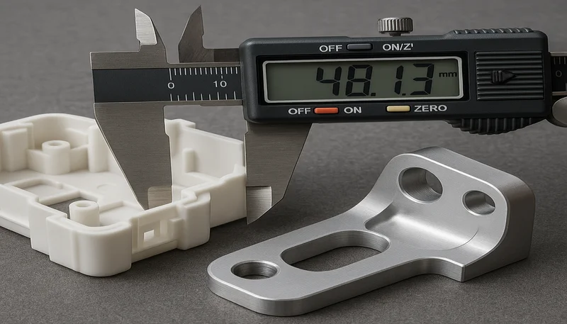
Testing and Verification: Before using a 3D printed mold for injection molding, its performance must be tested and verified. Testing can help identify any issues with mold design or material selection and make necessary adjustments before part production begins.
How Do You Export CAD Design Files for 3D Printing?
CAD export is the step that turns the final mold geometry into a printable STL or 3MF file. Check units, mesh quality, wall thickness, orientation, and tolerance before slicing so the printed insert is accurate enough for molding trials.
What 3D Printing Technologies Work Best for Injection Molds?
Once the STL file is prepared, a 3D printer can be used to produce the injection mold. Molds can be created through various 3D printing processes, such as Fused Deposition Modeling (FDM), Stereolithography (SLA), Selective Laser Sintering (SLS), and Digital Light Processing (DLP). The selection of the 3D printer and printing materials depends on factors like the complexity of the mold and the mold’s longevity.
FDM typically presents the most cost-effective 3D printing solution for plastic molds and tooling. Nevertheless, the final mold may exhibit visible layer lines that necessitate sanding or chemical finishing for removal.
Resin-based 3D printing technologies like SLA and DLP are popular choices as they yield molds with smoother surface finishes, reducing the need for extensive post-processing. Material jetting, another resin-based 3D printing method, can craft molds with superior surface finishes using various materials and colors. SLS utilizes reinforced nylon for mold production, offering robust strength and high surface quality.
“For prototyping under 100 parts, 3D printed molds can be 90% cheaper and 80% faster than traditional steel tooling.”True
True — a printed mold might cost $50–$200 and take 1–2 days, while a steel mold for the same geometry could cost $5,000–$20,000 and take 4–8 weeks. The trade-off is durability and part consistency.
“3D printed molds can withstand the same injection pressures as aluminum or steel molds.”False
False — 3D printed molds typically handle 200–500 bar, whereas production steel molds can endure 1,000+ bar. You must reduce injection pressure and speed when using printed tooling.
What Are the Standard Configurations for 3D Printed Molds?
The standard configurations for 3d printed molds are the main categories or options explained in this section. 3D printing molds for injection molding mainly have the following two standard configurations.
Furnished 3D Printing Mold
This setup does not necessitate aluminum support frames since they are entirely printed. As a result, the mold demands more printing material, escalating both the printing cost and time. Nevertheless, sans a frame, they are susceptible to defects like warping following extensive use.

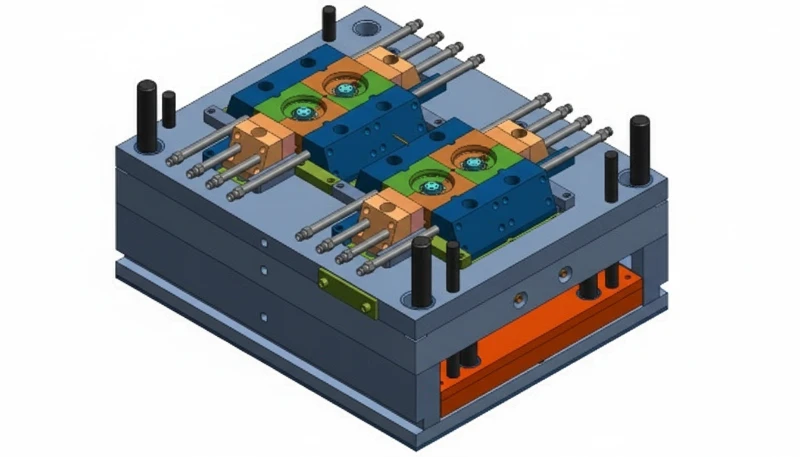
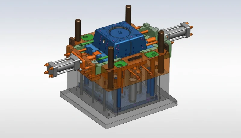
Mount the Mold to the Metal Frame
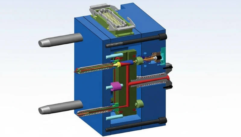
Once the 3D printed mold is complete, it must be mounted into a metal frame (mold base) to hold it in place during the injection molding process. The mold base includes the sprue bushing, where molten material is poured into the mold.
The configuration of the mold determines how it is mounted to the frame. There are two standard configurations of injection molds for 3D printing. The first configuration inserts the printed mold into an aluminum frame, providing stability, accuracy, and support to the mold. This configuration is more suitable for producing precise injection molded parts, helps prevent molding defects such as warping, maintains the integrity of the mold, and ensures consistent pressure distribution during the injection molding process.
The second configuration entails a fully 3D-printed mold without an aluminum frame. Although this removes the necessity for a frame, it necessitates more printing material, leading to increased printing costs and time. Molds created using this configuration are also more susceptible to defects like warping, as support is lacking.
How Do You Start the Injection Molding Process with a 3D Printed Mold?
Starting a printed-mold injection trial is a controlled setup process, not a normal production launch. In our Shanghai factory, we run 47 injection molding machines from 90T to 1850T; our engineers review printed inserts against press tonnage, resin temperature, and mold support, and we found that conservative startup shots make prototype tooling data more reliable.
The startup process is a controlled first-shot sequence for proving the printed insert safely. We mount the printed insert in a rigid frame, verify shutoff contact, confirm the sprue and gate path, and run conservative first shots before increasing pressure. In our factory trials, this staged startup helps separate mold-design problems from process-setting problems.
What Post-Processing Is Required for 3D Printed Molds?
Post-processing is required to make a printed mold smooth, clean, dimensionally usable, and easier to release. This can include sanding to remove layer lines, assembling multiple prints, cleaning supports, checking critical dimensions, and applying a release aid or surface treatment before injection molding trials.
Sanding: Sanding can help eliminate layer lines on the surface of the 3D printed model. Begin with coarser sandpaper and gradually switch to finer grits. Avoid sanding in the same spot for too long to prevent excessive friction and heat that may melt the surface. Be cautious not to sand away too much material, especially around seams if the print needs to be bonded later.
Bonding: When gluing, it is recommended to apply glue in small dots to ensure closer contact between the two surfaces, akin to binding them with a rubber band. For rough or gapped seams, Bondo glue or filler can be used to achieve a smoother finish.
Coloring: During this step, try to do it in a well-ventilated and dust-free area to ensure the coloring is even on all surfaces. When spraying, hang the target while keeping a distance of an arm’s length. After painting the soft glue 3D printing model, allow 1-2 days for it to dry before polishing.
Installing Screw Slots: Installing screw slots can extend the service life of the 3D printed shell. To ensure a tight fit, the holes on the model should be slightly smaller than the screw slots. Secure the model for stability and avoid fast or forceful operations to prevent deformation of the holes.
Silicone Mold Flipping: This process involves a 3D printing mold box, silicone, resin, measuring cup, and other materials. To calculate the mold volume, fill the 3D printing mold box with water first, then pour the water into the measuring cup.
Frequently Asked Questions
How many parts can a 3D printed mold produce?
A 3D printed mold can produce a small validation run or a limited production batch, but the realistic shot count depends on resin temperature, cavity thickness, gate stress, clamping pressure, and cooling time. Some printed inserts only survive a few dozen shots, while well-supported SLA or high-temperature resin molds may run hundreds of cycles. Treat the number as an engineering estimate, not a guarantee, and inspect the cavity, gates, vents, and part dimensions during the trial. Record each shot count and failure mode carefully.
What is the best 3D printing technology for injection molds?
SLA is usually the most practical starting point for 3D printed injection molds because it can produce smoother cavity surfaces and tighter details than many low-cost FDM setups. DLP and material jetting can also work when dimensional accuracy and surface finish are controlled. FDM is useful for fit checks or very rough trials, but layer lines, porosity, and lower heat resistance often create flash, poor surface quality, or early insert failure during actual injection molding. Match the technology to resin and pressure.
Can you use a 3D printed mold for production manufacturing?
A 3D printed mold can support production only when the volume, resin, tolerance, and surface requirements are modest. It is best used for prototype validation, bridge production, and low-volume trials where speed matters more than long tool life. For high-volume programs, abrasive materials, tight tolerances, or cosmetic surfaces, aluminum or steel tooling is still the safer production path because it holds dimensions, cooling performance, and clamping pressure more consistently over many cycles. Use printed tooling to learn before scaling, then lock the production mold specification.
What materials can be injection molded using 3D printed molds?
Lower-temperature thermoplastics are the safest candidates for 3D printed molds. PP, PE, TPE, and selected ABS or nylon grades can be tested when melt temperature, injection pressure, and cycle count stay within the printed insert limits. High-temperature engineering resins, glass-filled compounds, and abrasive materials are much riskier because they can soften, crack, or wear the printed cavity quickly. Always confirm the material data sheet, mold temperature, and expected shot count before committing to printed tooling. Start with conservative processing windows.
How much does a 3D printed injection mold cost?
The cost of a 3D printed injection mold is usually far lower than a CNC-machined production mold, but the exact range depends on insert size, resin type, surface finishing, validation work, and whether a support mold base is required. A simple printed insert can be inexpensive for design validation, while a more durable prototype tool with polishing, assembly, and trial molding costs more. The right comparison is total learning cost: how quickly the mold proves geometry, gating, shrinkage, and part function before production investment.
Do 3D printed molds need post-processing before use?
Yes. Most 3D printed molds need post-processing before injection molding trials. Typical work includes removing supports, cleaning uncured resin, sanding layer marks, checking cavity dimensions, adding vents if needed, and sometimes applying a coating to improve release or reduce porosity. The mold should also be assembled into a rigid support frame so clamping force does not crack the insert. Good post-processing improves surface finish, reduces flash risk, and makes trial data more reliable. Inspect the insert again after the first shots.
When Should You Choose 3D Printed Molds Over Traditional Tooling?
3D printed molds are best when speed, learning, and low-volume validation matter more than long production life. They are useful for prototype trials, bridge tooling, and simple or moderately complex parts where the resin, pressure, tolerance, and surface requirements stay within printed-insert limits.
In essence, the process of creating 3D printed molds for injection molding follows a structured approach. It commences with designing the mold using CAD software and proceeds to fine-tune printer settings to achieve high-quality prints. Subsequent post-processing steps, such as grinding and polishing, may be necessary to enhance the mold’s surface.
Incorporating essential components, like plug-ins, and conducting comprehensive testing ensure functionality and precision. Once validated, the mold is primed for injection molding production, facilitating the rapid prototyping and manufacturing of plastic parts with intricate designs.
Need a quote for your injection molding project?
Get competitive pricing, DFM feedback, and production timeline from ZetarMold’s engineering team.
Request a Free Quote → See our Injection Molding Complete Guide for a comprehensive overview.
-
prototype tooling: Prototype tooling is an early mold or insert used to test part design, material behavior, and process risk before production tooling. ↩
-
3D printing: 3D printing is a layer-by-layer manufacturing method used to build prototype mold inserts from digital geometry. ↩
-
draft angle: Draft angle refers to the taper added to molded part walls so the part can release from the mold without damage. ↩


