 콘텐츠로 건너뛰기

What Is Injection Speed and Why Does It Matter So Much?
Injection speed is the controlled fill velocity that pushes melt into the mold and determines whether parts fill cleanly without burns or flash.
- Injection speed (fill velocity) is the single most influential process parameter for part quality — too slow causes short shots and weld line weakness; too fast causes jetting, flash, and burn marks.
- The optimal injection speed is the fastest speed that fills the cavity without defects — typically 80–95% of maximum machine speed for thin-walled parts.
- Multi-stage speed profiling (variable speed at different screw positions) is the most powerful optimization technique for complex parts.
- Material type determines the appropriate speed range: shear-thinning materials like PP and ABS tolerate high speeds; thermally sensitive materials like PVC and POM require moderated speeds.
- Gate size directly controls local shear rate — smaller gates require lower injection speeds to avoid degradation and jetting.
- Diagnosing speed problems requires connecting observed defects (short shots, jetting, burning, flash, splay) to their specific speed-related root causes.
If you are comparing vendors or planning procurement, our injection molding supplier sourcing guide covers RFQ prep, qualification, and commercial risk checks.
For a broader look at 사출 금형 설계, our pillar guide covers tooling structure, thermal control, and manufacturability tradeoffs.
Injection speed (also called fill rate or injection velocity) is the velocity at which the screw advances to push molten plastic through the nozzle and runner system into the mold cavity, typically expressed in mm/s for screw velocity or cm3/s for volumetric fill rate. It is arguably the single most influential process parameter affecting part quality in 사출 성형—more so than melt temperature or holding pressure for most surface and structural defects. In our factory, injection speed is the first parameter we adjust when troubleshooting cosmetic defects, short shots, or weld line failures, because getting it right creates a wide, stable process window; getting it wrong cascades into multiple quality problems simultaneously.

The physics behind why injection speed matters: plastic melt is a non-Newtonian, shear-thinning1 fluid. Higher injection speeds generate higher shear rates in the gate and runner, which reduce melt viscosity and improve flowability—allowing the material to fill thin sections and long flow paths before freeze-off. But excessive speed also generates viscous (frictional) heating, which can degrade thermally sensitive materials directly at the gate orifice. The balance between improved flow versus thermal risk is the core challenge of speed optimization for any given part. Understanding this tradeoff is essential for every mold and material combination you encounter in production. The table below summarizes how speed changes affect the most common quality outcomes:
| 사출 속도 | Too Slow | Optimal Range | Too Fast |
|---|---|---|---|
| Fill Completion | Short shots, hesitation | Complete, uniform fill | Flash, overpacking |
| Surface Quality | Flow marks, cold slugs | Smooth, consistent finish | Jetting, burning, splay |
| Weld Line Strength | Cold, weak weld lines | Hot, well-knitted weld lines | Degraded polymer at weld |
| Residual Stress | High orientation, warpage | Balanced stress distribution | High shear stress, cracking |
| Mold Wear | Minimal | Normal | Accelerated gate erosion |
How Do You Determine the Starting Injection Speed for a New Mold?
The starting injection speed is found using a rheological fill study. Begin at 20–30% of maximum machine speed, increase in 5–10% steps, and collect a short-shot sample at each speed setting. Inspect each sample part for flash, surface gloss changes, jetting, or short shots—these are the four primary defect indicators that signal you have exceeded the speed envelope. The optimal speed is the lowest speed that fills the cavity completely without any defects—then add 5–10% as a safety margin to account for material batch viscosity variation and slight mold temperature fluctuations. Record this speed as the baseline for production qualification documentation.
“The optimal injection speed for most thin-walled parts is 80–95% of the machine’s maximum injection velocity.”True
Thin-walled parts (wall thickness <1.5 mm) have very short freeze windows—often less than 0.3–0.5 seconds. Filling the cavity at high speed (80–95% of machine maximum) is essential to complete fill before the flow front freezes. Slower speeds cause short shots or hesitation marks in thin-wall applications.
“Slower injection speed always produces better part quality by reducing shear stress.”False
Slower injection speed causes the flow front to cool more rapidly, increasing freeze-off risk in thin sections, creating cold weld lines, hesitation marks, and potentially incomplete fill. The shear-thinning nature of plastic melt means that higher speeds actually reduce viscosity and improve flow through thin walls. Optimal speed is part- and material-specific—rarely the slowest available.
What Role Does Material Type Play in Injection Speed Selection?
Injection speed selection is determined primarily by material type, because each polymer responds differently to shear. Shear-thinning materials like PP and ABS can be filled at 80–100% of machine speed—viscosity drops under shear, improving flow without excessive pressure. Thermally sensitive materials (PVC, POM, TPU) need moderated speeds to prevent heat degradation at the gate. Fiber-filled grades (30–50% GF-PA, GF-PC) require controlled speeds to avoid gate erosion and fiber orientation defects. Amorphous resins like PC and PMMA are particularly vulnerable to speed-induced birefringence in optical parts.
| 재료 | Recommended Speed Range | Key Concern |
|---|---|---|
| PP (polypropylene) | : 사출 단계의 지속 시간은 스크류가 전진하기 시작할 때부터 캐비티가 부피적으로 가득 찰 때까지입니다. 최적의 충전 시간은 일반적으로 부품 크기와 벽 두께에 따라 0.5초에서 3초 사이입니다. | Tiger striping at very high speed |
| ABS | Medium–High (40–80 mm/s) | Burning at gate if too fast |
| PC (polycarbonate) | Medium (30–60 mm/s) | Jetting, splay if too fast |
| PA (nylon) | High (50–90 mm/s) | Flash at parting line if too fast |
| POM (acetal) | Medium (30–60 mm/s) | Thermal degradation, gas marks |
| PVC (rigid) | Low–Medium (20–50 mm/s) | HCl gas release if oversheared |
| Glass-filled PA/PC (30%+) | Medium–High (40–70 mm/s) | Fiber orientation, gate erosion |
What Is Multi-Stage Injection Speed Profiling and When Should You Use It?
Multi-stage injection speed profiling means programming the injection unit to change speed at predefined screw positions during the fill stroke. A typical profile might be: Stage 1 (0–30% fill) at high speed to rapidly fill the runner and gate area; Stage 2 (30–80% fill) at optimal fill speed for the main cavity; Stage 3 (80–100% fill) at reduced speed as the flow approaches cosmetic surfaces, weld lines, or thin features where controlled deceleration improves surface quality. This technique allows the process to be fast where fast is beneficial and slow where slow is necessary—something impossible with single-speed injection.
We use multi-stage injection on virtually every complex part in our facility. A specific example: a large automotive interior trim panel with a highly polished A-surface required injection at 70 mm/s through the gate and main runner (to prevent hesitation marks), dropping to 25 mm/s as the flow front approached the polished cosmetic surface (to eliminate jetting and shear marks), then transitioning to pack pressure at 95% fill completion. Without the speed profile, we could not achieve both complete fill and acceptable surface quality in the same shot.
In our Shanghai factory, we run 47 injection molding machines from 90T to 1850T, so injection speed optimization is not treated as a one-setting recipe. During first trials, our engineers compare short-shot progression, gate shear marks, cavity filling balance, and post-molding dimensional checks before locking the speed profile. That factory routine matters because the same resin can need different fill speeds when gate size, wall thickness, or mold temperature changes.
“Reducing injection speed just before V/P switchover2 improves pack pressure distribution in parts with thick sections.”True
Decelerating the injection speed in the final 5–10% of fill stroke (approaching switchover from velocity to pressure control) reduces inertia effects and allows the machine control system to switch smoothly. Abrupt V/P switchover at high velocity causes pressure spikes that can cause flash, overpack, or part ejection problems in thick sections.
“Multi-stage injection speed profiling is only necessary for cosmetic consumer products.”False
Multi-stage speed profiling is valuable for structural and functional parts as well as cosmetic ones. It is used to control weld line strength (slow down at weld line locations to increase melt temperature at the knit), manage fiber orientation in filled materials, prevent overpacking in thin sections, and eliminate gate-area jetting in functional components regardless of visible surface requirements.
How Does Gate Size and Design Affect Injection Speed Selection?
Gate size determines the local shear rate3 at the gate orifice—this is the single most critical constraint on injection speed for any given mold. For a given volumetric fill rate, a smaller gate produces much higher shear, which can degrade the polymer, cause discoloration, and generate jetting into the cavity. The general rule: reduce injection speed proportionally as gate cross-section decreases. A gate with 50% of the runner area typically requires 70–80% of the speed used with a full-width edge gate. Understanding this relationship is essential before setting any speed parameter, because the wrong speed-gate combination produces defects that cannot be corrected by adjusting temperature or pressure.
When you increase injection speed, monitor for gate-area discoloration (burning), splay, or jetting—the gate degrades first. If gate cross-section is less than 30% of runner area, reduce speed by at least 20%. Submarine gates with angled lands need another 10–15% reduction. Pin gates under 1.5 mm on three-plate molds typically run at 40–60% of standard edge gate speed. Hot runner valve gates tolerate higher speeds because the gate opens mechanically. Gate geometry also affects weld line quality: faster injection raises weld temperature for better diffusion, but only if gate shear stays within material limits.

The gate shear rate can be calculated from the volumetric fill rate and gate cross-section dimensions. For most amorphous resins, maximum allowable gate shear rate is 50,000–100,000/s; for crystalline materials like PA66, it can reach 100,000–200,000/s. Exceeding these limits causes thermal degradation, silver streaks, or gas burns at the gate. In practice, start with a moderate speed that keeps gate shear around 40–60 percent of the material limit, then increase while monitoring for flash or discoloration. A smaller gate forces you to choose between higher speed for pack pressure and lower speed for gate integrity — this is where multi-stage profiling becomes essential.
Use a slow initial speed to pass through the gate smoothly, then ramp up to fill the cavity before freeze-off. This staged approach lets you maintain gate integrity while still achieving complete fill — a technique we apply daily on thin-wall parts where gate freeze time is critical.
How Do You Diagnose Injection Speed Problems in Production?
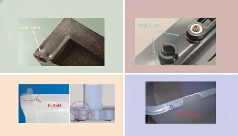
Short shots and hesitation marks mean speed is too low — increase fill velocity until the cavity fills completely before the gate freezes. Jetting, which appears as snake-like serpentine marks streaming from the gate, means speed is too high — slow down or use a larger gate. Burn marks or splay near the gate area usually indicate that injection speed is generating excessive shear heat at a restriction point in the process. Flash along the parting line can mean speed is too fast at the end of fill, packing pressure is too high, or the mold is worn.
Sink marks on the opposite side of thick sections suggest you need faster injection speed to pack more material before the section solidifies. Each of these defects points to a different speed adjustment direction, so identifying the correct symptom is half the solution.
Each of these defects points to a different speed adjustment direction, so identifying the correct symptom is half the solution.
Modern process monitoring systems provide real-time cavity pressure curves and screw velocity profiles that make speed diagnosis faster and more reliable than trial-and-error. In our facility, we rely on cavity pressure sensors and shot-to-shot analytics to detect even subtle speed drift before it affects part quality. When diagnosing, always check the transfer position first. If the machine switches from velocity control to pressure control too early or too late, the effective fill speed changes even if the setpoint has not moved. A common mistake technicians make is assuming a speed problem when the real culprit is a worn check ring allowing melt to leak back during injection — this reduces actual fill speed regardless of what the machine display reads.
A practical diagnostic workflow that works across machine brands: first verify hydraulic pressure and back pressure are within spec, then run a short shot study at 10 speed increments from 20 percent to 100 percent of maximum. Record fill time, peak cavity pressure, and part weight at each step. The speed zone where fill time drops sharply without surface defects is your optimal window. Document this range in your process sheet—operators can reference it during production to catch speed drift early without waiting for quality rejects to pile up.
자주 묻는 질문
자주 묻는 질문
What is the difference between injection speed and injection pressure?
Injection speed is the velocity at which the screw pushes melt into the mold (mm/s or cm3/s), while injection pressure is the hydraulic or electric force driving that movement (bar or MPa). During fill, the machine operates in velocity control—maintaining the set speed regardless of pressure, up to the machine’s maximum pressure limit. At V/P switchover, control shifts to pressure mode for packing and holding. Speed and pressure are related but independently controllable on modern machines, and understanding their distinct roles is essential for process optimization.
What happens if injection speed is too high for the material?
Excessive injection speed causes shear-induced heating at the gate and runner, leading to polymer degradation such as yellowing, burning, jetting across the cavity, splay or silver streaks from volatilized degradation products, and in extreme cases, charred black spots or complete material breakdown. Thermally sensitive materials like POM, PVC, and PMMA are most vulnerable to overspeed damage. Even with robust materials, excessive shear rates cause molecular chain scission that reduces mechanical properties and creates long-term reliability risks in the finished molded part.
How does wall thickness affect injection speed?
Thinner walls require faster injection speeds to fill before freeze-off. The relationship is approximately: fill time ≤ (wall thickness squared) × (material-specific constant). For a 1 mm wall in ABS, fill time must be under 0.3–0.5 seconds; for a 3 mm wall, fill can take 1–3 seconds. Thin-wall molding (under 1 mm) often requires injection speeds exceeding 90% of machine maximum. Conversely, thick-wall parts can tolerate slower speeds, but must balance speed against cosmetic requirements and weld line quality at flow fronts.
Can injection speed affect shrinkage and warpage?
Yes, injection speed significantly affects both shrinkage magnitude and warpage behavior in molded parts. Higher injection speeds create greater shear-induced molecular orientation in the polymer melt, which leads to anisotropic shrinkage—meaning significantly more shrinkage occurs in the flow direction than perpendicular to it. This differential shrinkage is a primary cause of warpage in flat parts, especially with semi-crystalline materials like PP, PE, and PA where crystallization behavior amplifies the effect. Balancing injection speed with gate placement, pack pressure, and cooling time is essential to minimize differential shrinkage and produce dimensionally stable parts consistently across production runs.
Should I adjust injection speed or melt temperature first when troubleshooting short shots?
When troubleshooting short shots, always start by adjusting injection speed before changing melt temperature. Increasing speed is faster to implement, produces a more precise effect on fill behavior, and is less likely to cause secondary quality problems than changing melt temperature, which shifts viscosity throughout the entire cycle. If increasing speed to 80–90% of maximum does not resolve the short shot, consider raising melt temperature or enlarging the gate. Speed-first adjustments also preserve material thermal history for color consistency and mechanical properties.
What is V/P switchover and how does it relate to injection speed?
V/P switchover is the critical transition point during the injection cycle where the machine shifts from velocity-controlled injection to pressure-controlled packing and holding. It is typically set at 90–98% of full cavity volume by screw position, cavity pressure, or time. The injection speed at the moment of switchover directly affects transition smoothness—high speeds at switchover cause pressure spikes and potential flash, while gradual speed reduction in the final 5–10% of fill produces smoother pack initiation and more consistent part weight across the entire production run.
What Should You Remember About Optimizing Injection Speed?
Optimizing injection speed means filling as fast as possible without creating defects. Start with material shear limits, wall thickness, gate design, and fill-time targets, then tune speed stages during mold qualification.
If you source injection molded parts, ask your supplier how they determine injection speed during first-article trials. A supplier who relies on trial-and-error rather than systematic rheological studies and multi-stage profiling is more likely to produce inconsistent quality across production runs. Our engineers document speed profiles during mold qualification so production starts with an optimized process.
For a broader look at injection mold design and tooling, see our Injection Mold Complete Guide. If you are comparing vendors or planning procurement, our Injection Molding Supplier Sourcing Guide can help.
-
shear-thinning: shear-thinning refers to shear thinning is the non-Newtonian behavior where a fluid’s viscosity decreases with increasing shear rate, characteristic of most polymer melts used in injection molding. ↩
-
V/P switchover: V/P switchover refers to is the transition point from velocity-controlled filling to pressure-controlled packing in the injection molding cycle, typically set at 90–98% of full cavity volume. ↩
-
shear rate: shear rate refers to is the rate of change of velocity at which one layer of fluid passes over an adjacent layer, a key parameter in injection molding that determines viscosity behavior and potential material degradation. ↩


