 コンテンツへスキップ

ポリカーボネート部品が必要な新しいプロジェクト仕様を受け取りました。金型サプライヤーは、乾燥時間、融体温度、およびゲート位置の希望を知りたいと考えています。問題:チームはPCを数年実行していないため、古いプロセスシートがありません。これが、ほとんどの初回成形失敗が発生するギャップです—乾燥不良は加水分解を引き起こし、不適切な融体温度は分解を引き起こし、ゲート配置不良は寸法安定性を損ないます。
For a broader overview, see our 射出成形ガイド. We cover what PC is, why it demands strict drying, how to set processing parameters, and how to design molds that actually work with this material. Skip the academic theory—this is what works on the floor.
- PC requires 120-150°C drying for 3-4 hours before molding
- Melt temperature: 280-310°C depending on grade and flow length
- Mold temperature: 80-120°C for dimensional stability
- Wall thickness: 1.5-4.0 mm typical, avoid abrupt transitions
- Avoid sharp corners and use 0.5-1.0 mm radii at gate locations
What Is Polycarbonate Injection Molding?
ポリカーボネート1 injection molding is a processing method that forms PC resin into parts by melting, injecting into a mold, and cooling to achieve final dimensions. The 射出成形プロセス2 for PC requires precise control because this amorphous thermoplastic has high impact strength, optical clarity, and heat resistance up to 135°C continuous use. Engineers choose PC when applications demand transparency, toughness, or dimensional stability.
In our Shanghai facility, we process 400+ materials including multiple PC grades—general purpose, flame-retardant, medical, and UV-stabilized variants. Each grade shifts processing windows slightly. We see flame-retardant PC needing slightly higher melt temperatures and longer cycle times due to additive content. Medical-grade PC requires stricter drying and sometimes dedicated drying hoppers to avoid contamination.
現実:PCは寛容ではありません。ABSやPPとは異なり、乾燥時間や融体温度の小さな変動がすぐに目に見える欠陥を引き起こします。1回の不良成形で筋状痕、銀色痕、または脆い部品が発生します。そのため、PCで成功するエンジニアは、一般的な熱可塑性成形ではなく、高精度プロセスとして扱います。
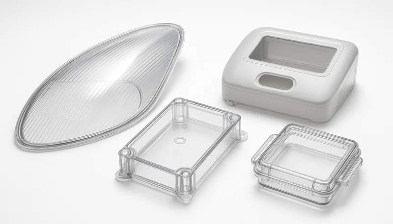
The tradeoff is worth it. PC delivers properties few other materials match—impact strength around 850 J/m notched Izod, light transmission up to 90%, and good resistance to chemicals and flame. That combination makes it the go-to material for automotive headlight lenses, medical device housings, electronic enclosures, and safety glazing.
How Do You Dry PC Before Molding?
Dry PC at 120-150°C for 3-4 hours using desiccant drying equipment before molding. PC absorbs moisture from air and hydrolyzes if processed wet, losing molecular weight and mechanical properties. The moisture content must be below 0.02% before feeding material into the hopper.
乾燥を省略するとどうなるか:水が加工温度でPC鎖と反応し、ポリマー結合を切断します。結果は分子量減少、衝撃強度損失、および銀色筋状痕やスプレーなどの表面欠陥です。この失敗モードを頻繁に見ます—新しいチームがPCを機械に急投入し、衝撃強度ゼロの曇った部品を得て、材料グレードを責めます。
Our standard drying protocol uses desiccant dryers at -40°C dew point. For standard PC grades, 120-130°C for 3 hours works. For high-heat or glass-filled PC, bump to 140-150°C for 4 hours. The key is maintaining temperature throughout the hopper, not just at the dryer outlet. Ambient moisture reabsorbs quickly—leaving dried pellets exposed for even 30 minutes can push moisture back up.
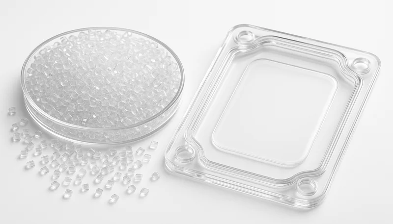
実用的なアドバイス:生産開始前に乾燥を確認するために水分分析器または簡易水分含量計を使用してください。乾燥機設定値だけに依存しないでください。乾燥機が故障したり熱電対がずれることがあり、130°Cを示しながら実際の材料温度は90°Cである場合があります。そのギャップは不良バッチと生産時間の損失を招きます。
For high-volume production, consider hopper dryers with closed-loop moisture sensors. These add cost but prevent the single most common PC failure mode. In 20 years of molding PC, we estimate 70% of first-shot failures trace back to inadequate drying. Fix drying upfront, and half your PC problems disappear.
「PCは成形前に120-150°Cで3-4時間乾燥が必要です。」真
Polycarbonate absorbs moisture from ambient air and must be dried below 0.02% moisture content using desiccant dryers to prevent hydrolysis during melt processing.
「PCペレットは環境オーブンで一夜乾燥できます。」偽
Ambient ovens lack controlled dew point and can actually increase moisture content. Desiccant drying at -40°C dew point is required to remove moisture from PC effectively.
What Are Optimal PC Molding Temperatures?
Set melt temperature to 280-310°C and mold temperature to 80-120°C for most PC injection molding applications. The exact melt temperature depends on flow length, part thickness, and PC grade. Mold temperature affects crystallinity and stress levels—higher temperatures reduce residual stress and improve optical clarity.
Starting point: 290-300°C melt, 90-100°C mold for most general-purpose PC parts. If you see incomplete fills or flow marks, increase melt temperature in 5-10°C increments up to 310°C maximum. If you see degradation, discoloration, or gas marks, reduce melt temperature. The window is narrower than for ABS or PP—too cold gives short shots, too hot degrades material rapidly.
Mold temperature is often overlooked but critical for PC. Cold molds (below 60°C) cause high residual stress, warpage, and poor surface finish. Hot molds (above 120°C) extend cycle time and can cause sticking. We run most PC tooling at 90-110°C using circulating oil or cartridge heaters. For optical parts demanding clarity, push mold temperature to 110-120°C.
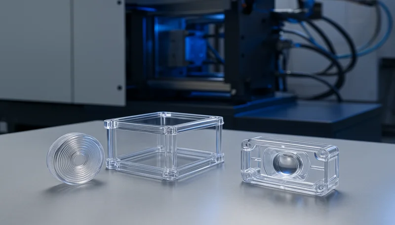
温度の段階的上げも重要です。材料を20°Cから300°Cへ瞬間的に急上昇させないでください。バレルゾーン全体で段階的なプロファイルを使用して均一な溶融を確保します。典型的なゾーン設定:後部260°C、中部280°C、前部295°C、ノズル300°C。これにより、PCは金型に入る前に融体均質性を安定させる時間を得ます。
モニタリングは必須です。融体温度センサーと定期的な粘度チェックを使用して、実際の融体温度が機械設定と一致していることを確認します。バレル熱電対が数ヶ月の生産で10-15°Cずれることがあり、チームが診断に苦労する漸進的な品質問題を引き起こします。定期的に校正し、可能であれば高温計で確認してください。
Material grade variations require temperature adjustments too. Flame-retardant PC often needs higher melt temperatures due to flame retardant additives that can reduce flow. UV-stabilized PC may process slightly differently than standard grades. Always consult the material datasheet for recommended temperature ranges from the resin manufacturer, and adjust based on your specific tooling and part geometry.
「PC融体温度は通常280-310°Cの範囲です。」真
Polycarbonate requires higher melt temperatures than many other thermoplastics due to its high glass transition temperature of approximately 147°C and high melt viscosity.
「低温金型(60°C以下)はPCのサイクル時間を改善します。」偽
Cold molds increase residual stress and warpage in PC parts, often causing dimensional instability and poor mechanical properties despite shorter cooling times.
How Do You Design Injection Molds for PC?
適切な 射出成形金型設計3 for PC requires uniform wall thickness between 1.5-4.0 mm, smooth transitions with 3:1 thickness ratio, adequate draft angles of 1-2°, and generous radii of 0.5-1.0 mm to minimize stress concentrations. Mold surface finish affects optical clarity—mirror polish yields transparent parts, while textured surfaces scatter light for diffuse appearance.
Wall thickness uniformity is non-negotiable for PC. Abrupt thickness changes cause differential cooling, leading to warpage, sink marks, and internal stress. If your design requires varying thickness, transition gradually over a distance at least three times the thickness difference. For a jump from 2mm to 4mm, maintain a ramp of at least 6mm transition length.
Gate design deserves attention. PC has high viscosity, so gate size matters more than for lower-viscosity resins. Use edge gates of 1.0-1.5mm thickness for parts up to 3mm wall thickness. Submarine or tunnel gates of 0.8-1.2mm diameter work for smaller parts. Hot runners are excellent for PC—they reduce material waste and provide better temperature control, but require higher upfront investment.
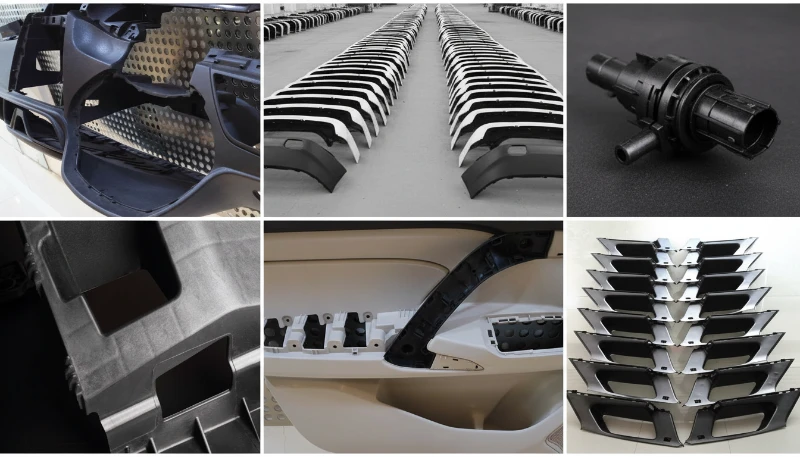
Ventilation is critical. PC produces more gas than some other resins, especially if slightly overdried or if processing near the upper temperature limit. Provide adequate venting in the mold—0.02-0.04mm vent depth, spaced every 50-80mm along the parting line. Poor venting causes burn marks, gas traps, and incomplete fills even with correct injection parameters.
Ejector design requires care. PC parts can be stubborn and mar easily. Use ejector pins of at least 5mm diameter with smooth, rounded ends. Add stripper plates or air ejection for large, flat parts. Polish ejector pins and ensure no sharp edges contact visible surfaces—PC will show every imperfection. Consider using parting line venting integrated into ejection design to improve gas escape during fill.
冷却チャネルの設計は、反りとサイクルタイムに大きく影響します。均一な冷却は内部応力を低減し、反りを防止します。可能な限り部品の輪郭に沿って冷却チャネルを設計してください。コンフォーマル冷却が理想的ですが、コストがかかります。コンフォーマル冷却が実現できない場合は、冷却チャネルを均等に配置し、熱負荷に応じて適切なサイズにしてください。水温を±2°C以内で制御することで、寸法安定性を維持できます。
What Are Common PC Molding Defects?
Common PC injection molding defects include silver streaks and splay from moisture, stress whitening and cracking from residual stress, warpage from non-uniform cooling, discoloration from thermal degradation, and sink marks from poor packing. Each defect has a specific root cause and requires targeted corrective action.
Silver streaks or splay appear as wavy silver lines on the part surface. This almost always indicates moisture in the material. Even if you dried for 3 hours, verify moisture content is below 0.02%. Check dryer function, ensure hopper lids are closed, and prevent material from sitting exposed to ambient air. We see this constantly—dryers set correctly but operators leave the hopper lid open for hours.
Stress whitening appears as milky patches when parts are bent or impacted. This indicates high residual stress from cooling too quickly or from improper ejection. Increase mold temperature by 10-20°C to reduce stress. Check for undercuts or sharp features causing high ejection forces. Ensure adequate packing but avoid overpacking, which locks stress into the part.
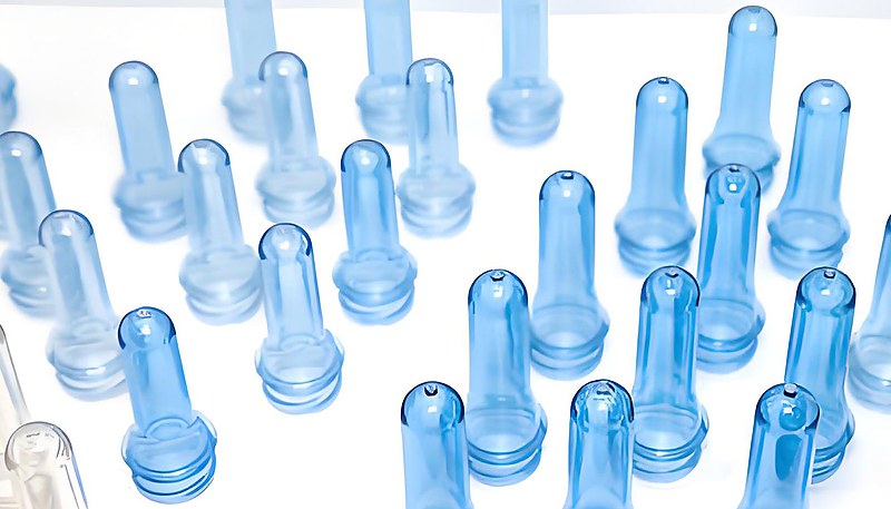
Warpage and dimensional instability trace back to non-uniform cooling or wall thickness variation. Check cooling channel layout—ensure uniform cooling across the part. If wall thickness varies unavoidably, adjust packing and cooling times to compensate. Sometimes adjusting gate location or adding flow leaders helps balance cooling rates across the part. Increasing mold temperature can also reduce residual stress and improve dimensional stability.
変色(黄変または褐変)は熱分解を示しています。融体温度を5-10°C下げます。バレル滞留時間を確認してください—サイクル間で溶融材料を長時間保持していないことを確認します。バレルまたはスクリュー内で材料が停滞するデッドスポットを探します。再生材を使用する場合は、最大25-30TP3Tまでに制限し、十分に乾燥されていることを確認します。また、異物や他の樹脂からのクロスコンタミネーションによる汚染も確認してください。これらは色変化を引き起こす可能性があります。
Flow marks and weld lines also plague PC parts, especially with long flow lengths or complex geometries. Flow marks appear as visible lines where material fronts meet. Weld lines occur where material flows around an obstacle and rejoins. These can be weak points structurally. Optimize gate location to minimize flow length, consider multiple gates for large parts, and increase melt temperature to improve flow merging. Surface finish helps hide minor flow marks—textured surfaces conceal these defects better than glossy finishes.
「PC部品の銀色筋状痕は通常、乾燥不足を示しています。」真
Moisture in PC vaporizes at melt temperatures, creating gas bubbles that appear as silver streaks on the part surface. Proper desiccant drying eliminates this defect.
「高い金型温度は常にサイクル時間を短縮します。」偽
While higher mold temperature reduces residual stress and improves part quality, it increases cooling time and extends cycle time. The optimal mold temperature balances quality and efficiency.
How Do You Optimize PC Processing Parameters?
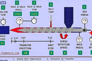
Optimize PC processing by setting injection speed to medium-fast for filling, using a packing pressure of 50-80% of injection pressure for 2-4 seconds, maintaining cooling time based on wall thickness at approximately 10-12 seconds per mm, and back pressure of 50-150 bar to improve melt homogeneity. Screw speed of 50-100 RPM provides adequate mixing without excessive shear heating.
Injection speed affects part quality significantly. Too slow causes material to freeze prematurely, resulting in short shots or weld lines. Too fast causes jetting, high shear heating, and potential degradation. Start at medium speed and adjust based on part appearance. For thin-walled parts needing long flow, push speed higher. For thick parts where flash is a concern, reduce speed.
Packing pressure compensates for shrinkage as the material cools. PC has relatively low shrinkage (0.5-0.7%), but packing still matters for dimensional accuracy. Start packing at 60% of injection pressure for 3 seconds, then adjust. Too little packing causes sink marks and dimensional undershoot. Too much packing creates flash, high residual stress, and can even cause ejection problems.
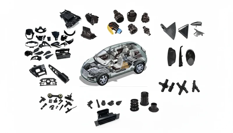
Cooling time depends primarily on wall thickness but also on mold temperature. A rough guideline: 10-12 seconds per mm of wall thickness for PC. A 3mm wall needs roughly 30-36 seconds cooling time. Increase this for thicker sections or parts requiring high dimensional precision. Use infrared temperature probes or thermal imaging to verify the part is solidifying evenly.
Screw recovery and back pressure affect melt quality. Use back pressure of 50-150 bar to improve melt homogeneity and reduce air entrapment. Keep screw speed moderate—50-100 RPM—to avoid excessive shear heating that can degrade PC. Ensure shot size is 20-30% of barrel capacity to maintain consistent melt temperature between shots.
「PCの収縮率は通常0.5~0.7%です。」真
Polycarbonate exhibits relatively low shrinkage compared to semi-crystalline materials, but packing and cooling parameters still critically affect final dimensions and stability.
「高い背圧は常に部品品質を向上させます。」偽
While back pressure improves melt homogeneity, excessive back pressure can cause material degradation, increase barrel temperature, and create color shifts. Optimize back pressure rather than maximizing it.
What Are Typical PC Injection Molding Applications?
PC injection molding serves automotive headlight lenses and light covers, electronic enclosures and connectors, medical device housings and components, safety glazing and riot shields, optical discs and lenses, and consumer electronics requiring impact resistance and clarity. The combination of optical properties, toughness, and heat resistance makes PC versatile across industries.
Automotive applications dominate PC usage. Headlight lenses, fog light covers, and taillight assemblies require transparency and impact resistance. PC withstands UV exposure (with appropriate stabilizers) and maintains clarity at elevated temperatures under the hood. We mold automotive light components with tight optical specifications—transmission above 88% and yellowness index below 2.0.
電子機器および電気用途では、筐体、コネクタ、および難燃性が必要な部品にPCを使用します。難燃性PCグレードはUL94 V-0標準を満たしながら機械特性を維持します。これらの部品は電子部品からの熱にも耐え、電気絶縁を提供する必要もあります。PCの絶縁耐力15-20 kV/mmは多くの電気用途に適合します。
医療機器は成長しているPC市場です。手術器具のハウジング、流体処理部品、および医療機器筐体は、PCの強靭性、透明性、および滅菌対応性の恩恵を受けます。医療グレードPCは生体適合性と厳格な加工管理が必要であり、クロスコンタミネーションを防ぐために専用設備が必要となることが多いです。上海施設は、医療機器製造のためのISO 13485認証で運営されています。
よくある質問
How long does PC need to be dried before injection molding?
PC requires 3-4 hours of drying at 120-150°C using desiccant equipment before molding. The moisture content must reach below 0.02% to prevent hydrolysis during melt processing. Higher drying temperatures (140-150°C) are needed for glass-filled or high-heat PC grades. Never rely on ambient drying or skip drying steps—this is the single most common cause of PC part failure. Use a desiccant dryer with -40°C dew point and verify moisture content with a moisture analyzer before production starts. Even dried PC reabsorbs moisture quickly when exposed to air, so keep hopper lids closed and material sealed.
What is the ideal melt temperature for PC injection molding?
The ideal melt temperature for PC ranges from 280-310°C depending on the grade and part geometry. General-purpose PC typically processes at 290-300°C. Flame-retardant or glass-filled grades may require slightly higher temperatures up to 310°C. Exceeding 310°C risks thermal degradation and discoloration. Start at 290°C and adjust in 5-10°C increments based on part fill appearance and surface quality. Use a gradual temperature profile across the barrel zones to ensure uniform melting without thermal shock. Monitor for signs of degradation like yellowing or gas marks.
What mold temperature is best for PC parts?
Optimal mold temperature for PC is 80-120°C, with 90-110°C being the typical range for most applications. Higher mold temperatures (110-120°C) reduce residual stress and improve optical clarity for transparent parts. Lower mold temperatures (80-90°C) provide faster cycle times but may increase warpage risk. Adjust based on part requirements—optical parts need hotter molds than opaque components. Circulating oil or cartridge heaters provide uniform temperature control for PC tooling. Cold molds below 60°C cause high residual stress and poor surface finish results.
Why do PC parts have silver streaks on the surface?
Silver streaks or splay on PC parts indicate moisture in the material, typically from insufficient drying. Even dried PC can reabsorb moisture if left exposed to ambient air. Ensure desiccant drying at 120-150°C for 3-4 hours with a -40°C dew point dryer. Verify moisture content is below 0.02% before molding. Check dryer function and keep hopper lids closed to prevent moisture reabsorption. Silver streaks are the most visible sign of moisture-related hydrolysis during melt processing. This is the most common PC failure and requires immediate drying verification.
What causes warpage in PC injection molded parts?
PCの反りは、不均一冷却、壁厚差、または高い残留応力が主な原因です。均一な壁厚と滑らかな遷移(3:1比率)および十分な冷却チャンネルを確保します。金型温度を10-20°C上げて残留応力を減らします。最も厚い部分に対して冷却時間が十分であることを確認します。ゲート位置の調整やフローリーダーの追加により、部品全体の冷却速度を平衡化することが役立つ場合もあります。成形時に残留応力が管理されていない場合、反りは時間とともに悪化することが多いです。ツーリング前に、潜在的な反り領域を識別するために金型流動解析を使用してください。
Can PC injection molding produce transparent parts?
Yes, PC injection molding can produce transparent parts with light transmission up to 90%. Transparency requires high mold temperatures (110-120°C), proper drying to prevent splay, and highly polished mold surfaces. The mold surface finish directly transfers to the part—mirror-polished cavities yield clear parts, while textured surfaces create diffuse or translucent appearance. Avoid scratches or imperfections in the mold that will affect optical quality. Use PC grades specifically formulated for optical applications rather than general-purpose resin. Monitor yellowness index to ensure consistent clarity.
What is the shrinkage rate of PC in injection molding?
PC has a typical shrinkage rate of 0.5-0.7%, which is relatively low compared to semi-crystalline materials. The low shrinkage helps dimensional accuracy but does not eliminate the need for proper processing. Packing pressure, cooling time, and mold temperature all affect final dimensions. Use standard shrinkage values for initial mold design but validate actual shrinkage during T1 sampling with the specific PC grade. Different PC grades may have slightly different shrinkage characteristics. Measure shrinkage in flow and transverse directions as they can vary.
Quick rule: Dry PC at 120-150°C for 3-4 hours, run melt at 290-300°C, keep mold at 90-110°C, and maintain uniform wall thickness. If you see silver streaks, check drying. If parts warp, balance cooling. If dimensions drift, adjust packing. Master these basics, and PC becomes a reliable workhorse rather than a problematic material.
上海工場では45台の射出成形機と2005年からの20年以上の経験があり、自動車、電子機器、および医療用途で毎日PCを加工しています。8人のシニアエンジニアと30人以上の英語対応プロジェクトマネージャーは、材料の要件を理解し、PC部品のツーリングとプロセスを最適化するのに役立ちます。
We build 100+ molds per month in our in-house tooling facility, supporting projects from rapid prototyping through full-scale production. Our 400+ material capability includes multiple PC grades, and we maintain ISO 9001 and 13485 certification for quality management and medical device manufacturing.
Ready to mold PC parts with confidence? Get a free quote and technical consultation for your project.
-
polycarbonate: Polycarbonate is an amorphous engineering thermoplastic with outstanding impact strength and optical clarity, typically used for parts requiring high toughness and transparency. ↩
-
injection molding process: Injection molding process is a manufacturing method where molten plastic is injected into a mold cavity under high pressure, cooled, and ejected as a solid part. ↩
-
injection mold design: Injection mold design refers to the engineering process of creating the tooling components and features that determine how plastic parts are formed during the molding cycle. ↩



 EN
EN  ES
ES  FR
FR  DE
DE  PT
PT  AR
AR  RU
RU  JA
JA  KO
KO  IT
IT  NL
NL  TR
TR  PL
PL 