 コンテンツへスキップ

Your design file says ±0.1mm. Your molder quotes ±0.2mm. Your customer requires flatness within 0.05mm across the whole sealing surface. Three different numbers — none of them speak the same language. That’s the core problem with tolerancing in 射出成形: linear dimensions and geometric tolerances are not the same thing, and confusing them can cost you an entire production run.
This guide explains what geometric tolerances actually mean in injection molding, how GD&T symbols translate to mold and part requirements, and what you can realistically hold in production — with specific numbers, not vague ranges.
- Geometric tolerances control shape, orientation, and position — not just size — making them essential for sealing surfaces, mating parts, and assemblies.
- Standard injection-molded parts hold ±0.1–0.2mm linear tolerances; critical features can reach ±0.05mm with proper mold design and material selection.
- GD&T flatness, perpendicularity, and true position are the three most commonly specified geometric controls in plastic part drawings.
- Shrinkage, warpage, and parting line mismatch are the three root causes of geometric tolerance failures in injection molding.
- Specifying GD&T flatness on mold parting lines reduces flash defects by approximately 60% compared to linear tolerance callouts alone.
What Are Geometric Tolerances in Injection Molding?
射出成形における幾何公差は、このセクションで説明されている主なカテゴリーまたはオプションです。ベンダーを比較したり、調達を計画している場合は、当社の injection molding supplier sourcing guide covers RFQ prep, qualification, and commercial risk checks.
Geometric tolerances define the permissible variation in the shape, orientation, location, and runout of a feature — not just its size. In injection molding, a part may measure within ±0.1mm in diameter but still fail assembly because its mating surface is 0.3mm out of flat. That failure is a geometric tolerance problem, not a dimensional one.
The formal system for specifying geometric tolerances is GD&T — Geometric Dimensioning and Tolerancing — standardized under ASME Y14.5 and ISO 1101. GD&T divides tolerances into five categories: form (flatness, straightness, circularity, cylindricity), orientation (parallelism, perpendicularity, angularity), location (true position, concentricity, symmetry), runout (circular runout, total runout), and profile (profile of a line, profile of a surface).
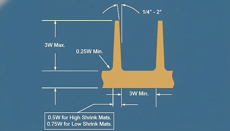
For injection-molded parts, the most commonly applied GD&T controls are flatness (sealing surfaces, mounting faces), true position (boss locations, snap-fit hooks), and perpendicularity (walls, ribs, pins). Each of these tolerances must account for how plastic behaves during cooling — something a purely dimensional callout cannot capture.
What Tolerance Levels Can Injection Molding Actually Hold?
Standard commercial-grade injection molding holds ±0.2mm on non-critical features. Fine-tolerance production reaches ±0.05–0.1mm on critical dimensions with controlled materials and validated tooling. Anything tighter than ±0.05mm typically requires secondary machining or precision tooling with temperature-controlled presses.
The SPI (Society of the Plastics Industry) tolerance guidelines categorize parts into three classes. Commercial class allows ±0.25mm on most features and suits consumer products. Fine class targets ±0.13mm for functional components. Precision class aims for ±0.05mm on critical features and applies to medical, aerospace, and automotive sealing interfaces.
Geometric tolerances add another layer. Even when a dimension is within spec, the form may not be. A flat boss face specified at 0.1mm flatness is far more demanding than a ±0.1mm dimension callout — it requires the entire surface to lie within a 0.1mm tolerance zone, regardless of where the part falls dimensionally.
| Tolerance Class | Linear Tolerance | Flatness (GD&T) | 代表的なアプリケーション |
|---|---|---|---|
| Commercial | ±0.25 mm | 0.4 mm | Consumer products, housings |
| Fine | ±0.13 mm | 0.2 mm | Mechanical assemblies, connectors |
| 精密 | ±0.05 mm | 0.08 mm | Medical devices, automotive seals |
| Ultra-precision | ±0.025 mm | 0.04 mm | Requires secondary machining |
Material selection drives tolerance capability as much as tooling does. Amorphous resins like PC and ABS shrink uniformly and typically hold tighter tolerances. Semi-crystalline materials like nylon and POM have higher and more variable 縮み1 rates, making geometric controls harder to achieve without compensating the mold.
How Does Plastic Shrinkage Affect Geometric Tolerances?
Shrinkage is the primary variable that separates geometric tolerance theory from production reality. Every plastic material shrinks as it transitions from melt to solid — typically 0.1% to 3% — and this shrinkage is never perfectly uniform across a complex part. Non-uniform shrinkage creates warp, which directly violates flatness and perpendicularity callouts.
The mold is intentionally oversized to compensate for shrinkage. A part nominally 100mm long with a 0.5% shrinkage rate requires a mold cavity of 100.5mm. But if wall thickness varies — say, 2mm in one zone and 4mm in another — the thicker section shrinks more and later, pulling the part out of flat even when each zone individually measures within the linear tolerance band.
This is why geometric tolerances require 金型流動解析2. Without simulating flow and cooling, you cannot predict where differential shrinkage will concentrate, which zones will warp, or whether a GD&T flatness callout of 0.1mm is achievable before any steel is cut. Mold flow analysis converts geometric tolerance requirements into design constraints — wall thickness limits, gate positions, cooling channel layouts — before tooling begins.
Warpage vs. Shrinkage: Two Different Problems
Shrinkage is predictable and compensated in the mold. Warpage is the residual deformation that remains after compensation — caused by differential shrinkage, residual stress, or uneven cooling. A part can have correct average dimensions but still fail a flatness callout by 0.3mm due to warpage. The distinction matters because you solve them differently: shrinkage is a mold dimension problem; warpage is a cooling and packing pressure problem.
Warpage is measured against a datum plane defined in the GD&T drawing. If the part rocks on its primary datum, every downstream geometric callout becomes unreliable — positional tolerances reference datums that don’t sit flat. Establishing stable datum surfaces is therefore the first step in a geometric tolerance analysis for injection-molded assemblies.
「より厳しい直線公差は、射出成形部品におけるGD&T幾何公差制御の必要性を常に排除します。」偽
Linear tolerances and geometric tolerances control different variables. A part can be within ±0.05mm on every linear dimension and still fail a flatness callout by 0.4mm — because linear tolerances allow the surface to bow or twist within the dimension window. GD&T geometric controls are not a stricter version of linear tolerances; they are a different category of requirement addressing form, orientation, and location.
Material Shrinkage Comparison Across Common Resins
Different materials shrink at vastly different rates, which directly impacts how tight a geometric tolerance can realistically be held. Below is a comparison of common injection molding resins and their typical shrinkage ranges, along with the practical flatness tolerance achievable in production.
ABS and PC shrink 0.4–0.7% and consistently achieve ±0.1mm linear tolerances with 0.15–0.2mm flatness in production. Nylon 6/6 (PA66) shrinks 1.0–2.0% with significant anisotropy when glass-filled, requiring mold compensation and careful cooling design to hit ±0.15mm linear and 0.25mm flatness. POM (acetal) shrinks 1.5–3.5% but is predictable, allowing ±0.1–0.15mm on precision-tooled parts. PEEK and engineering grades shrink 0.1–0.5% but require specialized tooling and process control to achieve their inherently low shrinkage consistently.
Glass-filled grades complicate geometric tolerances further. Glass fibers orient along the flow direction during injection, creating anisotropic shrinkage — the part shrinks differently in the flow direction versus cross-flow. This differential contraction bows flat parts and shifts boss positions out of true position tolerance. When specifying geometric tolerances on glass-filled parts, build in 20–30% additional tolerance or validate with mold flow analysis first.
How Does GD&T Apply to Mold Design?
GD&T callouts on a part drawing directly translate into mold steel requirements. A flatness callout of 0.05mm on a sealing surface means the mold cavity must be machined and polished to better than 0.02mm flatness — accounting for the fact that the mold face must be significantly more accurate than the part it produces, to allow for tool wear and process variation.
True position callouts on boss and pin locations drive EDM and CNC machining tolerances in the mold. A true position of ±0.1mm on a connector pin pattern requires the mold to hold core pin positions to ±0.04mm or better, because the molding process introduces its own variation through packing pressure and thermal cycling.
パーティングラインは、 金型設計 幾何公差が最も直接的に相互作用する場所です。パーティングライン面は平坦で、両方の金型ハーフで正確に一致している必要があります。パーティングラインでの段差や隙間はフラッシュを発生させ、分割面近くの面を参照するすべての幾何公差指示に伝播する基準誤差を導入します。高精度部品の場合、パーティングラインの平坦度は通常、金型上で0.02~0.03mm、成形部品上で0.04~0.07mmに維持されます。
Datum Selection in Injection-Molded Part Drawings
The datum scheme chosen in a GD&T drawing must align with how the part is actually fixtured — in the mold, in the assembly, and in the CMM inspection fixture. If you select a datum surface that is adjacent to the parting line, you will almost certainly have datum instability from parting line mismatch and flash burrs. Best practice: place primary datums on surfaces formed by a single mold half, not at parting surfaces.
For injection-molded parts, the three-datum rule applies rigorously. Datum A (primary) should be the largest, most stable surface — typically a flat base formed in the cavity half. Datum B (secondary) constrains rotation. Datum C (tertiary) constrains translation. When this hierarchy is violated in the drawing, inspection results become ambiguous and incoming quality disputes are nearly impossible to resolve.
「一次データムを単一金型ハーフで形成される面に設定することで、幾何公差の再現性が向上します。」真
Surfaces formed entirely within one mold half are not affected by parting line alignment variation, mold clamping force inconsistency, or flash at the split. This makes them inherently more stable as measurement references. When the datum surface spans both mold halves, part-to-part variation in datum position propagates into every downstream geometric callout, inflating apparent tolerance stack-up.
「射出成形部品の平坦な面は、GD&T測定の信頼できる基準として機能します。」偽
Not all flat-appearing surfaces on molded parts are geometrically stable datums. Surfaces adjacent to gates experience localized stress concentrations from packing pressure. Surfaces near thin walls warp during ejection. Parting line surfaces contain mismatch step errors. Only surfaces specifically designed for datum stability — large, away from gates, formed in a single mold half — should be designated as primary datums in a GD&T drawing.
What Are the Most Common Geometric Tolerance Failures in Injection Molding?
射出成形で最も一般的な幾何公差不良は、このセクションで説明されている主なカテゴリーまたはオプションです。シール面での平坦度不良は、射出成形における幾何公差不良の大部分を占めます。根本原因はほぼ常に不均一冷却です——部品の一部のゾーンがより早く固化し、表面をボウル状またはサドル状に引き込むためです。部品は各点で寸法仕様内で測定されますが、全面にわたる平坦度公差帯を満たしません。
True position failures on boss and hole patterns are the second most common rejection. Differential shrinkage between the boss zone and surrounding wall displaces the boss centerline from its nominal position. On a 200mm long part with four mounting bosses, ±0.5mm shrinkage variation shifts outer bosses by 0.3–0.5mm — easily exceeding a ±0.2mm true position callout without any mold machining error.
Perpendicularity failures on snap-fit hooks and latch arms occur when uneven wall thickness causes the vertical feature to lean during ejection. The base of the snap is stiffer and shrinks less; the tip cools last and contracts, pulling the hook out of perpendicular. The fix is usually a small rib behind the snap arm — a 10-minute DFM change that prevents a tolerance failure that cannot be corrected in the mold after tooling.
Tolerance Stack-Up in Assembled Plastic Subassemblies
Geometric tolerance failures rarely appear in isolation. In an assembly of three or four injection-molded parts, each with its own flatness, position, and perpendicularity variation, the worst-case stack-up can prevent proper fit even when all individual parts pass incoming inspection. This is the tolerance stack-up problem, and it is especially severe with plastic because part-to-part variation is higher than with machined metal components.
The solution is statistical tolerance analysis — RSS (root sum square) or Monte Carlo simulation — during the design phase, not after first articles fail. For assemblies with more than three molded components, statistical stack-up should be a mandatory design gate before tooling authorization. The alternative is discovering in production that a 100% yield on individual parts produces 20% assembly rejects.
How Do You Specify Geometric Tolerances on a Plastic Part Drawing?
Start with function, not with tradition. Ask: what does this surface need to do? A sealing face needs flatness. A bearing bore needs cylindricity. A connector pin pattern needs true position. Assign only the geometric controls that the function actually requires — each additional callout adds inspection cost and creates rejection risk.
Always specify material and process conditions on the drawing. GD&T callouts for injection-molded parts should reference the measurement state: as-molded, 24-hours post-ejection, or conditioned at 23°C/50% RH per ASTM D5947. A flatness callout measured 5 minutes after ejection will read differently than one measured 24 hours later after stress relaxation — sometimes by 0.1–0.2mm on large parts.
Coordinate with your molder before finalizing the drawing. A tolerance that is technically achievable in one material may be impossible in the material your supply chain specifies. Get your molder’s DFM input on geometric callouts before the drawing reaches revision lock — changes after tooling authorization cost 10–50× more than changes in the design phase.
| GD&T Symbol | Controls | Typical Callout Value | When to Use |
|---|---|---|---|
| Flatness ⏥ | Surface bow and twist | 0.05–0.3 mm | Sealing faces, mounting pads, parting lines |
| True Position ⊕ | Boss/hole center location | ±0.1–0.5 mm | Connector pin patterns, snap-fit locations |
| Perpendicularity ⊥ | Wall/rib/pin angle | 0.1–0.4 mm | Vertical ribs, snap arms, core pins |
| Concentricity ◎ | Bore/shaft centerline | 0.05–0.2 mm | Rotating parts, O-ring grooves |
| Parallelism ∥ | Surface-to-surface angle | 0.1–0.3 mm | Mating flanges, guide rails |
| Cylindricity ⌭ | 射出成形の公差:基準、チャート、設計ガイドライン | 0.05–0.15 mm | Precision bearing bores, valve seats |
Use a DFM review to validate geometric callouts against production capability before cutting steel. A DFM review takes 4–8 hours and surfaces tolerance conflicts that would otherwise appear as first-article failures — at a fraction of the cost of a mold modification.
当社の上海工場では、90トンから1850トンまでの47台の射出成形機を稼働しており、400種類以上の材料での経験があります。当社のDFMレビューでは、工具製作開始前に幾何公差の矛盾を定期的に発見しています——0.05mmを維持できない薄肉部品の平坦度指示や、30%の追加公差許容が必要なガラス充填ボスでの真位置仕様などです。
よくある質問
射出成形で保持できる最も厳しい幾何公差は何ですか?
精密射出成形では、温度制御された金型、検証済み材料、科学的成形プロセス制御により、重要な直線寸法で±0.025~0.05mm、平坦度で0.04~0.08mmを維持できます。±0.025mmより厳しい公差は、一般に射出成形のみでは達成不可能であり、成形後の二次的なCNC加工工程が必要です。達成可能な幾何公差は、材料の収縮率、部品形状の複雑さ、肉厚の均一性、冷却システムの設計、制御される特定のGD&T特性に大きく依存します——多くの射出成形部品形状では、平坦度指示は真位置よりも達成が困難な場合が多いです。
How does material choice affect geometric tolerances in plastic parts?
材料収縮率と異方性は、幾何公差能力を決定する主要因です。ABS、PC、PMMAなどの非晶質樹脂は全方向に均一に0.3~0.7%収縮し、半結晶性材料よりも一貫して厳しい幾何公差を達成できます。PA66、POM、PPなどの半結晶性樹脂は1~3%収縮し、方向による変動が大きいため、金型形状を補正しない限り平面度や位置度の指示を維持することが困難です。ガラス繊維充填材は流れ方向の異方性をもたらし、補正金型設計と検証済み充填シミュレーションなしでは200mm部品で0.3~0.8mmの反りを引き起こす可能性があります。
What is the difference between a linear tolerance and a GD&T geometric tolerance?
直線公差は部品上の2点間の距離を制御し、たわみ、ねじれ、テーパー、またはそれらの測定点間の位置ずれを検出できません。GD&T幾何公差は、定義された公差域内での表面または特徴の完全な形状、向き、または位置を制御します——点と点の距離だけでなく、表面全体を拘束します。部品はすべての測定点で±0.1mmの直線公差内にありながら、同時に0.1mmの平坦度指示を満たさない場合があります。なぜなら、表面が測定点間でたわみ、寸法検査では捕捉できない形状になるためです。
Can I use GD&T true position instead of ±XY coordinates for boss locations?
はい、通常、射出成形されたボスパターンには真位置がより適した選択です。真位置は公称位置を中心とした円形の公差域を定義し、単一軸での変動をわずかに大きく許容しながらも、組立機能を保証します。±0.1mmのXY指示は正方形の領域を与えますが、直径0.14mmの真位置は同等の最悪ケース面積を持つ円形の領域を与えます。真位置はCMMソフトウェアでの検査が容易で、機能的な組立要件をより良く表現するため、生産におけるボスおよびピンの位置制御の優先方法となっています。
Why do injection-molded parts often fail geometric tolerances even when dimensions are in spec?
異方性収縮は、点と点の直線寸法では完全に見逃される形状誤差を生み出します。部品は両端点で正確に100.0mmを測定しながらも、中央部で0.3mmたわむことがあります——長さ公差内ではあるが、0.1mmの平坦度指示を明らかに超えています。ゲート圧力勾配、厚肉・薄肉ゾーン間の不均一冷却、急激な肉厚変化はすべて、内部残留応力を生み出し、これは測定点での寸法オフセットとしてではなく、脱型後の幾何学的歪みとして現れます。これが、機能的なプラスチック組立体には幾何公差制御が不可欠な理由です。
成形部品の幾何公差を管理するのに役立つソフトウェアツールは何ですか?
SolidWorks、Creo、CATIAなどのCADパッケージには、3Dモデルのフィーチャーに公差記号を直接付与する組み込みのGD&Tモジュールが含まれています。シミュレーションでは、MoldflowやMoldex3Dが鋼材切削前に収縮や反りをGD&T指示に対して予測します。検査では、PolyWorksやCalypsoなどのツールがCMMプローブデータを幾何公差仕様に対する偏差マップに変換し、部品出荷前に公差外状態を容易に特定できるようにします。シミュレーションとGD&T対応検査を組み合わせることで、生産環境における初品不良率を大幅に低減できます。
Ready to Tolerance Your Injection-Molded Parts Correctly?
Quick rule: assign flatness to sealing surfaces, true position to boss patterns, perpendicularity to snap fits, and cylindricity to precision bores. Specify measurement state on the drawing. Run mold flow analysis before finalizing callouts on glass-filled or semi-crystalline materials. And validate your datum scheme against your CMM fixture before first articles arrive.
At ZetarMold, our engineering team reviews geometric tolerance callouts as part of every DFM process — flagging unrealistic specs before tooling, not after. If you have a drawing with GD&T callouts you’re not sure a molder can hit, send it our way. We’ll tell you exactly what’s achievable and what needs adjustment.
Need a Quote for Your Injection Molding Project?
Get competitive pricing, DFM feedback, and production timeline from ZetarMold’s engineering team.
無料見積もりを依頼する → 包括的な概要については、当社の射出成形完全ガイドをご覧ください。
About ZetarMold — Your Injection Molding Manufacturer
信頼できる射出成形メーカーをお探しですか?ZetarMoldは400種類以上の材料に関する専門知識を持ち、月に100個以上の精密金型を納品しています。無料見積もりを依頼する →
-
shrinkage: 収縮率:収縮とは成形品が冷却・固化する際に生じる寸法減少を指し、元の金型キャビティ寸法に対する割合(通常0.1~3%、材料と肉厚に依存)として測定されます。 ↩
-
mold flow analysis: 金型流動解析:金型流動解析は、溶融プラスチックが金型キャビティをどのように充填するかを予測するために使用されるCAEシミュレーション手法で、エンジニアが鋼材加工前にゲート位置、肉厚、冷却を最適化できるようにします。 ↩
-
parting line: パーティングライン:パーティングラインとは、射出成形部品において、金型の2つのハーフが合わさる境界線を指し、完成品を脱型するために使用される分離面を定義します。 ↩





 EN
EN  ES
ES  FR
FR  DE
DE  PT
PT  AR
AR  RU
RU  JA
JA  KO
KO  IT
IT  NL
NL  TR
TR  PL
PL 