 Vai al contenuto

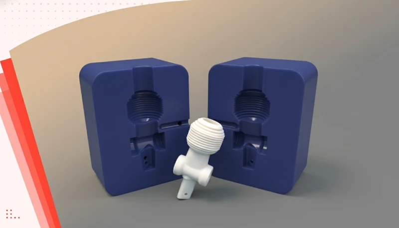
estrazione del nucleo1 in stampaggio a iniezione è un meccanismo di stampo che ritrae nuclei interni per rilasciare parti con sottosquadri, filettature interne e fori laterali che la normale direzione di apertura dello stampo non può formare. Senza di esso, i produttori avrebbero bisogno di costose operazioni secondarie — o semplicemente non potrebbero produrre molte geometrie complesse su larga scala. Nella nostra esperienza presso ZetarMold, il ritiro del nucleo è una delle tre principali caratteristiche dello stampo che separa un buon progetto di stampo da uno eccellente.
- I meccanismi di ritiro del nucleo consentono agli stampi di formare sottosquadri, fori laterali e filettature interne che la normale apertura dello stampo non può creare
- Esistono tre tipi principali: idraulico, meccanico e pneumatico — ciascuno adatto a diversi requisiti di forza e precisione
- Il ritiro del nucleo aggiunge 15-30% al costo dello stampo ma spesso elimina completamente le operazioni di lavorazione secondarie
- La corretta tempistica della sequenza di ritiro del nucleo è fondamentale per evitare difetti delle parti e danni allo stampo
- Angoli di sformo e spessori di parete adeguati attorno alle caratteristiche con estrazione del nucleo riducono significativamente i tassi di difetti
Che cos'è il core pull nello stampaggio a iniezione?
Un ritiro del nucleo è una stampo a iniezione che si ritrae prima dell'espulsione per rilasciare sottosquadri, filettature interne, fori laterali o scanalature incassate. Il nucleo viene mantenuto in posizione durante l'iniezione, quindi ritirato prima o durante l'apertura dello stampo in modo che la parte possa essere espulsa liberamente. In pratica, i ritiri del nucleo sono azionati da cilindri idraulici, perno angolare meccanico2s, o sistemi pneumatici.
La scelta dipende dalla forza richiesta, dai vincoli di tempo ciclo e dalla geometria del pezzo. Nella nostra fabbrica di Shanghai, realizziamo regolarmente stampi con fino a otto core pull indipendenti su un unico strumento per componenti automobilistici e medicali.
Nella nostra fabbrica di Shanghai, operiamo 47 macchine per stampaggio a iniezione da 90T a 1850T, dandoci la flessibilità di utilizzare stampi a ritiro del nucleo per un'ampia gamma di dimensioni e materiali delle parti.
Il meccanismo di ritiro del nucleo è distinto dal sistema di espulsione standard. Mentre gli espulsori spingono la parte fuori dallo stampo dopo l'apertura, i ritiri del nucleo ritraggono gli elementi formativi interni prima o durante l'apertura dello stampo. Questa sequenza — prima ritiro del nucleo, poi apertura dello stampo, quindi espulsione — è ciò che rende possibili le caratteristiche a sottosquadro senza danneggiare la parte.
I ritiri del nucleo sono particolarmente comuni nei connettori automobilistici, negli alloggiamenti di dispositivi medici, negli involucri di elettronica di consumo e in qualsiasi applicazione in cui clip interne, agganci a scatto o inserti filettati vengono stampati direttamente nella parte anziché aggiunti come operazioni secondarie.
Perché si utilizza il core pull nello stampaggio a iniezione?
La ragione principale è semplice: gli stampi per iniezione standard possono rilasciare solo parti che non hanno caratteristiche perpendicolari alla direzione di apertura dello stampo. Qualsiasi sottosquadro, filettatura interna o foro laterale richiede un meccanismo per ritrarre l'acciaio formativo prima che la parte possa essere espulsa. Senza il ritiro del nucleo, i produttori affrontano tre alternative negative. Primo, ridisegnare la parte per eliminare i sottosquadri — il che spesso compromette la funzionalità. Secondo, aggiungere un'operazione di lavorazione secondaria per creare la caratteristica dopo lo stampaggio — aumentando costi, tempi e potenziali variazioni qualitative. Terzo, utilizzare un inserto sciolto che un operatore posiziona e rimuove manualmente ogni ciclo — rallentando drasticamente la produzione e introducendo incoerenza. Il ritiro del nucleo risolve tutti e tre i problemi contemporaneamente.
La caratteristica viene stampata in sede con piena precisione, il tempo di ciclo rimane automatizzato e non è necessaria alcuna operazione secondaria. Per produzioni in serie di parti complesse, il ritorno sull'investimento per gli utensili a ritiro del nucleo viene generalmente realizzato entro i primi 10.000-50.000 cicli, a seconda della complessità del pezzo.
| Benefit | Senza Estrazione del Nucleo | Con Ritiro del Nucleo |
|---|---|---|
| Filettature interne | Operazione di filettatura secondaria | Stampati in posizione, costo secondario zero |
| Fori laterali | Foratura post-stampaggio | Formato durante il ciclo di iniezione |
| Sottosquadri a clip | Riprogettazione del componente o inserto mobile | Formazione e rilascio automatizzati |
| Consistenza del ciclo | Il posizionamento manuale dell'inserto varia | Automazione completa, risultati ripetibili |
| Tooling cost | Costo iniziale inferiore, costo per parte più alto | Costo iniziale più alto, costo per parte più basso |
“Core pull mechanisms allow injection molds to produce parts with features that are impossible with standard two-plate molds.”Vero
Corretto. I core pull ritraggono gli elementi di formatura interni, consentendo sottosquadri, filettature interne e fori laterali che la normale direzione di apertura dello stampo non può rilasciare.
“Core pull is only necessary for very large injection-molded parts.”Falso
Falso. L'estrazione del nucleo viene utilizzata su parti di tutte le dimensioni — dai componenti medicali micro-stampati sotto i 5 mm ai grandi pannelli automobilistici. Il fattore decisivo è la geometria della parte (sottosquadri, filettature, fori laterali), non le dimensioni della parte.
Quali tipi di meccanismi di ritiro del nucleo esistono nello stampaggio a iniezione?
Esistono tre metodi principali di azionamento dell'estrazione del nucleo nello stampaggio a iniezione: idraulico, meccanico e pneumatico. Ciascuno ha vantaggi distinti e la scelta giusta dipende dai requisiti di forza, dai vincoli di tempo di ciclo, dalle dimensioni dello stampo e dalle considerazioni di manutenzione. estrazione idraulica del nucleo3 is the most common type for medium-to-large molds and high-force applications. Hydraulic cylinders are mounted on the mold and connected to the machine’s hydraulic system. They provide high retract forces — typically 5 to 50+ tons — making them ideal for large cores, multi-cavity molds, and applications where the core must overcome significant packing pressure before retracting. The main advantages are high force capacity and precise speed control.
Gli svantaggi sono la potenziale perdita di olio (un problema negli ambienti di cleanroom), una risposta leggermente più lenta rispetto ai sistemi meccanici e la necessità di linee idrauliche che complicano l'installazione dello stampo.
“Core pull mechanisms can eliminate the need for secondary machining operations in most injection-molded parts.”Vero
Corretto. Il core pull consente di formare direttamente durante il ciclo di iniezione caratteristiche come filettature interne, fori laterali e sottosquadri. Ciò elimina costose operazioni secondarie di foratura, filettatura o fresatura, riducendo sia il costo per pezzo che la variabilità della qualità. In ambienti produttivi, una singola caratteristica a core pull può far risparmiare da 0,50 a 5,00 euro per pezzo rispetto alla lavorazione post-stampo.
“Adding core pull to a mold always increases cycle time significantly.”Falso
Falso. I core pull meccanici si ritirano simultaneamente all'apertura dello stampo, senza aggiungere tempo ciclo. I sistemi idraulici e pneumatici aggiungono 2-5 secondi per ogni estrazione, spesso compensati dalle operazioni secondarie che eliminano.
Estrazione Meccanica del Nucleo utilizza perni angolati (detti anche horn pin), sollevatori o collegamenti azionati dal movimento di apertura dello stampo stesso. Mentre lo stampo si apre, il perno angolato forza il carrello del nucleo a muoversi lateralmente. Non è necessaria una fonte di alimentazione esterna — il meccanismo è autoazionante. Le estrazioni del nucleo meccaniche sono ideali per stampi di piccole e medie dimensioni con profondità di sottosquadro moderate (tipicamente inferiori a 30 mm). Sono affidabili, richiedono poca manutenzione e non hanno alcuna penalità sul tempo di ciclo poiché il nucleo si ritrae simultaneamente all'apertura dello stampo. Tuttavia, la distanza di ritrazione è limitata dalla geometria del perno angolato e la forza è vincolata dalla forza di apertura dello stampo.
Richiedono anche una lavorazione precisa — un perno angolare mal montato si consumerà rapidamente e produrrà sbavature sul pezzo. Nel nostro laboratorio di attrezzature, utilizziamo estrazioni meccaniche del nucleo per circa il 40% dei nostri stampi — in particolare per custodie di elettronica di consumo e piccoli connettori automobilistici dove la profondità del sottosquadro è modesta e la velocità di ciclo è critica.
Il nostro stabilimento interno di produzione stampi produce oltre 100 set di stampi al mese, inclusi molti con sistemi di estrazione del nucleo multiasse progettati e costruiti interamente sotto lo stesso tetto.
Estrazione del Nucleo Pneumatica utilizza aria compressa per azionare piccoli cilindri che ritraggono i nuclei. I sistemi pneumatici sono puliti (senza olio idraulico), veloci e relativamente economici. Sono più adatti per applicazioni a bassa forza — nuclei piccoli, caratteristiche a parete sottile o parti micro-stampate dove la forza di ritrazione necessaria è inferiore a 500 kg.
La limitazione è la forza: l'aria compressa a pressione tipica di officina (6–8 bar) non può generare le forze di ritrazione necessarie per nuclei grandi o situazioni di imballaggio ad alta pressione. Le estrazioni del nucleo pneumatiche sono anche sensibili alle fluttuazioni della pressione dell'aria, che possono causare un posizionamento inconsistente del nucleo se il sistema dell'aria dell'officina non è ben regolato.
| Caratteristica | Hydraulic | Mechanical | Pneumatico |
|---|---|---|---|
| Capacità di forza | Alta (5–50+ tonnellate) | Medio (forza di apertura dello stampo) | Bassa (sotto i 500 kg) |
| Velocità | Medio | Veloce (simultanea all'apertura) | Veloce |
| Pulizia | Rischio di perdite d'olio | Pulito | Pulito |
| Manutenzione | Guarnizioni, tubi, cilindri | Usura sui perni angolati | Guarnizioni, linee aria |
| Best for | Stampo grande, alta forza | Sottosquadri piccoli-medio | Microcomponenti, bassa forza |
| Impatto sui costi | Alto (+25–40%) | Medio (+15–25%) | Basso (+10–15%) |

Come influisce l'estrazione del nucleo sulla progettazione e sul costo dello stampo?
Questa sezione riguarda come l'estrazione del nucleo influisce sulla progettazione e sul costo dello stampo e il suo impatto su costo, qualità, tempistiche o rischio di approvvigionamento. L'estrazione del nucleo influisce sulla progettazione e sul costo dello stampo aggiungendo acciaio mobile, superfici di bloccaggio, spazio per la corsa, componenti soggetti a usura e controllo della sequenza. Rispetto allo stampo base fasi dello stampaggio a iniezione, uno stampo con estrazione del nucleo deve anche validare la tempistica del nucleo, la resistenza ai carichi laterali, il raffreddamento intorno al carrello e l'accesso per la manutenzione. Il costo aggiuntivo è giustificato quando elimina lavorazioni secondarie o consente geometrie che altrimenti non potrebbero essere stampate.
Le estrazioni del nucleo creano acciaio interno difficile da raggiungere con canali di raffreddamento standard. In molti casi, si utilizzano inserti in berillio-rame o raffreddamento conforme (tramite inserti stampati in 3D) per mantenere il tempo di ciclo. Senza un adeguato raffreddamento intorno al nucleo, i tempi di ciclo aumentano del 20–40%. Dal lato dei costi, una singola estrazione del nucleo idraulica aggiunge tipicamente $2.000–$8.000 al costo dello stampo, a seconda delle dimensioni e della complessità. Un sistema completo di estrazione del nucleo multiasse su uno stampo complesso per connettori automobilistici può aggiungere $15.000–$40.000. Tuttavia, considerando le operazioni secondarie eliminate — che potrebbero costare $0,50–$5,00 per pezzo — il periodo di ammortamento è solitamente di poche settimane per programmi ad alto volume.
“Core pull mechanisms typically add 15-30% to mold base cost but eliminate expensive secondary operations.”Vero
Corretto. Sebbene l'investimento iniziale per lo stampo sia maggiore, l'eliminazione della lavorazione post-stampaggio, della filettatura o della gestione manuale degli inserti riduce significativamente il costo per pezzo per volumi di produzione superiori a 10.000 unità.
“Core pull molds require significantly less maintenance than standard molds.”Falso
Falso. Le matrici con estrattori richiedono effettivamente una manutenzione maggiore a causa delle superfici di scorrimento soggette a usura, delle guarnizioni idrauliche e dei meccanismi di temporizzazione. Le piastre di usura sostituibili e un piano di manutenzione programmata sono essenziali per una qualità di produzione costante.
Quando dovresti utilizzare l'estrazione del nucleo nello stampaggio a iniezione?
L'estrattore è utile quando il pezzo presenta sottosquadri, fori laterali, filettature interne, caratteristiche a baionetta o agganci a scatto che impediscono l'estrazione lineare. I casi d'uso più chiari sono le caratteristiche che altrimenti richiederebbero foratura, svitamento, inserti manuali o riprogettazione. Se l'operazione secondaria aggiunge un costo significativo o la tolleranza della caratteristica deve rimanere stretta, l'estrattore all'interno dello stampo è solitamente la scelta produttiva migliore.
Tentare di aggiungere queste caratteristiche tramite foratura post-stampaggio è possibile ma aggiunge accumulo di tolleranze e tempo di ciclo. Agganci a scatto e clip in sottosquadro. L'elettronica di consumo, i dispositivi medici e gli interni automobilistici utilizzano frequentemente caratteristiche ad aggancio per l'assemblaggio. Quando queste caratteristiche sono interne (rivolte verso l'interno), gli estrattori sono l'unico modo per stamparle in un unico passaggio. Parti multimateriale o con inserti stampati. Quando inserti metallici o componenti elettronici vengono sovrastampati, gli estrattori possono mantenere l'inserto in posizione precisa durante l'iniezione e rilasciarlo senza disturbare il materiale stampato.
Come regola generale del nostro team di ingegneria: se la caratteristica aggiunge più di $0,10 per pezzo in costo secondario, o se la tolleranza posizionale deve essere inferiore a 0,1 mm, l'estrazione del nucleo nello stampo è quasi sempre la scelta giusta.
Con oltre 20 anni di esperienza su oltre 400 materiali plastici, il nostro team di ingegneria valuta i requisiti degli estrattori durante la revisione DFM per consigliare il meccanismo più conveniente per ogni progetto.
Quali sono i problemi comuni con gli estrattori nello stampaggio a iniezione?
I meccanismi di estrazione sono potenti, ma introducono modalità di guasto che gli stampi standard non hanno. Comprendere questi problemi in anticipo aiuta durante la progettazione dello stampo e la messa a punto del processo. Sbavatura sulla linea di divisione. Il difetto più comune. Se il carrello dell'estrattore non si blocca saldamente contro la cavità durante l'iniezione, l'alta pressione di compattazione forza il materiale nel gioco. Anche un gioco di 0,02 mm può produrre bave visibili. La prevenzione richiede una lavorazione di precisione delle piastre di usura, una forza di bloccaggio adeguata e una manutenzione regolare delle superfici di scorrimento. Usura prematura. I carrelli degli estrattori ciclano migliaia di volte per ogni produzione. Le superfici di scorrimento — specialmente nei sistemi meccanici a perno angolato — si consumano progressivamente. Con l'aumentare dell'usura, i giochi si aprono e compaiono le bave.
Le piastre di usura in acciaio temprato (HRC 50+) e la lubrificazione regolare sono essenziali. In ZetarMold, specifichiamo piastre di usura sostituibili su tutti gli stampi con estrattori, in modo che la manutenzione non richieda la rilavorazione della base principale dello stampo. Errori di temporizzazione. The core must retract at the right moment in the mold opening sequence. If it retracts too early (while the material is still soft), the part deforms. If it retracts too late (after the mold has opened enough to stress the undercut), the part cracks or the core is damaged. Modern injection molding machines handle this with programmable core pull sequences, but older machines require careful mechanical timing with limit switches.
Inadequate cooling around cores. Core pull mechanisms occupy space that would normally be used for cooling channels. Poor cooling in the core area leads to extended cycle times, sink marks, and dimensional instability — especially on thick-wall sections adjacent to core-pulled features.
“Flash on core pull parting lines is the most common defect in core pull molds.”Vero
Correct. Even a 0.02mm clearance between the core slide and cavity can allow material to seep through under high packing pressure, producing visible flash that requires post-mold trimming.
“Core pull molds can ignore lubrication and wear planning because the side cores move only once per cycle.”Falso
False. Core pull mechanisms create repeated sliding contact under load, so lubrication, wear plates, guide rails, and replaceable locking surfaces are essential. Ignoring wear planning increases flash risk, maintenance downtime, and long-term dimensional drift.

How do you design for core pull in injection molding?
Good core pull design is planned during part design, not after the mold layout is almost finished. Engineers should confirm pull direction, stroke, shutoff angle, draft, cooling, and the available space around the macchina per lo stampaggio a iniezione a vite setup before steel cutting. Early collaboration between product engineering and mold design prevents flash, galling, weak shutoffs, and slow cycle time.
This is especially important for textured or polished surfaces where the coefficient of friction is higher. Maintain uniform wall thickness. Core pulls create internal steel that displaces material flow. If the wall thickness around a core-pulled feature varies significantly, you will see sink marks on the cosmetic side. Design for uniform wall thickness or use ribs to compensate for thick sections. Plan for cooling access. During mold design, ensure that cooling channels can reach the core area. Baffles, bubblers, or heat pipes may be needed inside or adjacent to the core. Inadequate cooling is the number-one cause of cycle time penalties in core pull molds.
Specify replaceable wear components. Every core pull mold should have replaceable wear plates, guide rails, and locking blocks. These components will wear — that is expected. Making them replaceable turns a multi-day mold overhaul into a 2-hour maintenance swap. If you are working on injection molding supplier sourcing for a core pull project, make sure the DFM review specifically addresses core pull feasibility, wear planning, and cooling strategy before mold construction begins.
Domande frequenti
What is the difference between core pull and lifters in injection molding?
Core pull and lifters both create undercut features, but they work differently. Core pulls retract linearly into the mold, making them ideal for deep undercuts, internal threads, and blind holes. Lifters pivot outward at an angle during ejection, which is better for shallow external undercuts. Core pulls handle deeper features but require more mold space and external actuation power. Lifters are more compact but limited in undercut depth and angle. In practice, many production molds combine both mechanisms to handle complex part geometries efficiently and minimize per-part cost.
How much does core pull add to mold cost?
Core pull typically adds 15-30% to the base mold cost. A single hydraulic core pull on a medium-size mold costs approximately $2,000-$8,000, while a full multi-axis system for a complex automotive connector can add $15,000-$40,000. This investment is offset by eliminating secondary operations that often cost $0.50-$5.00 per part. Payback typically occurs within 10,000-50,000 cycles for high-volume programs. Buyers should evaluate the total cost of ownership, including tooling amortization and per-part savings, rather than focusing solely on initial mold price.
Can core pull be used with all plastic materials?
Yes, core pull is compatible with all thermoplastic materials. However, the mechanism choice varies significantly by material. Glass-filled materials like PA6-GF30 generate higher packing pressures and require hydraulic core pulls with robust locking mechanisms to prevent flash. Soft, flexible materials like TPE or TPU may allow mechanical or pneumatic pulls since the material flexes slightly during core retraction. High-temperature engineering plastics such as PEEK or PPS may require special heat-resistant components for the core pull mechanism to maintain reliability over long production runs.
What maintenance does a core pull mold require?
Core pull molds require more maintenance than standard molds due to their additional moving components. Key tasks include lubricating sliding surfaces every 50,000-100,000 cycles, replacing wear plates every 200,000-500,000 cycles, checking hydraulic seals for leakage, and verifying timing sequences on programmable systems. Using replaceable wear components makes maintenance straightforward and minimizes production downtime. A well-maintained core pull mold can exceed one million cycles reliably. Establishing a preventive maintenance schedule during the mold design phase helps avoid unplanned stoppages and extends tool life significantly.
Is core pull necessary for threaded injection-molded parts?
For internal threads, yes. Core pull, specifically unscrewing cores, is almost always required to form precise thread profiles. The core forms the thread during injection and then unscrews or collapses before part ejection. For external threads, a split-cavity design may work instead. When thread precision must be under 0.1mm tolerance, an unscrewing core driven by a hydraulic motor or gear rack is preferred over a collapsible core. Threaded inserts can be overmolded as an alternative, but this adds material cost and an extra process step compared to molded-in-place threads.
How does core pull affect injection molding cycle time?
Mechanical core pulls add zero cycle time since they retract simultaneously with mold opening. Hydraulic pulls add 2-5 seconds per pull for the retract and lock sequence. Pneumatic pulls add 1-2 seconds. The overall impact depends on the number of pulls and whether they operate sequentially or simultaneously. Often, the cycle time added by core pull is less than the secondary operations it eliminates, such as drilling side holes or tapping threads. Engineers should compare total cycle time including any post-molding operations to make an accurate assessment.
What is the maximum undercut depth achievable with core pull?
There is no fixed maximum, but practical limits apply based on mechanism type and mold size. Mechanical angle-pin systems handle undercuts up to 30mm depth reliably. Hydraulic systems manage 50mm or more, with specialized applications reaching 100mm. Deeper undercuts require larger mechanisms, more mold space, and higher cost. Very deep undercuts may need two-stage retraction to prevent part damage during core withdrawal. The undercut angle also matters: steeper angles reduce the required retraction distance. Discuss your specific geometry with the tooling engineer early in the design phase.
Can core pull be retrofitted to an existing mold?
In most cases, no. Core pull requires dedicated space in the mold base for slides, cylinders, guide rails, and locking surfaces. A mold designed without core pull typically lacks this space entirely. Retrofitting requires remanufacturing significant mold portions, often costing 60-80% of a new mold price. Planning for core pull during the initial DFM review and mold design phase is far more cost-effective. If your product roadmap includes features needing undercuts, specify this requirement upfront so the tooling designer can allocate proper mold base space from the start.
Need a core pull mold for your next project? ZetarMold’s engineering team brings 20+ years of experience designing and building complex core pull molds for automotive, medical, and consumer applications. Get competitive pricing, full DFM analysis, and production timeline — all from our in-house tooling facility in Shanghai.
Request a Free Quote
-
core pull: core pull refers to mechanisms in injection molding create features that the normal mold opening direction cannot form, including undercuts and internal threads. ↩
-
mechanical angle pin: mechanical angle pin refers to (horn pin) core pulls use the mold opening motion to retract cores laterally, requiring no external power source. ↩
-
hydraulic core pull: hydraulic core pull refers to systems provide high retract forces (5-50+ tons) and are standard for medium-to-large molds with deep undercuts or multi-cavity layouts. ↩


