 Skip to content

Injection molding design is critical for producing high-quality plastic parts, influencing the functionality and manufacturability across diverse industries.
Injection molding design involves optimizing part and tool design, focusing on material selection, wall thickness1, and draft angle2s for manufacturability. It’s widely used in automotive, electronics, and packaging industries.
Understanding the intricacies of injection molding design can significantly enhance product quality and manufacturing efficiency. Delve deeper to discover strategies that optimize part performance and production processes.
- Start DFM before the mold design is frozen.
- Keep wall thickness, draft, ribs, gates, and ejection decisions connected.
- Use visual breaks and defect checks before releasing a design.
- Supplier review should link part geometry with tooling cost, cycle time, and quality risk.
“Proper injection molding design reduces manufacturing defects.”True
Effective design strategies, such as adequate draft angles and uniform wall thickness, minimize defects like warping and sink marks.
“Injection molding design has no impact on production costs.”False
The design directly affects material usage, cycle times, and tool life, all of which contribute to the overall cost of production.
Why Design for Injection Molding?
Injection molding design is the DFM discipline that makes plastic parts manufacturable, repeatable, and cost-controlled before tooling starts.
Designing for injection molding cuts production costs and boosts durability by optimizing mold complexity and material traits. Benefits include faster manufacturing, improved precision, and scalability, vital for automotive, consumer goods, and electronics industries.
Determine Manufacturing Complexity
By looking at the design, product designers and engineers can predict what could go wrong during manufacturing. The design tells them what to expect so they can reduce uncertainty before they start making the product.
Also, knowing how complicated the product is can help them figure out what the mold should look like. That way, they can design and make the right mold for the product they want to make.
Ensure Manufacturing Feasibility
When you’re designing and producing plastic parts, you don’t know if the part you designed is manufacturable. Injection molding design can tell you if the manufacturing method is feasible.
So, you can find out if you’re going to have manufacturing problems where the part gets stuck in the mold. More importantly, it saves you time and money, so you can make your product cheaper and make it faster.
Preventing Part Failures
If you don’t design your injection molded parts properly, they won’t work right or look good. They might not do what they’re supposed to do because of injection molding defects or other mechanical failures. Injection molding design guidelines will help you pick the right molding parameters and avoid big problems that will make your parts not work.
“Designing for injection molding ensures superior product consistency.”True
Addressing design elements like material flow and mold cooling enhances uniformity across production, resulting in consistent product quality.
“All products can be designed for injection molding without constraints.”False
Not all designs are suitable for injection molding due to material limitations and part complexity, requiring tailored design considerations.
What are the Injection Molded Part Design Considerations?
Injection molded part design considerations are vital for ensuring product functionality, manufacturability, and cost-effectiveness.
Key considerations for injection molded parts include material selection, wall thickness, draft angles, gate placement, and rib design, all of which affect structural integrity, manufacturability, product quality, and cost.
Chamber Wall Thickness
This is one of the big things to think about when you’re designing an injection molded part. Wall thickness affects a lot of things about a part, like how it works, how it looks, and how much it costs.
So, you need to figure out the right wall thickness based on how the part needs to work. You need to think about how much stress the part can take and how long it needs to last to figure out the thinnest wall you can get away with.
The general rule is to keep the wall thickness uniform throughout the injection molded part. Ideally, you want to keep the wall thickness between 1.2mm and 3mm. If the walls are too thin, you’ll need high plastic pressure and you’ll get cavitation. If the walls are too thick, you’ll have longer cycle times and you’ll use more material, which will cost you more money.
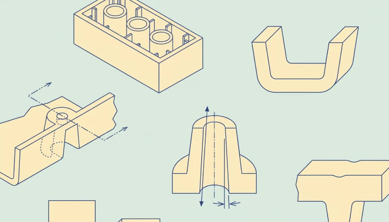
Whenever you have a part that changes wall thickness, you need to make sure you have a nice transition between the parts. You can do this by putting chamfers on your angled edges or corners. Similarly, using fillets on your fillets or corners will make sure that the molten plastic fills the mold completely and cools evenly.
Parting Line
The parting line3 is where the two halves of the mold meet to make the final product. If there is any mismatch or misalignment in the parting line design, it can cause flash defects in the molded part. So, it is important to design a simple and straight parting line to minimize these defects. Simple parting lines are easier to make, require less maintenance, and can give a better overall finish to the final product.
When you’re designing a parting line, it’s usually best to put it on a sharp edge rather than on a rounded surface. This helps you avoid having to use molds with tight tolerances, which can drive up your production costs. You also want to think about how the parting line will look on the finished product.
You want to design it so that it’s as invisible as possible and doesn’t go across any critical surfaces or features, like text or logos. This will help you make sure that your finished product looks the way you want it to and will help you make better parts with injection molding.
Draft Angles
The draft angle on the surface of an injection molded part allows for easy removal from the mold without damage. The required draft angle depends on factors such as wall thickness, material shrinkage, post-processing finishing needs, etc.
The average draft depth should increase by 1 degree per inch of depth, but at least 1.5 to 2 degrees is usually safe for most parts. Heavy textures may require up to 5 degrees per inch of depth. Inadequate draft can lead to cosmetic defects such as drag marks.
You can add draft angles when designing injection molded parts using a CAD system. However, it is best to do this in the final stages of the design to minimize complexity.
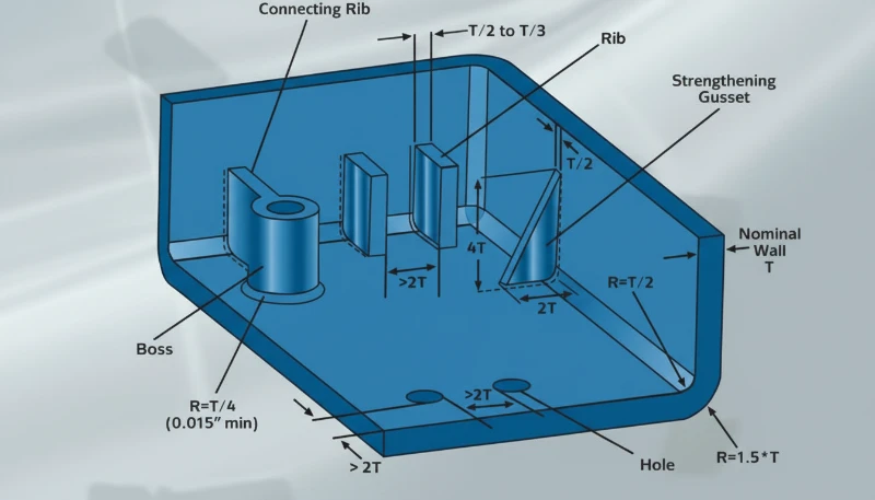
Ribs and Bosses
Ribs are used to strengthen the walls of parts where two walls meet at a 90-degree angle. They help make the part stronger and able to hold more weight. Bosses are raised areas on a part that are used to attach and line up other parts. They also make the part stronger in areas like screw holes and slots.
The base thickness of the support ribs should be no more than two-thirds of the thickness of the adjacent wall. The rib height should not exceed 2.5 times the nominal wall thickness (2.5T). Shrinkage must be taken into account. To avoid sink marks, the thickness of the boss should not exceed 60% of the overall wall thickness.
Gate Location and Types
The gate in injection molding is a very important part that is directly connected to the plastic part and controls the flow of molten plastic resin into the cavity. The size, shape, and location of the gate have a big impact on the finished product. It affects how strong it is and how it looks.
There are four common types of gate designs used in different kinds of injection molds: edge, sub, hot tip, and sprue. As the name suggests, edge gates are located on the edge of a flat part and leave a scar on the parting line.
Sub gates are common and come in different variations such as banana gates, smiley gates, and tunnel gates. They require ejector pins for automatic trimming and help move the gate location away from the parting line for better filling.
Hot tip gates are only used for hot runner injection molds. They are usually located at the top of the mold for round or tapered geometries. On the other hand, gates are ideal for large cylindrical single-cavity molds. They usually leave large scars at the contact points but are easy to manufacture and maintain.
The design and type of gate you use depends on the design of the part, the material you choose, the dimensions you need, and how you want the part to look. One thing to keep in mind is to put the gate in a place where it won’t cause a lot of stress or damage to the part.
You also want to avoid having to cut the part off the runner and put the gate in the thickest part of the part so it fills up good. Sometimes you need more than one gate, depending on how big the part is, what shape it is, and what kind of plastic you’re using.
Ejector Pins
This is a critical part of the injection molding setup and helps push the part out of the mold after it has cooled sufficiently. They often leave marks on the part. Therefore, you need to design them on a plane that is perpendicular to the direction of pin movement.
Part shape, draft angle, waThe gate in injection molding is a very important part that is directly connected to the plastic part and controls the flow of molten plastic resin into the cavity. The size, shape, and location of the gate have a big impact on the finished product. It affects how strong it is and how it looks.
For example, a stickier resin will require more demolding force. Likewise, a softer plastic polymer will require wider or more pins to help distribute the demolding force to avoid molding defects.
Undercuts and threads
Undercuts and threads are recessed or overhanging features that make it difficult for a plastic part to be ejected from the mold with a single pull. The design should ensure that the part can be ejected with a single, one-way pull. Doing so will help keep injection molding costs low. Therefore, it is important to avoid threads and undercuts when designing injection molded parts.
To avoid undercuts, orient features parallel to the draw line and incorporate lifters and slides into the design. Lifters help release internal undercuts without draft. After the part cools, lifters can push upward at an angle to remove undercuts from the mold. Slides, on the other hand, use angled pins attached to the core mold to release external undercuts.
Rounded Corners
To make injection molding more efficient and better quality, designers and engineers should use rounded features instead of sharp corners and edges. Sharp edges need more pressure to fill, which can damage the part and cause defects when ejecting. Rounded inside and outside corners help plastic flow better, which reduces stress and cracking.
Inside corner radius should be at least 50% of the adjacent wall thickness. Outside corners, on the other hand, should be 150% of the adjacent wall thickness. For vertical features like bosses and snap fits, the base should be rounded. Boss radius should be 25% of the adjacent wall, with a minimum radius of 0.015 in (0.381 mm).
Surface Finish
Plastic parts can have different surface finishes. These finishes affect the texture, look, and feel of the part. Choosing the right finish is important during the design phase. It determines the tools and materials needed. Rough finishes need higher draft angles.
They also affect the material you choose. You may need to prepare the mold surface to get the finish you want. Any imperfection in the mold surface will show up on the part. The more work you have to do after the part comes out of the mold, the more it will cost and the longer it will take to make the mold.
Material Selection
Injection molding is all about using different types of plastic resins, each with its own unique physical and mechanical properties. The material you choose will determine how your part performs in its intended environment. When you’re picking a material for injection molding, you need to think about things like material shrinkage, fit, and cost.
Plastic shrinkage is different for each type of plastic and the way it is processed, which can affect how the part works and how it looks. You also need to think about how well the plastic can be put together with things like screws and welding.
While it is important to have the right properties for the plastic, you also need to think about how much it costs to get the plastic, make it into a part, and finish it so you can make it for the least amount of money.
“Uniform wall thickness is crucial in injection molding design.”True
Uniform wall thickness minimizes stress and warpage, ensuring a consistent and high-quality part output.
“Draft angles are not necessary for injection molding parts.”False
Draft angles facilitate the easy release of the part from the mold, reducing the risk of damage during ejection.
What are the Guidelines for Injection Mold Design?
Effective injection mold design is crucial for producing high-quality plastic parts efficiently and consistently across various industries.
Key guidelines for injection mold design: choose suitable materials, ensure effective cooling systems, and optimize part ejection. These practices improve efficiency, reduce defects, and enhance durability in the molding process.
From our factory design reviews, the ZetarMold in-house mold manufacturing facility lets our engineers connect wall thickness, draft, gate location, cooling, and ejection decisions before steel is cut. For DFM-sensitive parts, 8 senior engineers can review tooling risk, and our production planning can compare the design against 47 injection molding machines before quoting and sampling.
Mold Base and Cavity Layout
Mold tooling is made up of a mold base, cavity, core insert, and other parts. The mold base is the foundation of the mold, while the cavity and core insert shape the part. The design of the mold tooling affects how accurate and consistent the molding process is. CNC machining achieves precise vertical vertical walls essential for intricate plastic injection molding molds.
The mold has to be tough, easy to maintain, and easy to take apart and put back together for repairs and maintenance. The mold tooling has to be made with precision to make sure the cavity and core line up right. The cavity layout of the mold frame also has to let you get to the hollow and core inserts for easy maintenance and repairs. This cuts down on defects and makes the parts better.
Cooling system design
The cooling system is a big deal in injection mold design. It controls the temperature of the mold cavity and plastic material. Cooling is important because it helps solidify the plastic and control shrinkage.
The cooling system design should ensure that the mold cavity is cooled evenly. The cooling channels should be designed close to the areas that take longer to cool so that they don’t interfere with the gate and runner system. The machinist should also optimize the design to achieve the shortest cycle time possible.
Runner and Gate Design
The runner and gate system controls how the molten plastic flows into the mold cavity. The gate is where the plastic goes into the cavity, and the runner system helps the plastic get to the gate. The design of the gate and runner system affects how well the molding process works and how good the finished product is.
The gate size, location, and shape should optimize material flow, minimize part stress, and avoid defects in the part. The runner system should minimize pressure drop, ensure even material distribution, and avoid dead spots where plastic can accumulate and cause defects.
Ejection System Design
The ejector system is what gets the part out of the mold. When you design the ejector system, you have to think about the shape of the part, how many undercuts it has, and how strong it is. You can use ejector pins, sleeves, or hydraulic ejector systems to make sure the part doesn’t get messed up when you take it out.
You also have to design the ejector system so it can take the force it needs to get the part out of the mold. You also have to think about where the ejector system goes in relation to the gate and runner system so it doesn’t get in the way.
Mold Materials and Surface Treatment
The material you use for your mold will affect how long it lasts and how good your parts look. You want a material that can take a lot of heat, spreads heat well, and doesn’t wear out. Picking the right material can help you make parts faster, make your mold last longer, and make better parts.
Every mold is different and needs to be thought about carefully when you’re making it. The materials you use have to be machined just right so you don’t get any surface defects that will show up on the part you’re molding.
You have to get rid of the marks left by the end mill on the mold surface by doing more finishing, like sandblasting or polishing. How much finishing you have to do affects how much it costs and how long it takes to make the mold.
“Injection mold design affects the cooling time of the molded part.”True
Proper mold design ensures uniform cooling, which reduces cycle times and improves part quality.
“Injection mold design has no impact on product quality.”False
Thoughtful mold design directly influences part quality by ensuring consistent material flow and uniform cooling.
What are Common Injection Molding Design Problems and Solutions?
Injection molding is a complex process with various potential design challenges that can impact product quality and production efficiency.
Common injection molding issues like warping, sink marks, and flash can be mitigated by optimizing mold temperature, adjusting cooling time, and ensuring proper venting to enhance product consistency and reduce defects.
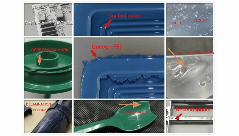
Flash
Flash is the extra plastic on the mold parting surface or ejector pin.
Causes of Flash
not enough clamping force, mold problems, bad molding conditions, exhaust system design is wrong .
Solutions
Mold design: Design the mold so it can close tightly when clamped. Check the size of the exhaust port and clean the mold surface.
Injection molding machine: set an injection molding machine with the right tonnage.
Molding process: increase injection time, reduce injection speed, reduce barrel temperature and nozzle temperature, reduce injection pressure and holding pressure.
Silver Streaks
Silver streaks are when water, air, or carbonized material is distributed on the surface of the part in the direction of flow.
Causes of Silver Streaks
The moisture content in the raw material is too high, air is trapped in the raw material, polymer degradation: the material is contaminated; the barrel temperature is too high; the injection volume is insufficient.
Solutions
Content: Dry the raw material based on the data provided by the raw material supplier before injection molding.
Mold design: Make sure there are enough vents.
Molding process: Choose the right injection molding machine and mold, clean the old material completely from the barrel when changing materials, improve the exhaust system, and lower the melt temperature, injection pressure or injection speed.
Dent
Dent is when the surface of the part is concave at the wall thickness.
Causes of Dent Formation
The injection pressure or holding pressure is too low, the holding time or cooling time is too short, the melt temperature or mold temperature is too high, and the part structure design is improper.
Solutions
Design structure: Corrugate the surface that is easy to dent, reduce the thick wall size of the part, minimize the thickness-to-diameter ratio, the adjacent wall thickness ratio should be controlled at 1.5~2, and try to make a smooth transition, redesign the thickness of the reinforcement ribs, countersunk holes and corner ribs, and their thickness is generally recommended to be 40-80% of the basic wall thickness.
For weld defects, review causes and solutions of weld marks, then adjust injection pressure, holding pressure, gate size, or gate position based on flow evidence.
Weld Mark
Weld mark is when two streams of material meet and weld together, and it causes a defect on the surface.
Causes of Weld Mark
If there are holes, inserts, or multi-gate injection molding mode in the part, or if the wall thickness of the part is uneven, weld marks may occur.
Solutions
Material:Make the plastic melt flow better.
Product design: Change the way the product is made and how thick the walls are.
Mold design: Move where the plastic goes into the mold and add places for the air to get out.
Process conditions: Make the plastic hotter and use less stuff to keep it from sticking to the mold.Scorch marks are when the air in the mold can’t get out fast enough and the plastic burns at the end of the flow.
Warping and Deformation
Warping deformation is when the shape of the injection molded thing gets all messed up and it warps all unevenly, which is not what you want. It’s one of the things that can go wrong when you’re making stuff with injection molds.
“Warping is a common issue in injection molding.”True
Warping occurs due to uneven cooling, leading to parts becoming distorted. It’s often addressed by adjusting cooling times and mold temperatures.
“Sink marks can only be fixed by redesigning the mold.”False
Sink marks can also be reduced by adjusting process parameters such as packing pressure and cooling time, alongside mold design adjustments.
What should engineers do before releasing the design?
A release-ready design is DFM-approved after checking walls, draft, gates, parting line, cooling, ejection, shrinkage, and inspection.
This will give you a detailed understanding of what you need and how to complete the process. The injection molding design rules discussed in this article will help you optimize the process, ensure cost-effective production and reduce cycle times. See our Injection Mold Complete Guide for a comprehensive overview.
Frequently Asked Questions
What is the most important rule in injection molding design?
The most important rule is to keep the part easy to fill, cool, eject, and inspect without adding unnecessary tooling complexity. Uniform wall thickness, practical draft angles, clear parting-line decisions, and realistic gate placement usually matter more than adding many small features. A design that looks acceptable in CAD can still fail in production if it creates trapped air, uneven cooling, high ejection force, or cosmetic defects. Before release, the design should be reviewed with both product function and mold manufacturing constraints in mind.
How much draft angle should an injection molded part use?
A practical starting point is to use at least 1 to 2 degrees of draft on most vertical faces, then increase the angle for deeper walls, textured surfaces, or materials that shrink tightly onto the core. The exact value depends on part depth, surface finish, resin shrinkage, and ejection direction. Draft should be added early because late changes can move parting lines, alter shutoffs, and affect appearance. If a surface must remain straight, the toolmaker should review whether polishing, ejector layout, or material choice can reduce release risk.
Why does wall thickness matter so much?
Wall thickness controls filling pressure, cooling time, shrinkage, sink marks, warpage, and material consumption. Thick areas cool slowly and can create sink or internal voids, while thin areas may short-shot or show weak weld lines if the melt freezes too quickly. The safest design usually keeps walls as uniform as possible and uses ribs, bosses, or gradual transitions instead of sudden thick sections. When thickness must change for strength, the transition should be smooth enough for resin flow and predictable cooling.
When should a design use ribs instead of thicker walls?
Ribs are useful when the part needs stiffness but a thicker wall would create sink marks, longer cooling time, or excess material cost. A rib should normally be thinner than the adjacent wall, include draft, and connect with enough radius to avoid stress concentration. Ribs also need spacing so steel can be manufactured and polished properly. If a feature needs both strength and a cosmetic surface, rib placement should be reviewed against gate location, flow direction, and potential read-through marks on the show side.
What should buyers ask a supplier before tooling starts?
Buyers should ask whether the supplier has reviewed wall thickness, draft, parting line, gate location, ejector placement, cooling layout, material shrinkage, tolerance stack-up, and cosmetic expectations before steel is cut. They should also ask which risks require DFM changes and which can be handled during sampling. A clear review before tooling is cheaper than correcting a finished mold after defects appear. For production parts, the supplier should connect design decisions with cycle time, inspection method, maintenance access, and expected tool life.
Need a Quote for Your Injection Molding Project?
Get competitive pricing, DFM feedback, and production timeline from ZetarMold’s engineering team.
Request a Free Quote → Use our injection molding process guide for process context and our injection molding supplier sourcing guide before comparing pricing.
-
wall thickness: Wall thickness is a core design dimension that controls filling pressure, cooling time, shrinkage, sink marks, and part stiffness. ↩
-
draft angle: Draft angle refers to the taper added to vertical faces so the molded part can release from the tool without scuffing or sticking. ↩
-
parting line: parting line refers to a parting line is the visible boundary where two mold halves meet and where flash, mismatch, or cosmetic risk can appear. ↩


