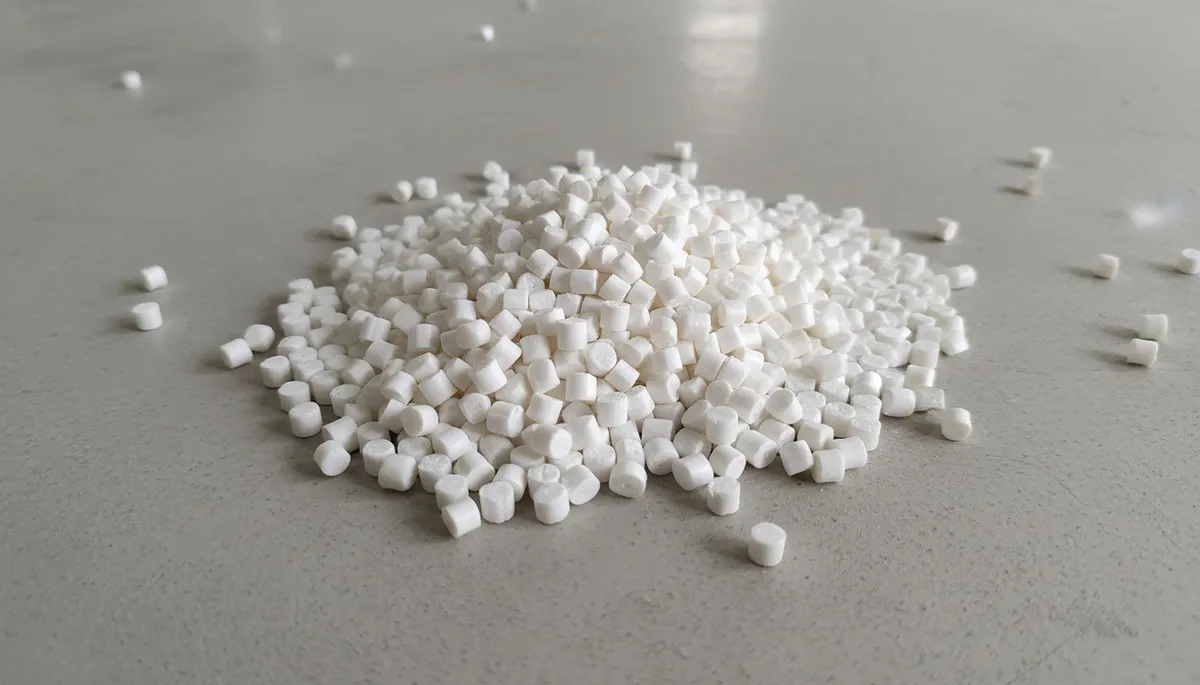
- Les systèmes à canaux chauds1s éliminent les déchets de canaux froids et réduisent la consommation de matière de 10–25% par injection dans les moules multi-empreintes.
- Un outillage à canaux chauds ajoute $5,000–$20,000 au coût du moule, mais cet investissement est amorti par les économies de matière à partir de 100,000+ pièces.
- La température du collecteur doit être régulée à ±1–2°C afin d’éviter la dégradation de la matière et le suintement au seuil entre les cycles.
- Les canaux chauds à obturateur produisent des vestiges de seuil inférieurs à 0.1 mm, contre 0.5–2 mm pour les buses ouvertes.
- Les canaux chauds nécessitent 30–60 minutes de stabilisation thermique avant la production, ce qui les rend moins efficaces pour les petites séries.
- Le temps de séjour dans le collecteur ne doit pas dépasser 5–15 minutes pour les résines thermosensibles comme le PVC et le POM.
Qu’est-ce qu’un système de canaux chauds dans le moulage par injection ?
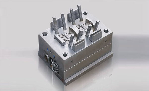
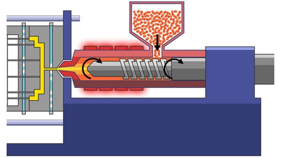
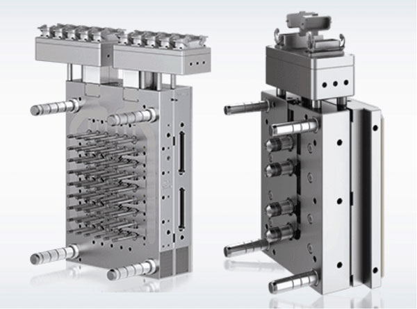
Un système à canaux chauds est un système d’alimentation thermorégulé intégré au moule d’injection, qui maintient le plastique fondu dans les canaux pendant toute la production. Contrairement à un canal froid, où le plastique de la carotte et des canaux se solidifie à chaque injection puis doit être éjecté et éliminé, celui du collecteur chaud reste à sa température de fusion complète — généralement 180–380°C — et n’est jamais éjecté. À l’ouverture du moule, seules les pièces finies sont retirées ; la matière des canaux reste fondue dans le collecteur, prête pour l’injection suivante.
Chez ZetarMold, nous installons des systèmes à canaux chauds dans environ 40% de nos nouveaux moules d’injection — principalement pour les outillages à grand volume et à longue durée de production, pour lesquels les économies de matière et la réduction du temps de cycle justifient l’investissement supérieur. Notre expérience couvre aussi bien les systèmes simples à buse ouverte et 2 empreintes que les collecteurs complexes à obturateurs et 32 empreintes destinés à l’automobile et à l’électronique grand public. Comprendre la sélection et le fonctionnement des canaux chauds est essentiel pour tout ingénieur chargé de spécifier un outillage de moulage par injection.
Composants d’un système à canaux chauds et fonctionnement
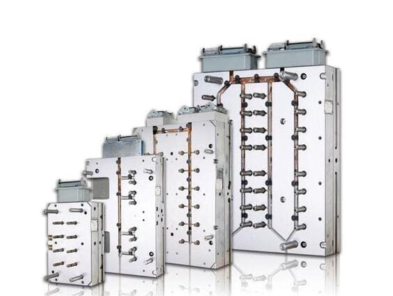
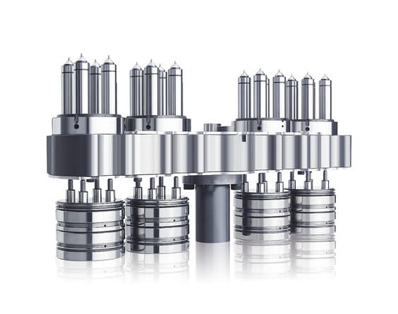
Un système à canaux chauds complet se compose de quatre éléments principaux : le collecteur, les buses de descente (également appelées descentes ou torpilles), les éléments chauffants et thermocouples, et le régulateur de température. Le collecteur est le bloc chauffé central qui reçoit le plastique de la buse de la presse à injecter et le distribue par des canaux internes à chaque buse de descente. Les buses de descente partent du corps du collecteur, traversent la plaque B du moule et positionnent la pointe du seuil au point d’entrée exact de chaque empreinte.
Des éléments chauffants — généralement des cartouches ou des résistances spiralées — sont intégrés au collecteur et à chaque buse pour maintenir la température. Des thermocouples mesurent la température en plusieurs points du système et transmettent les données au régulateur. Un régulateur moderne de canaux chauds maintient une température de ±1–2°C dans toutes les zones, compensant les pertes thermiques vers l’acier du moule et les variations de fréquence des cycles d’injection.
Dilatation thermique4 La gestion est un défi d’ingénierie critique dans la conception des canaux chauds. Lorsque le collecteur chauffe de la température ambiante (20°C) à la température de transformation (250–350°C), il se dilate linéairement de 0.015–0.025 mm par degré Celsius. Pour un collecteur de 500 mm à une température de transformation de 300°C, cela représente une dilatation totale de 2.1–3.75 mm. Le collecteur doit être monté de manière à absorber cette dilatation sans créer de contrainte sur les pointes de buse ou la structure du moule. Des plots de centrage et des logements de dilatation sont usinés dans la plaque du moule afin de permettre un mouvement contrôlé du collecteur.
La perte de charge dans le système à canaux chauds est un paramètre de conception important. Le plastique doit remplir toutes les empreintes simultanément et à pression égale — tout déséquilibre de pression entre les buses entraîne des variations dimensionnelles entre empreintes. Le diamètre des canaux du collecteur chaud (généralement 8–16 mm), leur longueur et le nombre de coudes contribuent tous à la perte de charge. Des collecteurs équilibrés (ramification symétrique en H) garantissent une résistance identique du trajet d’écoulement vers chaque buse.
Canaux chauds à buse ouverte ou à obturateur : que choisir ?
Les deux principales conceptions de buses à canaux chauds sont la buse ouverte (également appelée seuil thermique) et le point d’injection à obturateur. Les buses ouvertes reposent uniquement sur la solidification du plastique au niveau de l’orifice étroit pour assurer l’étanchéité entre les injections : à la fin de l’injection, le petit volume de plastique dans l’extrémité refroidit par conduction vers l’acier plus froid du moule et se solidifie, fermant l’empreinte. Les buses à obturateur utilisent une aiguille en acier à commande mécanique qui ferme physiquement l’orifice à la fin de l’injection et assure une étanchéité mécanique positive quelle que soit la viscosité du plastique.
Les systèmes à canaux chauds à buse ouverte sont plus simples, moins coûteux ($500–$1,500 par buse contre $1,500–$4,000 pour une obturation à aiguille) et comportent moins de pièces mobiles à entretenir. Ils conviennent à la plupart des résines courantes (PP, PE, ABS, PS) à des cadences de production modérées. Le vestige du point d’injection des systèmes à buse ouverte mesure généralement 0.3–1.5 mm de diamètre et 0.1–0.5 mm de hauteur : il est acceptable sur les surfaces non esthétiques, mais exige souvent des opérations secondaires pour les applications de classe A.
Les systèmes à canaux chauds avec obturateurs offrent l’absence de coulure, une synchronisation précise des points d’injection et une qualité supérieure du vestige d’injection — généralement inférieure à 0.1 mm. Ils sont indispensables pour les matériaux à haute viscosité difficiles à figer (PC, PEI, PA66-GF30), les applications à haute pression où des buses ouvertes couleraient sous la pression de maintien, les moules multi-empreintes nécessitant une commande séquentielle des points d’injection et les pièces esthétiques pour lesquelles l’apparence de la marque d’injection est critique. Les actionneurs d’obturateurs peuvent être pneumatiques (vérin à air), hydrauliques ou électriques à servocommande.
« Les systèmes à canaux chauds peuvent réduire le temps de cycle de 5–15% par rapport aux moules à canaux froids en supprimant le temps nécessaire à la solidification du système de canaux. »True
Dans un moule à canaux froids, le cycle ne peut s’ouvrir avant solidification suffisante de la pièce et des canaux. Le canal, généralement de 4–8 mm, exige un temps de refroidissement important. Dans un moule à canaux chauds, ce temps disparaît puisque le canal ne solidifie jamais. Le cycle s’ouvre dès que la pièce est solide. Pour un cycle de 20 secondes à froid, le passage au chaud peut le ramener à 17–19 secondes, gain significatif à grand volume.
« Les régulateurs de température des canaux chauds sont des accessoires facultatifs : les moules peuvent fonctionner sans eux avec un réglage manuel. »False
C'est faux et dangereux. Sans régulation active, un canal chaud surchauffe en production prolongée, dégrade et brûle la matière puis bloque le collecteur. Le contrôleur est indispensable : il maintient le collecteur à ±1–2°C, prévenant surchauffe et sous-chauffe. Les contrôleurs modernes déclenchent alarme et arrêt si une zone dépasse la consigne de plus de 10–15°C.
Le choix entre une buse ouverte et un obturateur à aiguille dépend du matériau, des exigences d’aspect et du budget. Pour un moule standard de bouchons en PP à 16 empreintes, les buses ouvertes offrent des performances suffisantes à moindre coût. Pour un moule à 4 empreintes de lentilles automobiles en PC transparent, l’obturateur à aiguille est indispensable pour l’aspect du point d’injection et la maîtrise du remplissage. Dans notre processus de conception des moules d’injection, nous définissons le type de buse lors de la revue initiale du concept d’outillage, et non après la fabrication du moule.
Compatibilité des matériaux avec les systèmes à canaux chauds
Toutes les matières plastiques ne conviennent pas également aux canaux chauds. Le principal enjeu est le temps de séjour, durée pendant laquelle le plastique fondu reste dans le collecteur entre deux injections. Pour les matières thermosensibles, un séjour excessif entraîne dégradation, décoloration et perte de propriétés mécaniques. Le PVC, le POM (acétal) et certains grades ignifugés se dégradent rapidement au-dessus de leur plage de transformation ; ils exigent des systèmes minimisant le séjour et permettant une purge rapide à l’arrêt.
Le temps de séjour se calcule en divisant le volume du collecteur par le volume injecté à chaque cycle. Pour un collecteur de 200 cm³ traitant 50 cm³ par cycle, le temps de séjour est de 4 injections ; avec un cycle de 30 secondes, le temps de séjour moyen est de 2 minutes. C’est acceptable pour le POM, qui commence à se dégrader après 5–8 minutes à 200°C. Pour le PVC au-dessus de 200°C, même 2 minutes de séjour peuvent libérer du HCl et corroder le moule, ce qui rend les canaux chauds risqués avec les nuances de PVC standard.
Haute performance thermoplastiques comme le PEEK, le PPS et le LCP exigent des systèmes à canaux chauds spécialisés dotés de corps de buse en incoloy ou en titane, car les composants standard en acier à outils se corrodent rapidement aux températures de transformation du PEEK de 360–400°C. Ces buses haut de gamme coûtent 2–3× plus cher que les systèmes standard. Transformer du PEEK dans un canal chaud standard en acier P20 n’est pas viable : la combinaison de la température, de l’abrasivité et de l’activité chimique détruirait la buse en quelques milliers de cycles.
Le changement de couleur est plus difficile dans un moule à canal chaud. Avec un canal froid, la nouvelle couleur purge le système en 2–3 injections, car le canal est éjecté à chaque cycle. Avec un canal chaud, l’ancienne couleur reste dans le collecteur et exige 10–50 injections de nouvelle matière selon la géométrie des canaux et l’efficacité du produit de purge. Pour une production très diversifiée avec changements fréquents, le canal froid peut être plus pratique malgré les déchets.
Économie des canaux chauds : quand l’investissement est-il justifié ?
La rentabilité des canaux chauds repose sur trois économies : suppression des déchets de canaux, suppression de leur refroidissement et réduction de la gestion du rebroyé. Pour un moule 16 empreintes produisant des pièces de 10 grammes avec 3 grammes de canal froid par empreinte (48 grammes par cycle), le canal chaud économise 48 grammes. À 1,000 cycles/heure et $4/kg, cela représente $115/heure, soit $276,000/an en une équipe.
Un outillage à canaux chauds coûte $5,000–$20,000 de plus, mais les économies annuelles de matière de l’exemple ci-dessus amortissent l’investissement en moins d’un mois. Cette rentabilité explique la généralisation des canaux chauds pour les moules de grande série à longue durée de production. Pour les moules exécutant moins de 100,000 cycles au total, l’intérêt économique devient marginal : les économies de matière peuvent ne pas compenser le surcoût de l’outillage et de la maintenance du système à canaux chauds.
Le coût de maintenance est réel, mais maîtrisable. Les systèmes à canaux chauds exigent une maintenance périodique : remplacement des éléments chauffants (tous les 500,000–2,000,000 cycles), étalonnage annuel des thermocouples, nettoyage des pointes de buse et nettoyage occasionnel des canaux du collecteur. La maintenance annuelle d’un système à canaux chauds à 16 points coûte généralement $500–$2,000 — un montant modeste face aux économies de matière, mais à budgéter. Notre usine conserve des éléments chauffants et des thermocouples de rechange pour tous les systèmes à canaux chauds afin de réduire les arrêts imprévus.
“Pour les résines techniques, les économies de matière des systèmes à canaux chauds amortissent généralement l’investissement supplémentaire dans l’outillage en 50,000–200,000 cycles de production.”True
Le calcul d’amortissement est simple : divisez le surcoût du canal chaud ($5,000–$20,000) par l’économie de matière par cycle. Pour un moule 4 empreintes produisant des pièces de 50 grammes avec un canal de 15 grammes par empreinte en nylon à $4/kg, les déchets coûtent $0.24 par cycle. Un surcoût de $10,000 s’amortit en 41,667 cycles. À 500 cycles/heure en deux équipes, cela représente environ 6 semaines. Une matière plus chère et des canaux plus grands accélèrent fortement l’amortissement.
“Les systèmes à canaux chauds peuvent être installés dans n'importe quel moule d'injection sans modifier la structure du moule.”False
Les systèmes à canaux chauds ne peuvent pas être ajoutés aux moules à canaux froids existants sans modifications majeures. Le collecteur exige un espace dédié dans la plaque A, généralement 50–100 mm de hauteur d’empilage. Les logements de buses doivent être usinés avec précision aux tolérances exactes (±0.01 mm). Le refroidissement doit être reconçu pour éviter un refroidissement excessif du collecteur tout en maintenant celui des empreintes. Les seuils peuvent devoir être déplacés selon la géométrie des buses. Dans la plupart des cas, convertir un moule à canaux froids coûte autant qu’un nouveau moule ; cela ne se justifie que dans des situations très précises.
Dépannage des canaux chauds : problèmes courants et solutions
Le filage au seuil, c’est-à-dire la fuite de plastique par la pointe entre deux injections, est le problème de production le plus courant des canaux chauds. Il survient lorsque la température de la pointe est trop élevée, empêchant la solidification entre les injections, lorsque la pression de maintien est relâchée trop tôt ou lorsque le jeu entre la buse et le moule est excessif. Les solutions consistent à réduire la température de buse par paliers de 5°C, prolonger le maintien et vérifier le jeu seuil-pointe de buse, généralement de 0.03–0.07 mm.
La panne d’un élément chauffant est l’incident d’entretien le plus courant des canaux chauds. Les cartouches tiennent 500,000–2,000,000 cycles selon la température, les cycles thermiques et l’humidité. Une panne refroidit la zone sous la température de transformation et provoque manques ou blocage des empreintes. Notre protocole surveille le courant à chaque démarrage : une baisse de 20% signale une fin de vie proche.
Des points noirs dans les pièces issues d’un moule à canaux chauds signalent une dégradation dans le collecteur : surchauffe locale, stagnation en zone morte ou contamination au changement de couleur. Le diagnostic consiste à réduire la consigne zone par zone en surveillant la fréquence, purger avec un inhibiteur puis, si nécessaire, démonter et nettoyer le collecteur. Notre équipe documente chaque événement et sa cause pour prévenir toute récidive.
Pour les moules exigeant les meilleures performances de canaux chauds — commande séquentielle des obturateurs pour de grandes pièces automobiles, co-injection multimatériau ou micromoulage à très faible poids injecté — nous prescrivons des actionneurs électriques asservis avec retour de position. Ils permettent de programmer indépendamment le moment d’ouverture, la position et la vitesse de chaque obturateur, autorisant une optimisation du remplissage impossible avec des systèmes pneumatiques. Le surcoût de $500–$2,000 par actionneur est justifié par l’amélioration de la qualité et de la maîtrise du procédé pour les applications critiques.
| Facteur | Choisir les canaux chauds | Choisir un canal froid |
|---|---|---|
| Volume de production | 100,000+ pièces | Moins de 50 000 pièces |
| Coût des matériaux | Élevé (>$3/kg) | Faible (<$2/kg) |
| Changements de couleur | Rare (même couleur de production) | Changements de couleur fréquents |
| Apparence de la porte | Classe A, pas de vestige | Non cosmétique acceptable |
| Matériau sensible à la chaleur | Temps de séjour faible OK | Purge complète à chaque cycle |
| Budget d’outillage | >15 000 $ au total | <$10,000 au total |
| Priorité du temps de cycle | Vitesse maximale nécessaire | Temps de cycle moins critique |
Pour les clients qui évaluent moulage par injection de faibles volumes options, les systèmes à canaux froids dans les outillages en aluminium sont presque toujours plus appropriés que les systèmes à canaux chauds. L’investissement dans un canal chaud ne se justifie pas pour des séries inférieures à 50,000 pièces, et la complexité de sa maintenance n’est pas adaptée à un environnement de production en petite série.
Questions fréquemment posées
Quelle est la différence entre un système à canaux chauds et un système à canaux froids ?
Un système de canal chaud maintient le plastique dans les canaux de coulée à l’état fondu tout au long du cycle de production grâce à des éléments chauffants internes et des régulateurs de température, donc aucun matériau de coulée n’est éjecté à chaque tir. Un système de canal froid utilise des canaux non chauffés où le plastique se solidifie à chaque cycle et est éjecté avec les pièces moulées, créant un déchet de coulée de 10 à 25% du poids de l’injection. Les systèmes de canal chaud éliminent ce déchet, réduisent le temps de cycle de 5 à 15% et améliorent la constance des pièces en maintenant une température de fusion constante à chaque porte. Le compromis est un coût d’outillage plus élevé (5 000 à 20 000 $ supplémentaires) et des exigences de maintenance plus complexes. Les canaux froids sont plus simples, moins chers et mieux adaptés à la production intensive en changements de couleur ou aux matériaux sensibles à la chaleur qui doivent être entièrement purgés à chaque cycle.
Comment choisir entre un système à pointe ouverte et un système à vanne pour les canaux chauds ?
Choisissez un canal chaud à pointe ouverte pour les résines de commodité (PP, PE, ABS, PS) dans des applications non cosmétiques où un vestige de porte de 0,3 à 1,5 mm est acceptable, les vitesses de production sont modérées et le budget est une contrainte. Les buses à pointe ouverte coûtent 500 à 1 500 $ chacune et ont moins de pièces mobiles à entretenir. Choisissez des canaux chauds à valve pour les résines techniques à haute viscosité (PC, PA-GF, PEI), les applications cosmétiques où la marque de porte doit être inférieure à 0,1 mm, les moules multi-cavités nécessitant un contrôle séquentiel des portes, ou les applications où la bavure de pointe ouverte est un risque qualité. Les buses à valve coûtent 1 500 à 4 000 $ chacune mais assurent une fermeture mécanique positive de la porte, éliminant les bavures et permettant un contrôle précis individuel de chaque cavité. En cas de doute, spécifiez une valve — les avantages qualité justifient généralement la différence de coût pour des volumes de production supérieurs à 100 000 cycles.
Quels matériaux ne conviennent pas aux systèmes à canaux chauds ?
Plusieurs familles de matériaux posent problème aux canaux chauds standard. Le PVC surchauffé libère de l’acide chlorhydrique qui corrode collecteurs et buses en acier à outils ; il exige des canaux froids sauf composants anticorrosion spécialisés. Le POM (acétal) se dégrade en formaldéhyde gazeux au-dessus de 230°C, avec risque de surpression. Les grades ignifugés halogénés se dégradent souvent dans les zones mortes et créent des points noirs. Les matières chargées à plus de 40% de verre ou minéraux usent excessivement les pointes standard et exigent des inserts trempés. Consultez toujours le guide du moulage par injection afin de vérifier la compatibilité avec un canal chaud avant de spécifier un système à canaux chauds.
Combien de temps faut-il pour qu’un système à canaux chauds se stabilise avant la production ?
Les systèmes de canal chaud nécessitent généralement 30 à 60 minutes de préchauffage avant d’atteindre l’équilibre thermique et d’être prêts pour la production. Pendant cette période de chauffage, le collecteur et les buses doivent atteindre progressivement leurs températures de consigne — un chauffage rapide peut provoquer un choc thermique dans les éléments chauffants et une dilatation inégale qui sollicite les connexions buse-collecteur. Les régulateurs de température modernes utilisent des profils de montée lente (30 à 60 minutes de l’ambiante à la consigne) pour protéger les composants du système. Après avoir atteint la consigne, un temps de maintien supplémentaire de 10 à 20 minutes permet à la température de s’égaliser dans toute la masse du collecteur avant la première injection. Ce temps de démarrage rend les canaux chauds moins efficaces pour les plannings de production avec des cycles fréquents de démarrage/arrêt, ce qui renforce pourquoi ils sont mieux adaptés aux séries de production longues et continues.
Quel entretien un système de buse chaude nécessite-t-il ?
La maintenance des canaux chauds comprend des composantes planifiées et non planifiées. La maintenance planifiée inclut l’inspection et le remplacement des éléments chauffants tous les 500 000 à 2 000 000 cycles (ou lorsque la consommation de courant baisse de plus de 20%), la vérification de l’étalonnage des thermocouples annuellement, l’inspection et le nettoyage des pointes de buse tous les 100 000 à 500 000 cycles, la vérification de la décharge de pression du collecteur et l’inspection des connecteurs électriques pour la corrosion. La maintenance non planifiée répond à des problèmes spécifiques : bavure de la porte (ajuster la température, vérifier l’écart de la pointe), particules noires (purger le collecteur, vérifier les zones mortes), courts-circuits dans des cavités spécifiques (vérifier le chauffage de cette zone) et blocage de l’aiguille de la porte à valve (nettoyer l’alésage de l’aiguille, vérifier la pression de l’actionneur). Maintenir un kit de pièces de rechange avec des éléments chauffants, des thermocouples et des pointes de buse de remplacement pour chaque système de canal chaud réduit les temps d’arrêt imprévus. Le coût annuel de maintenance pour un système à 16 buses est typiquement de 1 500 à 2 000 $.
système à canaux chauds : Un système à canaux chauds est un ensemble de collecteur et de buses thermorégulé, installé dans un moule d’injection, qui maintient le plastique fondu à la température de transformation pendant tout le cycle de production et élimine les déchets de canaux froids en empêchant la solidification des conduits d’alimentation entre les injections. ↩
collecteur : Un collecteur est un bloc d’acier chauffé intérieurement dans un système à canaux chauds ; il distribue le plastique fondu depuis la buse de la presse à injecter vers chaque buse de descente et est maintenu à 180–400°C selon la matière transformée. ↩
seuil à obturateur : Un seuil à obturateur est une conception de buse à canal chaud qui utilise une aiguille actionnée mécaniquement pour ouvrir et fermer physiquement l’orifice du seuil, assurant un contrôle précis du moment de remplissage, la suppression du vestige de seuil et le contrôle individuel des empreintes dans les moules multi-empreintes. ↩
dilatation thermique : La dilatation thermique désigne l’augmentation dimensionnelle du collecteur et des buses du canal chaud lorsqu’ils passent de la température ambiante à celle de transformation, généralement 0.015–0.025 mm/°C pour l’acier à outils. La conception du montage du collecteur doit l’absorber afin d’éviter tout dommage. ↩
Obtenez des prix compétitifs, un retour DFM et un calendrier de production auprès de l’équipe d’ingénierie de ZetarMold.
Demandez un devis gratuit → Consultez notre Guide complet du moule d’injection pour une vue d’ensemble complète.