 Skip to content

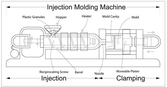
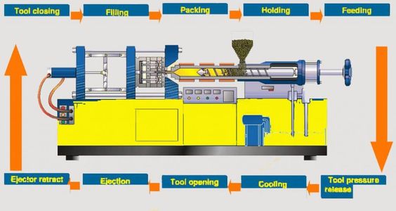
Plastic injection molding is a process in which parts are manufactured by injecting molten plastic into a mold.
Plastic injection molding process is the process of injecting molten plastic material into a metal tool which then cools and ejects a plastic part from the injection molding press.
Plastic resin is fed into the loader in pellet form. The material is rotated forward by the screw and makes contact with the heated barrel. Friction and the heated barrel melt the plastic, which accumulates in front of the screw.
The molten plastic is injected into the mold under high pressure and is then allowed to cool and cure. The result is a injection molded part. To create molds that produce quality products, it is important to understand the different types of structures used in injection molds.
Before we start to process and manufacture a plastic mold, we need to design the mold according to the drawing, which is the structural design of the mold. When it comes to mold structure, although the specific structure of each mold varies according to the product, on the whole, we can still make a general classification.

A complete mold usually consists of two main parts
The molding part, also known as the old kernel, is the part that relates to the shape and size of the plastic product.
The mold frame part, also known as the mold embryo, is used to install and fix the molding part.
Plastic injection molds are divided into two major types
(a) Two-plate mold
Two-plate mold does not apply to the mold with front mold slider and the mold with point gate, except for these two structures, all other structures and gluing methods can be used.
(b) Three plates are type mold
It’s also called fine spout mold, according to the type, and divided into the fine spout, simplified fine spout, and false three plates three forms.
The simplified type fine water mouth mold frame has no guide pillar in the side plate of the back mold, no limit washer on the tie bar, can’t design push plate structure, usually used in 500mm under the small and medium-sized mold, the product batch is not suitable for use.
(c) False three-plate mold
False three-plate mold frame is specially designed for the mold of front mold slider mechanism, there is no unloading plate, not suitable for the mold of point sprue.
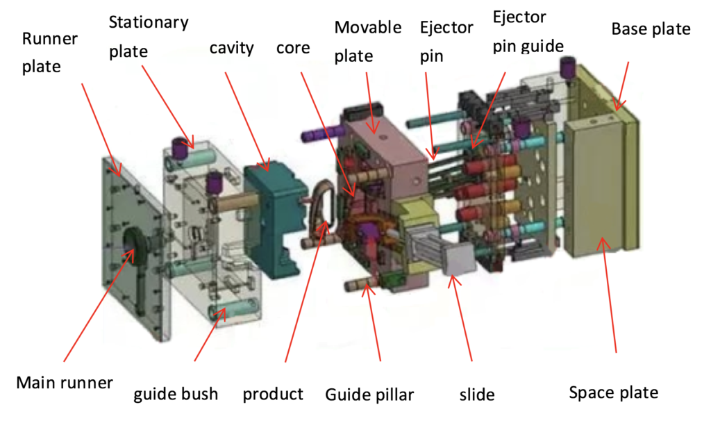
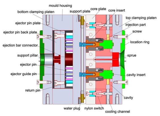
Seven major systems make up a complete plastic injection mold
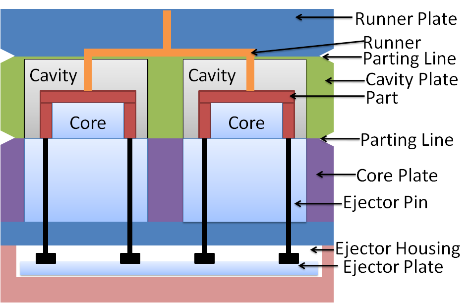
(1): The pouring system
Consists of 4 parts: the main flow channel, manifold, gate, and cold cavity.
(2) Molding mechanism
The molding structure is the part that is in direct contact with plastic products, including the front and rear mold kernel, insert, slider, slant top, and other institutions.
(3) Ejection System
The ejecting system includes the ejector pins, ejector blocks, ejector sleeve, and lifters, etc. to push the injection molded parts away from the core of the cavity after cooling.
(4) Guide structure
The guiding mechanism includes a guide pillar, guide sleeve, ejector plate reset bar, ejector plate guide bush, and other institutions.
For the more demanding mold, sometimes should additionally increase the auxiliary guiding mechanism, such as taper, straight surface, cone precision positioning, etc.
(5) Cooling system
The cooling system is mainly a circulating water circuit, with oil cooling, water cooling, air cooling, etc.
Some molds need to be heated, the cooling water circuit can be used for heating.
The mold itself is a large cooling system. To achieve a better cooling effect, one or more groups of cooling channels will be designed for the mold.
Usually, the distance between the cooling channel and the product is twice the diameter of the channel.
(6) Exhaust system
Mainly have exhaust slot, exhauinjectionst needle, exhaust inlay, exhaust valve, and other parts of the institution.
(7) Feed System
The feed system refers to the passageway through which the molten plastic passes from the nozzle of the injection machine into the mold cavity.
It consists of four parts: sprue, runner, gate, and cold slug well.
According to the requirements of process and manufacturing, some of the mold core and the female mold is composed of several pieces, and others are made into a whole.
And mold inserts are only used in the parts which are vulnerable or intractable.
To meet the requirements of in the injection molding process for the temperature of the mold, it is necessary to install a temperature-regulating system to adjust the temperature of the mold.

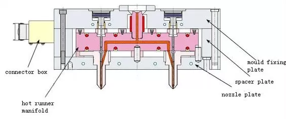
Plastic mold hot runner system introduction
(1) Hot runner system is a very widely used plastic molding casting system, mainly with the help of heating devices and an electronic temperature control system so that the molten plastic in the casting system does not solidify.
This allows the plastic to be filled into the mold cavity in a smooth and orderly manner.
In the absence of injection pressure, the molten plastic will not flow automatically, and will not be pulled, overflowed and other phenomena with the release of plastic products, so the hot runner mold is also called no runner or less runner mold.
(2) Hot runner molds have a wide range of plastic melting temperatures. Good fluidity at low temperature: good thermal stability at high temperature.
Sensitive to pressure, no flow without pressure, flow immediately after pressure; good thermal conductivity, fast heating, fast cooling.
The disadvantages are that the mechanism takes up a lot of space, has a high cost, has serious heat loss, is difficult to control, and has serious thermal expansion after heating.
Thermoplastic material, by contrast, is a plastic material that can be melted, col, aandsolidify, and then be melted again without burning.
With thermoplastic materials, they can cycyclend are used again. Sometimes this happens right on the factory floor.
(3) The design of hot runner mold needs to pay attention to the hot runner system and the mold between, must leave enough space for a tapping expansion, try to avoid large-area contact, mold and injection molding machine should be increased between the thermal insulation pad to reduce heat loss.
The insulation pad must be an insulating material, commonly used are bakelite, various plastic plates or glass fiber, etc.
(4) The hot runner system is mainly composed of four parts: main thermostat, crossover sleeve, manifold, and hot nozzle. The form of the glue inlet can be divided into the single-point type and multi-point type.
Slider mechanism and inclined top mechanism
a. Slider mechanism
(1) Slider mechanism, also called lateral parting and core extraction mechanism, is a way to deal with the barbs of plastic products that cannot be released smoothly in the mold.
When the side of the plastic product has side concave such as a round hole, release hole, tab, groove, bar, etc., and cannot be released smoothly according to the mold opening direction, the lateral parting, and core extraction mechanism must be used, and the slider mechanism is the most common form.
(2) When designing the slider, to make the inclined column drive the slider movement safely and smoothly, and not to make the inclined column and slider self-lock or bite in the process of mold opening and closing, so the angle of the inclined column must be larger than the angle of the slider locking block 1-3 degrees.
(3) The angle of the slider should not be greater than 25 degrees. When subject to the shape of the product must be greater than 25 degrees, should be used with caution.
b. Slanting top mechanism
(1) The role of the slant top is the same as the slider. Its movement principle is also the vertical movement of mold opening and closing into horizontal movement, to complete the lateral core extraction.
The inclined top mainly relies on the movement of the ejector plate and movement. It is an extension of the ejector system and belongs to the lateral core extraction mechanism.
During the movement of the inclined top, it not only can extract the barbs, but also can help the ejector mechanism eject the plastic products from the mold, so there is no need to arrange the ejector within 10-20mm around the inclined top.
(2) Ejecting stroke: In the design of the slanting top, the ejector stroke must ensure the safe ejection of plastic products from the injection mold.
To ensure the safe release of the mold at the same time, should also try to shorten the ejector stroke, the larger the ejector stroke, the easier to fatigue the slant top, the shorter the life.
(3) The angle of the inclined top should not be greater than 12 degrees. Greater than the should be used with caution. The larger the angle of the slanting top, the worse the strength, the easier it to break.
The rear mold slider, slant top mechanism is the most common and one of the most basic structures in plastic mold.
c. Front mold slider structure
Like the back mold slider, it is an important system in the plastic mold. The front mold slider mechanism is needed when the product has the following conditions.
(1) Shell products with high requirements on appearance, when there are holes or grooves on the sidewalls, the use of a rear mold slider will affect the appearance.
(2) The height of the product is very high, when the position of the buckle is far from the rear die kernel, the rear die slider is more difficult to do, need to consider using
(3) Some shell products, the location of the buckle in the front side of the internal mold, simply can not do the rear mold slider
(4) In Some products, due to the appearance of restrictions, the product appearance of the release slope is small, easy to stick to the front mold
(5) For some round, nearly round, or rectangular deep cavity products, when the entire exterior has a chamfer, try to consider using the Haff type slider.
There are many kinds of front die sliders, and the injection molding processing cost is much higher and the processing is much more difficult, therefore, in the mold design, try not to use front die sliders.
Injection the product has the undercut or sidewall hole, the custom plastic mold needs to design the side core pulling mechanism (also called the slide), the inclined core pulling mechanism (also called the lifters), the oil cylinder (when the side core pulling distance is long).
Front die slider compared with back die slider
(1) The front part of the mold with the front mold slider needs one more parting (except for the front slider), and the whole mold needs at least two or three partings. If it is a mold with point gate feeding, it needs three times; if it is a mold with non-point gate feeding, it needs two times.
(2) Whether two or three times, the main parting surface must be opened at the last time
(3) Main parting surface has more clamping mechanism
(4) The guide pillar of the mold frame is usually in the front mold
(5) Individual mold of front mold slider mechanism can not realize the structure of rear mold push plate
When designing the mold of the front mold slider mechanism, the following issues should be noted
(1) When designing the mold of the front mold slider mechanism, if the glue feeding method is point gate feeding, the fine spout mold holder or simplified fine spout mold holder must be used.
If the gluing method is non-spot gating, you must use the false three-plate mold holder, because the false three-plate mold holder is designed for the mold of the front mold slider mechanism.
(2) The main parting surface must have a very safe and reliable clamping mechanism, commonly used are nylon opener, spring clasp machine, mechanical clasp machine, etc.
(3) There must be a very safe limiting mechanism between the upper code template and some plates, commonly used with shoulder screws (limiting screws).
(4) The gate sleeve of the front mold slider mechanism mold and the front mold kernel is in a state of violent friction for a long time, so the front end of the gate sleeve must be beveled to fit.
Need a Quote for Your Injection Molding Project?
Get competitive pricing, DFM feedback, and production timeline from ZetarMold’s engineering team.
Request a Free Quote → See our Injection Molding Complete Guide for a comprehensive overview.


