 Skip to content

- The sprue is the primary vertical channel connecting the machine nozzle to the runner system.
- Runners distribute molten plastic horizontally from the sprue to each gate and cavity.
- Cold runner systems generate waste scrap; hot runner systems eliminate sprue and runner waste.
- Proper runner balancing ensures uniform fill pressure across all cavities in a multi-cavity mold.
- Gate location and runner geometry directly affect part quality, cycle time, and material waste.
What Is the Difference Between a Sprue1 and a Runner?
The sprue is the main vertical channel that connects the injection molding machine nozzle directly to the mold; the runner is the horizontal branching network that distributes melt from the sprue to each individual gate3. A sprue has a single entry point and a tapered bore (typically 3–7 mm diameter), while runners are machined into the mold parting line and branch to feed multiple cavities simultaneously.
In our factory, understanding this distinction is fundamental to gating design. The sprue sets the pressure entry point; the runner balances flow to all cavities; the gate controls fill rate and freeze-off sequence. Errors at any level—oversized sprue, unbalanced runners, or mislocated gates—cascade into part defects ranging from short shots to excessive flash.
What Is a Sprue and How Does It Work?
A sprue is a tapered cylindrical channel bored through the sprue bushing, which is located at the mold’s center and aligned with the machine nozzle. The taper (typically 1°–3° included angle) allows the solidified sprue slug to pull free during mold opening. The sprue bushing is hardened steel, ground to a matching radius that seats against the machine nozzle to prevent melt leakage.
During injection, molten plastic enters the sprue at the machine nozzle tip, flows downward through the tapered bore, and enters the runner system2 at the sprue’s base. The sprue cools last in a cold runner system because it has the largest cross-section. This extends cycle time compared to hot runner designs, where a heated manifold replaces the cold sprue entirely.
“An oversized sprue is better because it guarantees full cavity fill.”False
An oversized sprue increases material waste and extends cycle time — the sprue is the last element to solidify in a cold runner system due to its large cross-section. The entrance diameter should be only 1 mm larger than the nozzle orifice. Oversizing adds cooling time every cycle without improving fill quality.
“A correctly sized sprue reduces cycle time and minimises material waste.”True
Sizing the sprue entrance 1 mm larger than the nozzle orifice prevents flow restriction while keeping the slug volume small. A proper 1°–3° taper ensures clean ejection without sticking in the bushing. These two dimensions — entrance diameter and taper angle — are the most critical sprue design parameters.
Sprue dimensions are critical. An undersized sprue creates high pressure drop4 and fill restrictions; an oversized sprue increases material waste, extends cycle time, and may create a cosmetic witness mark if the sprue puller pin leaves a scar. In our factory, we size the sprue entrance diameter to be at least 1 mm larger than the machine nozzle orifice to prevent flow restriction while minimizing waste.
The sprue puller pin is a feature opposite the sprue bushing that retains the solidified sprue slug on the ejection side of the mold during opening, ensuring clean separation. Without a properly designed sprue puller, the sprue may stick in the bushing, halting production. Cold slugs from the sprue-nozzle interface are captured by a cold-slug well at the sprue base, preventing cold material from entering the runner and cavities.
“The sprue taper is essential for allowing the solidified slug to eject cleanly from the sprue bushing.”True
Without taper, the solidified sprue grips the bushing walls by mechanical interference, causing it to stick. A 1°–3° draft on the sprue bore provides the release geometry needed for reliable automatic ejection every cycle.
“The sprue must always be located at the geometric center of the mold.”False
Sprue location is determined by the machine’s tie-bar spacing and nozzle position, not by the mold’s geometric center. For side-gated molds or multi-cavity molds with asymmetric layouts, the sprue may be offset from center as long as it aligns with the nozzle axis.
What Is a Runner System and What Types Exist?
The runner system is the network of channels machined into the mold parting line (or in a separate runner plate) that carries melt from the sprue base to the gates of each cavity. Runner cross-sections are typically full-round (ideal for flow efficiency), trapezoidal (easy to machine in one mold half), or half-round. Full-round runners have the lowest pressure drop per unit length and are preferred for demanding applications.
Runner systems fall into two primary categories. Cold runner systems keep the runner at ambient mold temperature, allowing the plastic to solidify each cycle and producing runner scrap that must be ground and recycled or discarded. Cold runners are simpler and cheaper to build but generate material waste of 10–30% of total shot weight. Hot runner systems maintain the runner at melt temperature using electric heater cartridges and thermocouples, eliminating runner scrap and reducing cycle time by 10–30%.
Within cold runner systems, naturally balanced layouts (like H-tree or radial runners) ensure equal runner length from sprue to each gate, producing uniform fill pressure across all cavities. Artificially balanced runners use asymmetric channel diameters to equalize fill despite unequal path lengths. For critical multi-cavity molds, our factory uses Melt Flipper technology or MeltFusion runner balancing to eliminate cavity-to-cavity variation caused by shear-induced melt imbalances.
Runner diameter must be sized based on material flow length, shot weight, and cycle time targets. General guidelines specify runner diameters of 4–10 mm for most commodity resins. Undersized runners cause excessive pressure drop, fill imbalance, and degraded surface quality. Oversized runners waste material and increase cycle time. Our mold flow analysis service optimizes runner diameter, length, and branching geometry to minimize waste while ensuring balanced fill.
“Hot runner systems eliminate runner scrap and reduce cycle time compared to cold runner molds.”True
By maintaining the runner at melt temperature, hot runner systems prevent solidification between shots. This eliminates runner material waste entirely and removes the cooling time needed to solidify the runner, reducing cycle time by 10–30%.
“Hot runner systems are always the best choice for multi-cavity injection molds.”False
Hot runner systems add $5,000–$30,000 to tooling cost and require more complex maintenance. For low-volume runs (< 50,000 parts), heat-sensitive materials, or applications where color changes are frequent, cold runner systems remain more economical and practical.
How Does the Gate Connect the Runner to the Cavity?
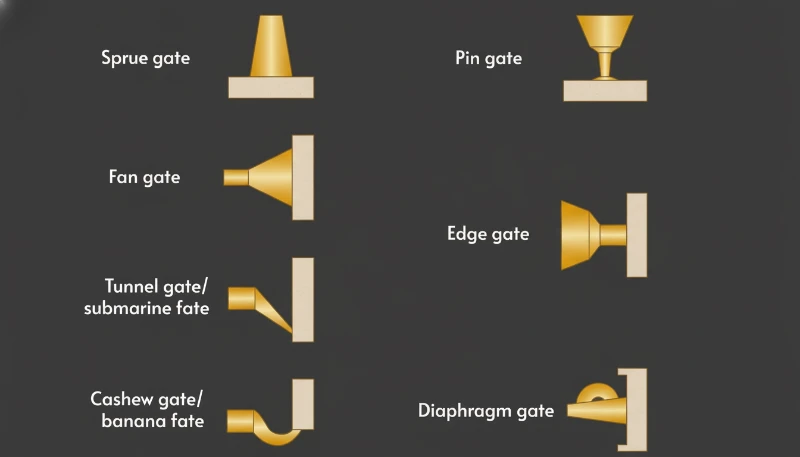
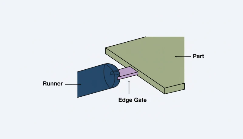
The gate is the restricted opening at the end of the runner that controls material entry into the cavity. Gate size, location, and type profoundly affect part quality. Typical gate types include edge gates (simple, versatile), submarine gates (self-degating, hidden on part), pin gates (small point entry, used in hot runner systems), fan gates (for wide, flat parts), and film gates (thin film across entire edge for stress-free fill).
Gate sizing follows the rule that gate cross-section should be 50–80% of the wall thickness at the gate location. Undersized gates cause jetting, excessive shear heating, and premature freeze-off before the cavity is full. Oversized gates leave visible vestige marks and require longer hold time. Gate location should be at the thickest wall section to ensure fill flows from thick to thin, preventing air entrapment and weld line formation in critical areas.
In our factory, gate location decisions are validated using mold flow analysis before mold cutting. Simulation identifies weld line positions, air trap locations, and fill pressure distribution for proposed gate positions. By comparing alternatives in simulation, we optimize gate placement to minimize weld lines on structural features and eliminate air traps that would otherwise require manual venting operations.
Sprue vs Runner vs Gate: Key Comparison
| Feature | Sprue | Runner | Gate |
|---|---|---|---|
| Location | Vertical, center of mold | Parting line, branching | Cavity entry point |
| Cross-section | Tapered cylinder, 3–7 mm | Round/trap, 4–10 mm | 0.5–3 mm typical |
| Function | Entry from machine nozzle | Distributes melt to gates | Controls fill rate |
| Waste in cold system | Sprue slug (significant) | Runner scrap (10–30%) | Gate vestige (small) |
| Hot variant | Heated sprue bushing | Hot runner manifold | Hot tip or valve gate |
| Defect if undersized | Fill restriction, slow cycle | Pressure drop, imbalance | Jetting, short shot |
| Defect if oversized | Long cycle, large slug | Excessive waste | Visible vestige mark |
The table above clarifies that while sprue, runner, and gate all serve the purpose of delivering melt to cavities, each operates at a different scale and with different design priorities. Sprue design is driven by machine compatibility; runner design by cavity balance and material efficiency; gate design by part aesthetics, structural requirements, and fill dynamics.
How Does the Injection Molding Process Flow Through Sprue and Runner?
During injection, the sequence is: machine nozzle → sprue → primary runner → secondary runner → gate → cavity. Melt enters at 200–400°C and 500–2,000 bar injection pressure. Pressure drops at each transition: approximately 10–30% through the sprue, 20–40% through the runner, and 20–50% through the gate. The remaining cavity fill pressure must be sufficient to pack the cavity and compensate for shrinkage during solidification.
“Pressure drops through sprue, runner, and gate are negligible in injection molding.”False
Pressure drops are substantial at every transition: roughly 10–30% through the sprue, 20–40% through the runner, and 20–50% through the gate. Ignoring them leads to undersized injection pressure, incomplete cavity fill, and flash. Each element must be sized to keep the cumulative drop within machine capacity.
“Balancing pressure drop across sprue, runner, and gate is critical for defect-free parts.”True
Melt enters at 200–400 °C and 500–2,000 bar. Every transition consumes pressure. The remaining cavity pressure must pack the part and offset shrinkage. Mold flow simulation maps the full pressure gradient before tooling is cut, allowing engineers to right-size the sprue, balance runners, and confirm gate locations produce uniform fill.
The injection molding process cycle integrates sprue and runner cooling into overall cycle time optimization. In cold runner molds, the sprue is typically the last element to solidify due to its large cross-section. Cycle time cannot advance to ejection until the sprue is frozen enough to demold cleanly. This constraint motivates hot runner adoption for high-volume molds where cycle time directly drives cost.
Frequently Asked Questions
What is the difference between a sprue and a runner in injection molding?
The sprue is the single vertical channel that connects the injection machine nozzle to the mold’s runner system. It is tapered for ejection and aligned with the machine centerline. The runner is the horizontal branching network machined into the parting line that distributes melt from the sprue base to each gate. The key difference is function and orientation: the sprue is the entry point and is always singular; the runner branches and balances flow to multiple gates. In hot runner systems, the sprue is replaced by a heated sprue bushing and the runners by a heated manifold, eliminating solidification waste entirely.
Why does a cold runner system produce waste material?
In a cold runner system, the mold temperature is maintained below the plastic’s solidification temperature. Every injection cycle, the melt in the sprue and runner network solidifies along with the parts. When the mold opens, the sprue slug and runner scrap eject attached to the parts and must be manually or automatically separated. This runner scrap represents 10–30% of total shot weight. While regrinding and recycling the scrap is possible for some materials, multiple reprocess cycles degrade mechanical properties. Hot runner systems solve this by keeping the plastic in the runner permanently molten, eliminating scrap entirely.
How is runner balance achieved in a multi-cavity mold?
Runner balance ensures that molten plastic arrives at every gate simultaneously and at equal pressure, so all cavities fill at the same rate. Natural balance uses geometrically symmetric runner layouts (H-tree or radial) where every path from sprue to gate has identical length and cross-section. Artificial balance uses different runner diameters to equalize flow resistance when symmetric geometry is not possible. Advanced methods use Melt Flipper inserts or flow analysis to correct shear-induced imbalances where the inside and outside layers of melt enter alternating branches at different temperatures and viscosities. Our factory validates runner balance via mold flow simulation before cutting tooling.
When should a hot runner system be used instead of a cold runner?
Hot runner systems are justified when: (1) production volume exceeds 100,000 parts and runner scrap material cost is significant; (2) cycle time reduction of 10–30% provides competitive advantage; (3) the material is heat-sensitive and repeated solidification/remelting degrades its properties; (4) color consistency is critical and runner-induced color mixing must be eliminated; (5) part aesthetics prohibit gate vestiges that cold sub-gates would leave. Conversely, cold runners are preferred for low volumes, frequent color or material changes, and when the added $5,000–$30,000 tooling cost of a hot runner cannot be recovered within the production run.
What is a sprue bushing and why is it important?
The sprue bushing is a hardened steel component installed at the mold’s center that houses the sprue channel and provides a precision seating surface for the injection machine nozzle. Its spherical radius must match the nozzle nose radius within ±0.5 mm to prevent melt leakage, drool, and nozzle damage. The sprue bushing is subject to the highest thermal cycling stress in the mold, as the nozzle repeatedly contacts and retracts from it every cycle. Hardened and nitrided sprue bushings last millions of cycles, while unhardened ones wear rapidly. Proper nozzle-to-bushing radius matching is one of the most common setup checks our technicians perform during mold installation.
How does gate location affect part quality in injection molding?
Gate location determines where melt enters the cavity and therefore controls weld line positions, air trap locations, orientation of polymer chains (affecting anisotropic shrinkage), and surface appearance. Gates near structural features minimize weld lines through those features. Gates at thick sections allow melt to flow from thick to thin, preventing premature freeze-off. Gates on non-cosmetic surfaces (hidden flanges, bottom faces) avoid visible gate vestiges on appearance surfaces. Poor gate location causes: weld lines at high-stress areas (reducing strength by 10–30%), air traps requiring manual venting, differential shrinkage causing warping, and jetting streaks when gate is undersized or misaligned. Mold flow simulation validates gate location before tooling.
-
sprue: Sprue is a cylindrical channel in an injection mold that connects the machine nozzle to the runner system, allowing molten plastic to flow from the barrel into the mold. ↩
-
runner system: Runner system refers to the network of channels in an injection mold that distributes molten plastic from the sprue to the individual gate locations feeding each cavity. ↩
-
gate: Gate is a restricted opening in an injection mold that connects the runner to the mold cavity, controlling the flow rate, direction, and freeze-off of molten plastic. ↩
-
pressure drop: Pressure drop is a reduction in melt pressure measured in bar or MPa that occurs as molten plastic flows through the sprue, runner, and gate system during injection. ↩


