 Перейти к содержанию

- Insert molding embeds metal or non-plastic components into a part during injection molding, eliminating secondary assembly steps and reducing part count.
- Threaded brass inserts improve pull-out strength by 3–5x compared to plastic threads alone, with diamond-knurl profiles achieving 3.5–4.5 kN in PA66.
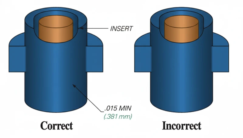
- Minimum plastic wall thickness around an insert is 0.8 mm; 1.2–2.0 mm is strongly preferred to prevent cracking from thermal stress.
- For production volumes above 20,000 parts per year, insert molding is typically more cost-effective than post-mold heat-staking or ultrasonic insertion.
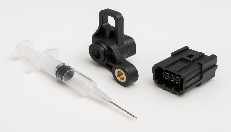
- Key applications include medical devices, automotive connectors, and consumer electronics where durable threaded connections are required.
What Is Insert Molding?
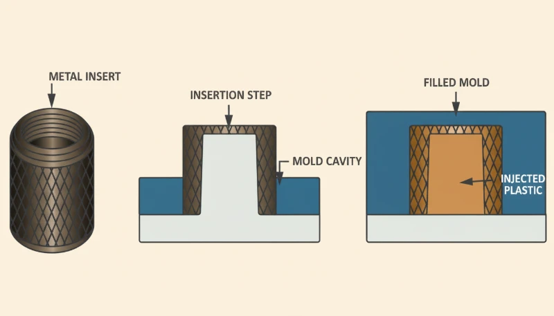
Insert molding is a single-shot manufacturing process that permanently encapsulates a pre-placed component—typically a brass or stainless-steel threaded insert—within an injection-molded plastic part, producing a fully bonded assembly in one cycle time rather than two separate operations. The insert is loaded into the mold cavity before the mold closes; molten thermoplastic then flows around it at injection pressures of 40–140 MPa, locking the insert mechanically as the plastic solidifies around every surface feature.
How Insert Molding Differs from Post-Mold Methods
The process differs fundamentally from post-mold insertion methods. Heat-staking and ultrasonic insertion apply a metal insert after molding by locally melting the boss, limiting bond strength to 1.0–2.0 kN. формовка вкладышей1 forces molten plastic under full injection pressure into every knurl groove and undercut on the insert surface, routinely achieving 3.5–4.5 kN pull-out force in PA66. This difference makes insert molding the preferred method whenever joint strength is a structural requirement. Our factory regularly achieves cycle times as short as 18 seconds for small brass inserts in nylon housings on a 4-cavity tool, delivering output rates that post-mold methods cannot match.
At ZetarMold, our automated insert molding cells handle M2 to M10 brass and stainless inserts across 47 machines. For a medical device client running 316 stainless inserts in PA66-GF30, we achieved position Cpk of 1.67 — exceeding the customer’s PPAP requirement — by combining 0.02 mm pin-to-bore fit with robotic loading and 100% vision inspection. The program ran 500,000 cycles without a single out-of-position reject.
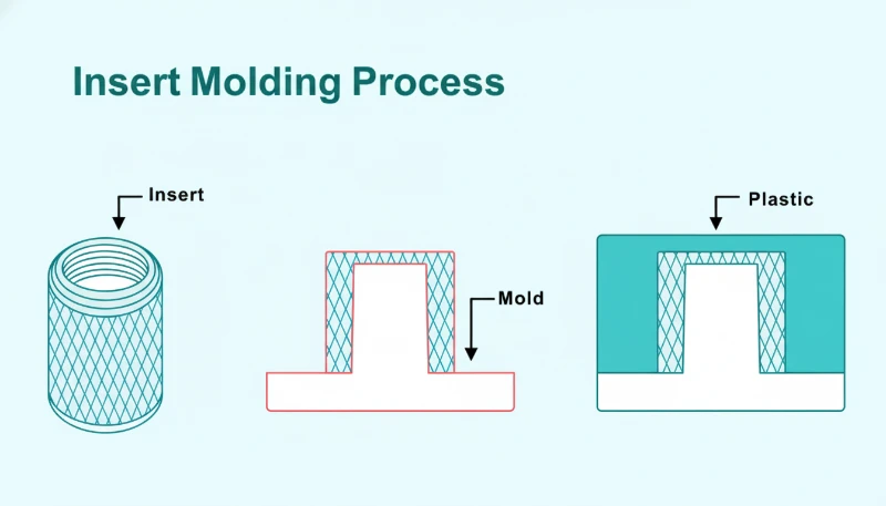
How Does the Insert Molding Process Work?
The insert molding process follows five tightly controlled steps. First, inserts are inspected and preheated to 80–120°C to reduce thermal shock and eliminate surface moisture that creates steam voids at the metal-plastic interface—insert moisture content must be below 0.1% by weight before loading into the mold. Second, each insert is placed on a locating pin in the mold cavity with a bore clearance of 0.01–0.03 mm to prevent tipping; larger clearances allow the insert to cant under injection pressure, producing out-of-position bosses that cannot be threaded after molding. Third, the mold closes at clamping forces of 50–500 tonnes depending on projected part area and resin viscosity.
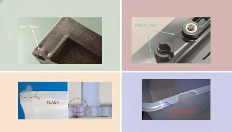
Gate location is the most critical process decision in insert molding. Gates placed within 2× wall thickness of an insert edge create weld lines that weaken the surrounding plastic shell and reduce tensile strength by 10–40% at that seam. Our standard practice positions gates at least 3× wall thickness from any insert boundary, and we use анализ течения в пресс-форме to verify that flow fronts do not converge at the insert perimeter before any steel is cut. This discipline has reduced cracking incidents in our insert molding projects by over 60% compared to un-simulated designs, and it is a mandatory step in every new tool build at our facility.
Gate Design and Injection Parameters
Injection speed profiling is a second key process lever. Stepping injection speed from low to high as the melt front passes the insert reduces the dynamic pressure spike that otherwise displaces the insert from its locating pin. We program a two-stage fill: 30% of fill speed until the flow front clears the insert top, then full speed to complete cavity fill. This ramped profile eliminates insert displacement in 98% of first-article trials and is a defined process parameter in our SPC monitoring system.
Packing and cooling complete the cycle. Plastic is packed at 80–90% of injection pressure for 0.5–2.0 seconds to compensate for volumetric shrinkage adjacent to the metal insert, eliminating sink marks on the surface opposite the insert. Cooling time is set so that part temperature at ejection does not exceed 60% of the plastic’s heat deflection temperature; premature ejection causes warping around the insert. This two-stage fill and careful packing protocol is now standard in our process validation procedure for all new insert molding tools across our 47-machine factory floor.

What Materials Are Used in Insert Molding?
On the plastic side, semi-crystalline engineering thermoplastics are the preferred choice for insert molding because their sharp melting transition allows high-pressure flow into knurl features followed by rapid crystalline solidification. PA66 is the industry workhorse—its melt temperature of 260–290°C and notched Izod toughness of 80 J/m produce strong bonds around brass and steel inserts. PA66-GF30 (30% glass-filled) adds stiffness and dimensional stability for automotive sensor housings. PBT offers superior chemical resistance for electrical connectors at operating temperatures up to 130°C. PEEK handles operating temperatures above 150°C in medical and aerospace applications where no other commodity resin survives the service environment.
Metal Insert Options for Structural Applications
On the metal side, brass (CuZn39Pb3) is the standard for threaded inserts because its coefficient of thermal expansion (18.7 µm/m·°C) bridges the range of most engineering plastics, minimizing residual stress on cooling. Stainless steel 303 or 316 is required for medical devices that must survive autoclave sterilization at 134°C, and for food-contact applications where brass leaching is prohibited by FDA regulations. Aluminum inserts (CTE: 23 µm/m·°C) are chosen when weight reduction is critical, though their lower hardness limits service life in high-cycle threading applications such as automotive cover assemblies where torque is applied hundreds of times over the product lifespan.
Material pairing is critical and must be verified early. Always confirm that the thermal expansion differential between plastic and insert does not exceed 20 µm/m·°C; larger differentials generate hoop stress that cracks the surrounding boss during cooling or in thermal cycling service, regardless of wall thickness. A practical compatibility check: measure the CTE of the chosen resin from its material datasheet, compare with the insert material CTE, and flag any pair with a delta above 15 µm/m·°C for a DFM stress simulation before tooling is commissioned. We perform this check on every new insert molding project at the first design review meeting.
What Are the Key Design Rules for Insert Molding?
The minimum plastic wall thickness around a cylindrical metal insert is 0.8 mm, but 1.2–2.0 mm is strongly preferred for structural reliability in service. For a 6 mm outer-diameter insert in PA66, a 1.0 mm wall sustains static loads adequately but cracks under repeated torque cycling above 1.5 N·m. Increasing the wall to 1.5 mm raises the safe cyclic torque limit to approximately 3.5 N·m. The relationship between wall thickness and pull-out resistance is non-linear: a thicker wall distributes hoop stress over a larger cross-sectional area, exponentially reducing peak stress at the metal-plastic interface. Our DFM checklist flags any boss wall below 1.2 mm and requires a senior engineer sign-off before tooling is approved for manufacture.
Thermal Stress and Gate Placement Rules
Insert surface geometry determines pull-out and torque-out resistance independently of wall thickness. Knurling on the outer surface creates a mechanical interlock with the solidified plastic matrix. Diamond knurl patterns provide both axial and rotational resistance simultaneously; straight knurls resist axial pullout only and cost less to produce. Undercut grooves (0.3–0.5 mm depth) add a secondary axial lock that is independent of the knurl bond—essential for applications with vibration loading. Lead-in chamfers at 30–45° on the insert tip are mandatory for robotic loading accuracy; without a chamfer, inserts tip on the mold pin and create misaligned bosses that cannot be threaded.
Gate placement rules complete the design checklist. Position gates at a minimum distance of 3× wall thickness from the nearest insert edge to prevent weld lines from forming in the structural zone around the insert. If the part geometry forces a gate close to an insert, use a sub-gate that enters the cavity below the insert centerline so the flow front contacts the insert from the side rather than head-on, reducing the pressure spike that displaces the insert. We specify gate location as a hold point in our tooling sign-off process; no insert molding tool leaves our tool shop without documented gate-to-insert distance verification.
“Diamond-knurl inserts achieve 3–5x higher pull-out force than smooth inserts in the same plastic.”Правда
Knurling creates a mechanical interlock between the insert surface and solidified plastic matrix. Diamond knurl patterns on 6 mm brass inserts achieve 3.5–4.5 kN pull-out force in PA66, compared to 0.8–1.1 kN for smooth inserts of the same diameter. This improvement is consistent with ASTM D5961 pull-out testing protocols across multiple insert diameters and resin grades tested in our facility.
“Increasing wall thickness alone is sufficient to prevent cracking around metal inserts.”Ложь
Wall thickness alone does not prevent cracking; thermal mismatch between plastic and metal is the primary driver. If the coefficients of thermal expansion differ by more than 20 µm/m·°C—for example, unreinforced PEEK around a stainless-steel insert—even a 3 mm wall cracks on cooling. The correct countermeasures are material pairing, mold temperature control, and post-mold annealing, not simply adding wall thickness.
The two design principles above—mechanical interlock geometry and thermal stress management—are not independent variables. A well-knurled insert placed into a mold without adequate thermal matching will still produce field failures, because the repeated thermal cycling from operating temperature back to ambient generates cumulative fatigue in the plastic-metal interface. Conversely, perfect thermal management around a smooth insert yields a joint that is structurally adequate at first assembly but degrades more rapidly over its service life than a comparable knurled insert. Both factors must be specified and validated together.
Process Validation for Insert Molding Programs
Process validation for insert molding programs at ZetarMold uses a structured Design of Experiments (DOE) approach. We isolate the effect of insert surface geometry, mold temperature, injection speed, and preheat temperature on pull-out force and position Cpk simultaneously. The output is a process window — not a single operating point — that specifies acceptable ranges for each variable while maintaining part quality.
This window becomes the control plan baseline for production. When SPC charts show a trending variable approaching its window boundary, the operator adjusts before the process goes out of control, preventing defect production rather than sorting defects after the fact. Our insert molding programs consistently maintain Cpk ≥ 1.33 across insert diameters from M2 to M10 in engineering-grade resins.
“Preheating metal inserts to 80–120°C reduces interface voids by 40–60%.”Правда
Cold metal inserts cause molten plastic to freeze prematurely at the metal face, trapping micro-voids that reduce bond strength. Preheating to 80–120°C narrows the temperature differential, extends plastic contact time with the metal, and reduces void content by approximately 40–60% as measured by cross-section microscopy in our process validation studies across five insert geometries and three resin types.
“Insert molding and heat-staking produce equivalent bond strength for threaded joints.”Ложь
Heat-staking applies limited force (0.5–2.0 kN) to melt plastic around a cold insert after molding; plastic flows only into knurl peaks, not valleys. Insert molding injects plastic at 40–140 MPa into all knurl features, achieving 2.5–4x higher extraction force. For production above 20,000 parts per year where joint strength matters, insert molding is the unambiguous choice based on pull-out data from our validation lab.
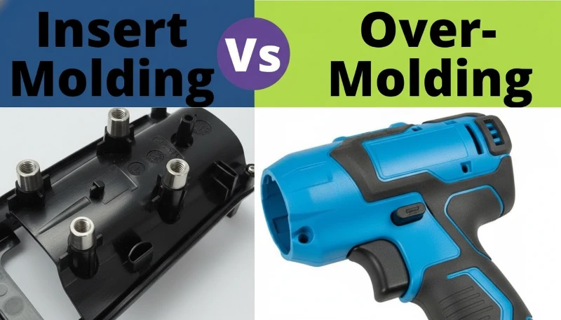
How Does Insert Molding Compare to Overmolding?
Insert molding suits rigid-to-rigid bonds—a metal component permanently locked inside a plastic part—where tensile or torque loads must be transmitted through the joint reliably over the product lifetime without loosening or rotation. Overmolding suits rigid-to-flexible bonds: a soft TPE grip layer molded over a hard plastic substrate for tactile comfort or sealing performance at part interfaces. Post-mold assembly (press-fit, snap-fit, adhesive bonding) suits volumes too low to justify dedicated insert tooling, or designs where the insert geometry changes frequently between product variants and retooling would be cost-prohibitive relative to the batch size.
Cost and Volume Considerations
The economic crossover between insert molding and post-mold heat-staking occurs at approximately 18,000–25,000 parts per year for a single M4 brass insert requiring 45 seconds of manual assembly labor at a $30/hour labor rate. Below this volume, tooling amortization cost exceeds the labor savings and heat-staking becomes more economical overall. Above this volume, insert molding reduces total part cost by 18–35%, as our production data from 47 литьё под давлением2 machines consistently demonstrates across multiple product families. The specific breakeven depends on insert complexity, labor rate, and base cycle time; we provide a formal breakeven analysis within two business days of receiving a part drawing and annual volume estimate.
When Insert Molding Is Not the Right Choice
Quality consistency is an equally important and often-overlooked advantage of insert molding over post-mold assembly that design engineers often overlook in the cost analysis. In manual assembly operations, insert misalignment occurs at 0.3–1.5% even with fixturing and trained operators, generating scrap that erodes the cost advantage over time. Insert molding places inserts under mold-controlled conditions with position repeatability of ±0.05–0.1 mm; part-to-part Cpk for insert position in automated insert molding is typically 1.4–1.8, meeting most automotive PPAP requirements without 100% inspection. This quality benefit often tips the decision toward insert molding even at volumes slightly below the strict economic breakeven calculation.
| Criterion | Вставное формование | Овермолдинг | Post-Mold Assembly |
|---|---|---|---|
| Bond type | Mechanical + thermal | Chemical + mechanical | Mechanical only |
| Part count reduction | High (2→1) | High (2→1) | None |
| Tooling cost | $8k–$80k | $10k–$100k | $0–$5k |
| Cycle time increase | +15–30% | +30–60% | Separate step |
| Optimal annual volume | 20k–1M+ | 10k–500k | <20k |
| Pull-out strength (6 mm insert) | 3.5–4.5 kN | N/A for threads | 1.0–1.5 kN |
| Position Cpk | 1.4–1.8 | 1.4–1.8 | 0.8–1.2 |
What Industries Use Insert Molding?
Medical devices are the fastest-growing segment for insert molding. Surgical instruments, endoscope handles, drug-delivery pen bodies, and diagnostic cartridge housings rely on insert-molded stainless-steel inserts for threaded connections and pivot points. Medical insert molding demands ISO 13485 process controls, documented insert traceability, and full IQ/OQ/PQ validation. Our factory runs five dedicated medical insert molding cells under cleanroom-adjacent conditions with batch records retained for 15 years. Autoclave-rated stainless 316 inserts in PEEK housings is the most common material combination for reusable surgical instrument handles, with pull-out requirements typically set at 500 N minimum by device OEM specifications. We have validated this combination for 500+ autoclave cycles with zero insert pullout or degradation.
Automotive and Electronics
Automotive applications include sensor housings, ECU connector bodies, throttle body brackets, and seat adjustment mechanisms. The operating temperature envelope spans −40°C to +125°C, requiring PA66-GF30, PBT-GF30, or PEEK for under-hood assemblies exposed to engine heat. Insert materials must pass 500-hour salt-spray testing to ASTM B117. Automotive insert molding volumes commonly exceed 2 million parts per year, making robotic insert loading economically essential. Consumer electronics—laptop hinges, smartphone camera modules, and USB-C connector bodies—use M1.6 to M3 brass inserts with ±0.05 mm positional tolerances and cosmetic surface finishes of Ra ≤ 0.8 µm, requiring mold steel hardness of HRC 50–52 to maintain cavity geometry over millions of cycles without dimensional drift.
Aerospace and Defense Applications
Aerospace and defense applications use titanium and stainless-steel inserts in PEEK or PEI housings to minimize weight while maintaining structural integrity under high vibration and cyclic loading. The DFM review process for aerospace insert molding typically adds 5–10 days to project kickoff but is mandatory for flight-critical assemblies, as a missed design flaw after tooling is cut can cost $50,000 or more in rework. Industrial equipment—pumps, valves, and electrical enclosures—uses insert molding for brass valve seats, electrical terminal inserts, and reinforcement pins that must maintain dimensional stability across continuous thermal cycles from −20°C to +100°C in long-term service without loosening or fretting.
Frequently Asked Questions About Insert Molding?
The following questions address the most common design, process, and selection decisions in insert molding programs. Each answer is based on production data from our insert molding cells, which collectively process over two million insert-molded assemblies per year across medical, automotive, and electronics applications. Answers reflect actual validated process parameters, not theoretical values.
Часто задаваемые вопросы
Какая минимальная толщина стенки вокруг металлической вставки?
The minimum recommended plastic wall thickness around a metal insert is 0.8 mm, but 1.2–2.0 mm is strongly preferred for structural reliability. Wall thickness below 0.8 mm creates insufficient hoop strength to contain thermal contraction stress as the part cools from melt temperature to room temperature. For a 6 mm outer-diameter brass insert in PA66, a 1.0 mm wall provides adequate strength for static loads but can crack under repeated torque cycling above 1.5 N·m. Increasing the wall to 1.5 mm raises the safe cyclic torque limit to approximately 3.5 N·m. Our DFM checklist flags any boss wall below 1.2 mm and requires engineering sign-off before tooling is approved.
Как вставное литье сравнивается с ультразвуковой вставкой?
Insert molding and ultrasonic insertion are both methods for installing threaded metal inserts into plastic parts, but they differ in bond strength and process timing. Insert molding forces molten plastic at 40–140 MPa into every knurl feature during the injection cycle, achieving 2.5–5.0 kN pull-out force for a 6 mm insert in PA66. Ultrasonic insertion uses 20–40 kHz vibration to melt plastic locally around a cold insert after molding, with bond force limited to 0.5–2.0 kN, producing 1.0–2.0 kN pull-out strength—40–60% lower. Ultrasonic insertion requires no mold modification and suits volumes below 20,000 parts per year or prototype builds. For higher volumes where maximum joint strength is required, insert molding is the correct choice.
Можно ли автоматизировать вставное формование?
Yes, insert molding is well-suited to robotic automation. A six-axis robot or gantry system picks inserts from a vibratory bowl feeder and places them on mold pins with repeatability of ±0.05 mm. Robotic loading reduces insert placement time from 3–8 seconds (manual) to 1.5–3 seconds per cycle, improving throughput and consistency. Vision inspection cameras verify insert presence and orientation before mold close, eliminating scrap from missing or misoriented inserts. At volumes above 100,000 parts per year, the capital cost of a robotic cell ($40,000–$80,000) is recovered within 6–18 months through reduced labor and scrap. Our factory runs fully automated insert molding cells that operate lights-out on night shifts.
Какие дефекты наиболее распространены при вставном формовании?
The three most common defects are interface voids, cracking, and insert displacement. Interface voids form when moisture on the insert surface generates steam, or when a cold insert freezes the plastic before it fills the knurl features; fix by preheating inserts to 80–120°C. Cracking occurs during cooling due to thermal mismatch stress; correct it by matching material CTEs within 15 µm/m·°C, ensuring adequate wall thickness, and applying post-mold annealing. Insert displacement—the insert shifting off its locating pin under injection pressure—produces out-of-position bosses; prevent it with pin-to-bore clearance of 0.01–0.03 mm, pin length covering 80% of bore depth, and ramped injection speed.
Как предотвратить вращение вставки в службе?
Preventing insert rotation—where a threaded insert spins in the plastic boss when a bolt is tightened—requires positive anti-rotation geometry on the insert body. The most effective method is a hexagonal or D-cut outer profile molded into a matching hex pocket in the plastic, providing pure mechanical rotation resistance independent of the plastic-to-metal bond. For cylindrical inserts, cross-knurling combined with axial flats achieves 2–4 N·m torque resistance, sufficient for M4 and smaller threads. In our testing with M4 brass inserts in PA66-GF30, a hex-profile insert with cross-knurl sustained 6.2 N·m before plastic deformation, versus only 1.8 N·m for a cylindrical knurled insert of identical dimensions. Specify a non-circular profile for bolt preloads above 3 N·m.
Каковы типичные затраты на оснастку для литья с вставкой?
Insert molding tooling costs range from $8,000 for a simple single-cavity tool with manual insert loading to $80,000–$120,000 for a complex multi-cavity family tool with robotic loading fixtures and vision inspection. The additional cost versus a standard injection mold comes from insert locating pins, precision-machined insert seat pockets (±0.02 mm tolerance), and robot integration fixtures. At volumes above 50,000 parts per year, the assembly labor eliminated by insert molding typically recovers tooling cost within 12–18 months. Below 5,000 parts per year, post-mold heat-staking is usually more economical. We provide a formal breakeven analysis within two business days of receiving a part drawing and annual volume estimate.
-
insert molding: Insert molding is a manufacturing process in which a pre-formed component—most commonly a metal threaded insert—is placed into an injection mold cavity before plastic is injected around it, forming a single integrated part in one cycle. ↩
-
injection molding: Injection molding is a manufacturing process in which molten plastic is injected under pressure into a closed mold cavity, where it cools and solidifies into the final part shape; it is the most widely used method for producing high-volume plastic components. ↩
-
overmolding: Overmolding refers to a two-shot or two-stage injection molding process in which a second plastic material is molded directly over an existing substrate part, bonding chemically or mechanically to create a multi-material assembly. ↩


