 Przejdź do treści

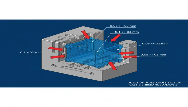
– 3D printing and injection molding are increasingly used together, with 3D-printed molds and inserts cutting tooling lead times from weeks to days.
– Hybrid manufacturing combines the design freedom of 3D printing with the high-volume efficiency of injection molding.
– Printed tooling works best for prototype runs under 500 shots, while steel molds remain essential for production volumes above 10,000 parts.
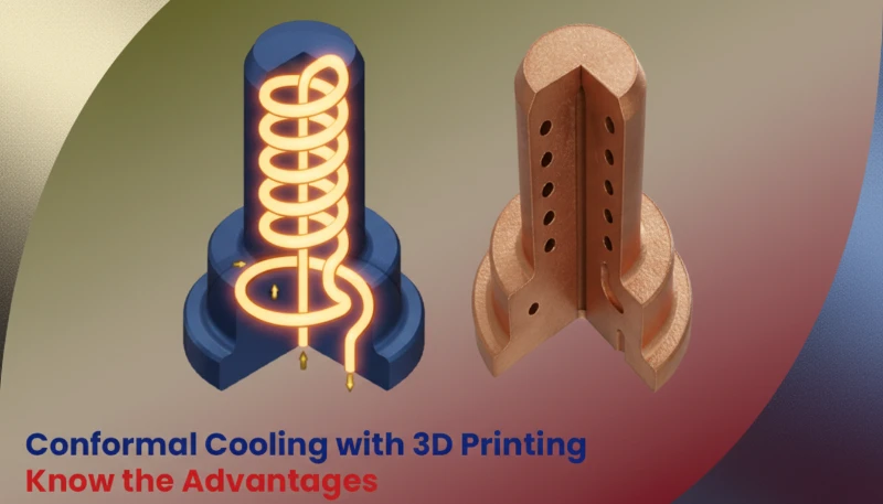
– Conformal cooling channels—impossible with traditional machining—can be integrated into 3D-printed mold inserts to reduce cycle times by 20–40%.
– The convergence of both technologies is reshaping product development timelines, helping our customers go from CAD to first-article part in as little as 72 hours.
What Does the Integration of 3D Printing and Injection Molding Actually Mean?
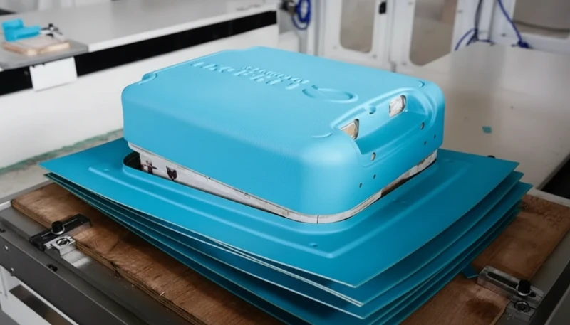
The integration of 3D printing and injection molding means using additive manufacturing at one or more stages of the injection molding workflow—whether for rapid tooling, conformal cooling inserts, bridge tooling, or end-use part production—to accelerate development and reduce cost. In our factory, we’ve been testing and deploying this hybrid approach since 2022, and the results have changed how we think about product development timelines entirely.

Traditional injection molding tooling requires precision CNC machining of hardened steel or aluminum—a process that can take 4–8 weeks and cost $5,000–$80,000 depending on part complexity. 3D printing disrupts this bottleneck at two critical points: rapid tooling (printing the mold or insert directly) and rapid prototyping (printing parts to validate design before committing to steel). Here’s how those two paths diverge:
| Approach | Use Case | Czas realizacji | Shot Life | Cost Range |
|---|---|---|---|---|
| 3D-Printed Mold (Resin/PA) | Prototyping, 50–500 shots | 1–3 days | 50–500 | $200–$2,000 |
| Metal-Filled 3D-Printed Insert | Bridge tooling, 500–5,000 shots | 3–7 days | 500–5,000 | $1,000–$8,000 |
| Aluminum CNC Mold | Low-volume production | 2–3 weeks | 10,000–50,000 | $3,000–$15,000 |
| Hardened Steel Mold | Produkcja na dużą skalę | 4–8 weeks | 500,000+ | $10,000–$100,000 |
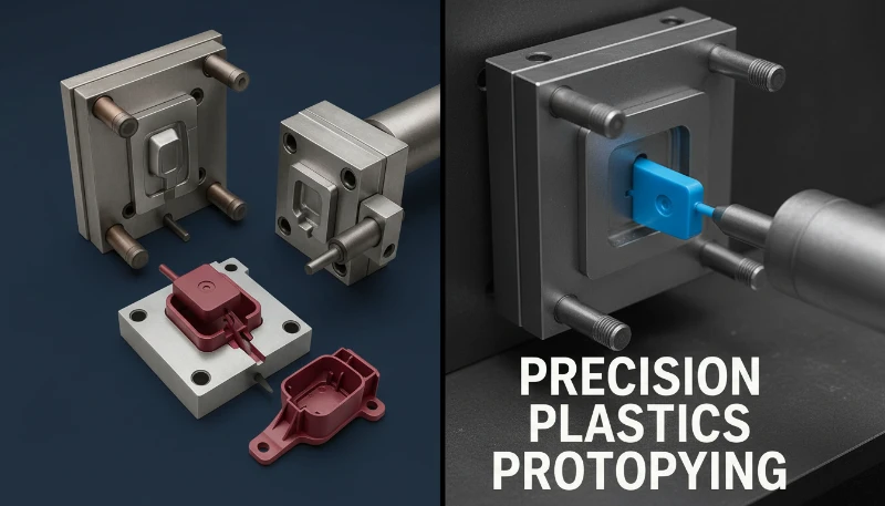
How Are 3D-Printed Molds Used in Injection Molding Today?
3D-printed molds are used in injection molding primarily for prototype validation, design iteration, and bridge production. They are printed using high-temperature resins (such as Formlabs High Temp Resin or Henkel Loctite IND405) or filled nylons capable of surviving the thermal and pressure stresses of a typical injection cycle. In our facility, we’ve run PP and ABS through printed resin inserts mounted in aluminum mold frames—achieving 50–150 good parts before the insert showed signs of wear at the gate area.
The key limitation is thermal conductivity1. Polymer-based printed tooling dissipates heat roughly 100–200× slower than steel (0.2–0.4 W/m·K vs. 28–50 W/m·K). This forces longer cycle times—often 2–4× longer than a production steel tool—and limits the barrel temperature you can use. For materials like PC or nylon that require melt temperatures above 280°C, printed resin tools typically fail within 10–30 shots. The practical material window for printed tooling is PP, HDPE, LDPE, and soft TPEs.
“3D-printed molds can handle any plastic that injection molding machines use.”Fałsz
Most 3D-printed polymer molds are limited to low-temperature materials like PP, HDPE, and soft TPEs (melt temps below ~260°C). High-engineering resins like PC (280–320°C) or PEEK (370–400°C) destroy printed mold inserts within a few shots due to thermal degradation.
“3D-printed mold inserts are excellent for running 50–300 prototype shots in PP or ABS.”Prawda
High-temp resins and SLS nylon inserts mounted in aluminum frames can reliably produce 50–500 parts in PP, ABS, and soft TPEs at normal injection speeds. This approach reduces prototype tooling lead time from weeks to 1–3 days and cuts cost by 70–90% versus CNC aluminum tools.
What is Conformal Cooling and How Does 3D Printing Enable It?
Conformal cooling refers to cooling channels that follow the contour of the mold cavity surface at a uniform distance, rather than running in straight lines drilled through the mold block. 3D printing—specifically metal additive manufacturing (DMLS, SLM, or binder jetting)—is the only cost-effective way to create these complex internal geometries. In conventional CNC machining, curved internal channels are essentially impossible without gun-drilling straight lines and plugging intersections.
The performance gains are significant. A 2024 study published in the Journal of Manufacturing Processes found that conformal cooling reduced average part temperature by 18–34°C at ejection, shortened cooling time by 25–45%, and reduced warpage by up to 60% on asymmetric parts compared to conventional straight-line channels. In our factory, we implemented conformal cooling in a complex automotive bracket mold using a DMLS H13 insert, and cycle time dropped from 42 seconds to 26 seconds—a 38% reduction that added up to roughly 280,000 additional parts per year on a two-cavity tool.
| Metryczny | Conventional Cooling | Conformal Cooling (3D-Printed) | Improvement |
|---|---|---|---|
| Czas chłodzenia | 18–25 sec | 10–15 sec | 30–45% faster |
| Part Warpage | 0.3–0.8 mm | 0.1–0.3 mm | Części formowane wtryskowo z PEEK dla zastosowań motoryzacyjnych i lotniczych |
| Ejection Temperature | 85–110°C | 55–75°C | 20–35°C lower |
| Cycle Time Savings | Baseline | –20 to –40% | Significant |
What Role Does 3D Printing Play in Bridge Tooling?
Bridge tooling means producing parts in final or near-final material while the production steel tool is being machined. 3D printing enables bridge tooling either directly (printing a polymer or metal mold insert) or indirectly (printing a pattern for casting urethane or epoxy molds). This approach lets customers begin low-volume manufacturing—typically 500–5,000 parts—without waiting 4–8 weeks for a production tool. We use bridge tooling regularly for clients who need to supply initial inventory or run market validation while the production mold is in progress.
“Bridge tooling always produces parts that are different in quality from production parts.”Fałsz
Bridge tools using metal-filled 3D-printed inserts or aluminum CNC molds can produce parts in the same material, at the same injection pressure and temperature as production. The parts are functionally identical—only the mold’s shot life and cycle efficiency differ.
“Bridge tooling using 3D-printed inserts can cut pre-production lead time by 60–80% versus waiting for a production steel mold.”Prawda
A production steel mold for a complex part might take 6–10 weeks. A bridge tool using metal-filled 3D-printed or CNC aluminum inserts can be ready in 1–2 weeks, giving manufacturers access to real injection-molded parts while the production tool is in fabrication.
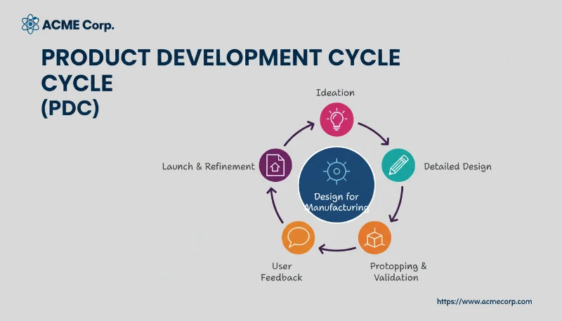
How Does 3D Printing Reduce Injection Molding Development Time?
3D printing reduces injection molding development time primarily by compressing the design iteration loop. Traditionally, going from CAD to a molded part required 4–8 weeks of tooling plus 1–2 weeks of first-article inspection and revision—sometimes repeated two or three times. With 3D-printed tooling, each iteration takes 1–5 days. In our experience, clients who adopt a hybrid approach typically reach final design approval 40–60% faster than those relying exclusively on CNC tooling for validation.
The biggest time savings come at two stages: (1) gate and runner optimization—changes that would require re-machining a steel tool in 1–2 weeks can be incorporated in a new printed insert overnight; and (2) parting line and draft angle validation—engineers can run actual molded parts with different draft configurations, catching issues that simulation alone might miss. We’ve seen cases where a single design iteration caught a warpage issue that Analiza przepływu formy2 had underestimated, avoiding a very expensive steel tool modification.
What Are the Limitations of 3D-Printed Tooling for Injection Molding?
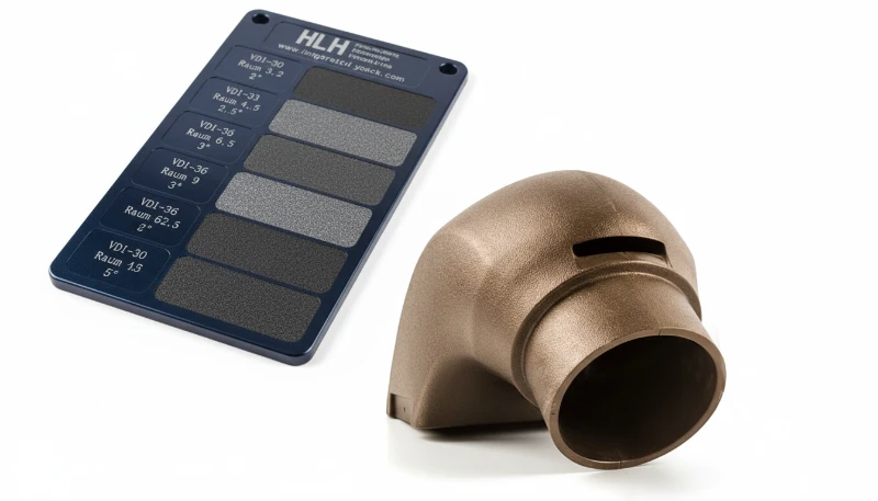
The primary limitations of 3D-printed tooling for injection molding are shot life, surface finish, and material compatibility. Polymer-printed molds typically survive 50–500 shots before gate erosion or surface degradation becomes unacceptable. Metal-printed inserts (DMLS or SLM in tool steel or Inconel) can reach 10,000–50,000 shots but at a cost of $5,000–$25,000 per insert—rivaling some aluminum CNC tools. Surface finish from SLS or FDM prints requires post-processing (sanding, polishing) to achieve the SPI A-3 or better finish3 finishes that many parts demand.
What Are the Real-World Applications Where Both Technologies Work Together?
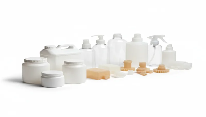
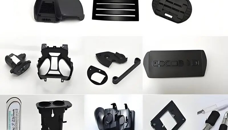
The most successful real-world applications of 3D printing and injection molding integration include: (1) Consumer electronics housings—where frequent model updates make flexible tooling economically essential; (2) Medical devices—where regulatory pathways require testing with actual molded parts in production material before steel tool investment; (3) Automotive interior components—where conformal cooling in 3D-printed metal inserts reduces cycle time on high-complexity visible parts; and (4) Industrial equipment housings—where low annual volumes (1,000–10,000 parts) make a bridge tool the permanent tooling solution.
FAQ
Can you injection mold with a 3D-printed mold?
Yes. High-temperature resin or SLS nylon molds printed using photopolymer or powder-bed fusion processes can function as injection mold inserts for prototype runs of 50–500 parts in low-temperature materials (PP, HDPE, TPE). They must be mounted in rigid aluminum frames to handle injection pressures of 500–1,200 bar.
What materials can be used in 3D-printed injection molds?
Low-melt-point materials work best: PP (melt temp 200–250°C), HDPE (180–240°C), LDPE (160–220°C), and soft TPEs (150–220°C). Engineering resins like PC (280–320°C), PA66 (260–290°C), and POM (190–230°C with high flash risk) tend to degrade printed polymer tooling rapidly.
How long does a 3D-printed mold last?
It depends on the printing material and the molded resin. High-temp resin molds: 50–200 shots. SLS nylon molds: 100–500 shots. Metal-filled polymer composites: 200–1,000 shots. Metal 3D-printed inserts (DMLS tool steel): 10,000–50,000 shots.
Is conformal cooling expensive to implement?
Metal additive manufacturing for a conformal cooling insert typically costs $3,000–$20,000 depending on insert size and complexity. However, the ROI is strong on production tools: a 25–40% cycle time reduction on a high-volume part can recover the insert cost in weeks. For prototype tools, conformal cooling is not cost-effective.
Will 3D printing eventually replace injection molding?
For low volumes (under 100 parts) and complex geometries, 3D printing is already the preferred choice. But for volumes above 10,000 parts, injection molding’s per-unit cost advantage (often 10–100× cheaper per part) and superior surface finish make it irreplaceable. The future is hybrid: 3D printing for tooling acceleration and design validation, injection molding for production.
What is the difference between direct and indirect 3D-printed tooling?
Direct tooling means 3D printing the mold cavity insert itself. Indirect tooling means printing a pattern that is used to cast a urethane, epoxy, or aluminum mold—useful when the printed material itself cannot survive molding conditions but can serve as a casting master.
Podsumowanie
3D printing and injection molding are not competing technologies—they are increasingly complementary tools in a smart manufacturing strategy. 3D printing accelerates the development phase: prototype tooling reduces iteration cycles from weeks to days, conformal cooling unlocks cycle time improvements impossible with conventional machining, and bridge tooling fills the gap between design approval and full-scale production. Injection molding remains the gold standard for production volumes above 10,000 parts, delivering surface quality, material selection, and per-unit economics that additive manufacturing cannot match at scale. In our factory, the integration of both approaches has reduced average development lead times by 45% and tooling-related design change costs by over 60%—a transformation we expect to deepen as metal additive manufacturing costs continue to fall.
-
Thermal conductivity is the measure of a material’s ability to transfer heat, expressed in W/m·K. Tool steel has thermal conductivity of 28–50 W/m·K, while polymer-based 3D-printed materials typically range from 0.2–0.4 W/m·K—roughly 100–200× lower—which directly limits cooling performance in printed mold inserts. ↩
-
Mold flow analysis (also called injection molding simulation) uses computational fluid dynamics to predict how molten plastic will fill, pack, and cool inside a mold cavity. Tools like Moldflow and Moldex3D can identify potential defects—weld lines, air traps, warpage—before the mold is built. ↩
-
SPI surface finish standards (defined by the Society of the Plastics Industry) grade mold cavity finishes from A-1 (mirror polish, Ra 0.012–0.025 μm) to D-3 (rough EDM, Ra 3.2–12.5 μm). Most consumer-facing plastic parts require A-2 or A-3 finish (Ra 0.025–0.1 μm), which requires careful hand polishing of printed metal inserts. ↩


