 Skip to content

micro injection molding1 is used when a plastic part is too small, too thin, or too tolerance-sensitive for ordinary production assumptions. The process still follows the same basic injection molding principle, but the risk profile changes because a tiny gate, a few microns of steel variation, a 0.01g shot-size change, a ±0.001 inch tolerance target, or a short material residence-time error can decide whether the part fills correctly.
For engineers, the practical question is not only whether a supplier owns a small press. The better question is whether the supplier can connect micro mold design, material drying, gate size, venting, inspection method, and repeatable process control into one documented workflow. Without that workflow, a prototype may look acceptable while production yield remains unstable.
This guide explains where micro injection molding fits, which design and material choices matter most, and how injection molding sourcing teams should compare suppliers before requesting a quote. It is written for buyers who need small precision parts for medical, electronics, connector, sensor, consumer, or industrial assemblies.
- Micro injection molding is best for very small plastic parts, thin walls, micro features, and tight dimensional windows.
- The highest risks are gate design, venting, material residence time, thermal damage, and inspection capability.
- A supplier should prove mold-making precision, process control, and measurement method before promising volume production.
- Design teams should simplify undercuts, protect fragile pins, avoid unnecessary wall-thickness jumps, and define critical dimensions early.
- A good RFQ should include drawings, resin grade, tolerance targets, annual volume, cosmetic limits, inspection plan, and packaging requirements.
What is micro injection molding?
Micro injection molding is defined by the function, constraints, and tradeoffs explained in this section. Micro injection molding is a specialized precision molding process for parts that weigh less than 1 gram, have wall sections under 0.5 mm, or carry micro-scale features that standard molding cannot reliably produce. Every element — mold steel, screw design, gate size, venting, and inspection — must be built around small shot volumes and narrow process windows.
In ordinary injection molding, a small variation in temperature, pressure, or hold time may still produce usable parts. In micro molding, the same variation can cause short shots, flash, gate vestige2 problems, degraded resin, broken core pins, or parts that pass visual inspection but fail assembly. That is why the project should begin with a design-for-manufacturing review rather than a simple price request.
“Micro molded parts need earlier DFM review than many standard molded parts.”True
Small gates, thin walls, fragile pins, and limited inspection access reduce the margin for late changes. A supplier should review part geometry, resin behavior, gate options, ejection, venting, and measurement strategy before quoting production assumptions.
“Any supplier with a small injection molding machine can run micro injection molding.”False
Machine size is only one requirement. Micro molding also needs high-precision mold manufacturing, stable shot control, suitable screw and nozzle design, careful material handling, controlled ejection, and a measurement plan that can verify micro-scale dimensions.
When should engineers use micro injection molding?
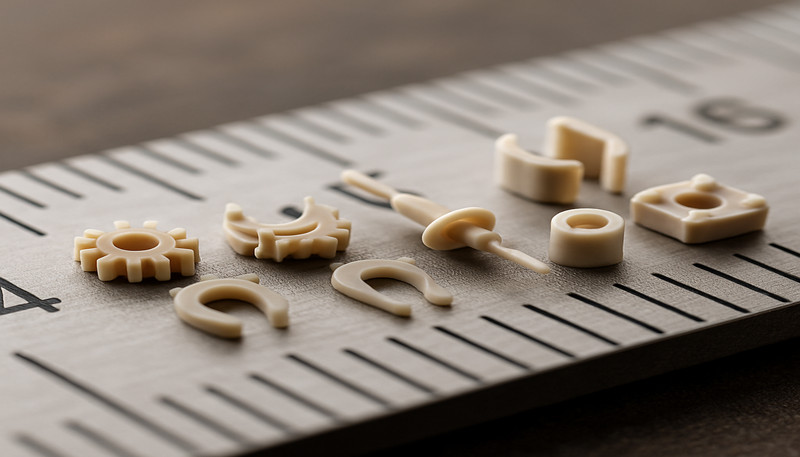
Micro injection molding is the right choice for tiny parts that need tighter process control than standard molding. Typical examples include miniature connectors, medical components, micro gears, sensor housings, small optical parts, precision clips, tiny fluid-control components, and thin-wall features that need repeatability across many cycles.
The strongest use cases have three conditions. First, the part geometry is stable enough to justify tooling. Second, the annual volume is high enough that molded repeatability matters more than one-off prototype flexibility. Third, the buyer can define which dimensions, surfaces, and functional features are truly critical. If these conditions are missing, CNC, 3D printing, or a simplified prototype mold may be a better first step.
Micro molding also becomes valuable when assembly cost is higher than molding cost. Combining features into one molded part can reduce manual assembly steps, but only if the mold can release the part safely and the process can keep dimensions stable across a full production run. Teams should compare the savings from part integration against the tooling risk created by tiny ribs, shutoffs, through-holes, and undercuts. In many cases, a well-designed micro mold reduces total part count and lowers per-unit assembly labor enough to justify the higher initial tooling investment.

Which design rules matter most for micro molded parts?
The most important design rule is to protect the process window. Keep wall thickness as consistent as the function allows — we typically recommend wall thickness variation under 15% for micro parts, compared to the 25% tolerance common in standard molding. Avoid sudden steel-safe changes near tiny features, and define where the gate can leave a visible or functional mark. Gate vestige that looks small on a normal part can become unacceptable on a micro part because the gate may sit near a sealing, sliding, or electrical-contact surface.
In practice, a gate mark larger than 0.1 mm on a 2 mm micro connector can interfere with mating, so gate type and location need explicit agreement between designer and mold maker before steel is cut.
Draft angle, parting line, and ejection are equally important. Micro parts are often difficult to grip, orient, and remove, so a weak ejection concept can damage parts faster than the molding process itself. For parts under 5 mm in any dimension, we recommend at least 0.5° draft per side — more if the surface has texture or micro features. If the design needs thin pins (under 1 mm diameter), narrow slots, or sharp internal corners, the mold maker must confirm whether those features can be machined, polished, vented, inspected, and maintained over the expected mold life. Core pins smaller than 0.3 mm diameter typically last fewer than 50,000 cycles before requiring replacement.
A practical engineering review should connect the part drawing to the mold concept. Use an injection mold design review to confirm gate location, runner balance, cooling path, steel access, venting, parting-line tolerance, and how the first samples will be measured. This review should happen before the buyer compares price because it changes both tooling cost and production risk.

“A micro molded part can fail because the inspection plan is weaker than the mold design.”True
If the supplier cannot measure the critical feature repeatably, the team cannot prove whether process changes improved the part. Micro projects need clear inspection fixtures, magnification method, dimensional report format, and sampling frequency.
“A smaller part always means a lower molding risk.”False
Smaller parts may use less resin, but they often require tighter tooling precision, more careful material control, and more difficult inspection. A low material cost does not remove the risk created by micro gates, thin walls, and fragile steel features.
How do materials and process windows change at micro scale?
Materials behave differently when shot size is very small. Resin can stay in the barrel too long, shear heat can rise quickly through a small gate, and a tiny moisture or drying error may create defects that are difficult to see until assembly. For engineering plastics such as PEEK (drying at 150°C for 3–4 hours, melt temperature 370–400°C), LCP (280–330°C melt), PC (120°C drying, 280–320°C melt), PA (80°C drying, 240–280°C melt), POM, PPS, and bio-compatible grades, the supplier should explain drying conditions, residence time limits (typically under 5 minutes for micro shots to avoid thermal degradation), melt-temperature limits, and whether the selected resin can fill the thinnest section without damage.
In our Shanghai factory, our 20+ years of injection molding and tooling experience, 47 injection molding machines from 90T to 1850T, 400+ plastic materials, and ISO 90013, ISO 13485, ISO 14001, and ISO 45001 systems help our engineers compare micro-part resin behavior, tooling risk, and inspection requirements before quoting.
For micro molding, material review should focus on resin residence time, drying records, viscosity stability, gate shear, and how the supplier proves dimensional repeatability with first-article data. This is why precision component examples are more useful than generic pellet photos when judging whether a supplier understands micro-scale production risk.
Process window documentation is especially important for micro molding because the visible difference between a good part and a defective one can be hard to detect without magnification. We recommend that production teams record initial parameter windows during T1 sampling, then narrow those windows based on SPC data from the first 500 to 1000 production shots. Key variables to track include peak injection pressure, screw position at switchover, cushion length, cycle time, and part weight — which for micro parts often needs a precision balance reading to 0.0001g.

How should buyers compare micro injection molding suppliers?
Supplier Evidence Checklist
A strong micro molding supplier comparison is an evidence-based RFQ review. Use the same drawings, resin grade, critical dimensions, target annual volume, cosmetic standards, regulatory expectations, packaging method, and current prototype issues. A supplier who only quotes from a screenshot cannot reliably evaluate micro tooling risk. Before sharing the RFQ, confirm that the supplier has experience with the specific resin family and the tolerance range your project requires. Many suppliers claim micro capability, but fewer can show documented process data from similar part geometries and material classes.
Ask each supplier to explain the mold concept, gate strategy, venting plan, inspection method, and expected process-control data. If the program has medical, electronic, or safety-related use, ask how the supplier records material lot, parameter changes, dimensional reports, and nonconforming parts. This does not need to be complicated, but it must be documented. A written process-control plan is one of the clearest signals that a supplier takes micro molding seriously, because it shows the team has thought through what can go wrong and how to catch it.
Before sharing your RFQ, confirm the supplier can answer these practical questions: What is the smallest feature they have successfully molded in production? How do they verify dimensions on parts under 5 mm? What is their typical mold life for core pins under 0.5 mm diameter? Can they share a sample dimensional report from a similar micro project? How do they handle steel corrections after T1 sampling?
Measurement And Sampling Proof
What separates a strong micro molding quote from a weak one?
For micro parts, the quote review should also confirm measurement method, fixture concept, resin traceability, and packaging protection. Teams should review the supplier’s basic injection molding capabilities alongside micro-specific skills, because a supplier that cannot control standard process variables reliably will struggle even more at micro scale.
A supplier comparison should also include how the team handles feedback after first samples. Micro parts often need small steel changes, adjusted gate vestige limits, revised inspection fixtures, or a tighter process window after T1. The strongest suppliers explain this correction path before the tool is built, because the real cost of a micro project is often hidden in repeated sampling loops, unclear measurement standards, and late design changes. When a supplier proactively identifies these risks during quoting, it shows that the team has practical experience producing similar micro parts and understands the difference between quoting a standard mold and managing a micro-scale project through sampling into stable production.
The best micro molding quote explains risk, not only price. It should identify tooling assumptions, measurement limits, resin risks, sampling plan, and production controls so buyers can avoid choosing a low price that later requires repeated tool changes. For broader process context, compare these assumptions with our injection molding complete guide before approving supplier commitments.
Need a quote for a micro injection molding project? Send ZetarMold your drawing, resin requirement, target volume, and critical dimensions. Our engineering team can review DFM risk, tooling assumptions, production molding options, and inspection planning before you commit to a mold build. We will respond with an engineering-focused assessment covering mold concept, gate strategy, venting plan, measurement method, and process stability for your product, not just a price. Request a free quote through ZetarMold, or benchmark your current supplier plan against an integrated mold manufacturing and production molding workflow with documented product quality controls.
Frequently Asked Questions About Micro Injection Molding?
Frequently Asked Questions
What is the main difference between micro injection molding and standard injection molding?
The main difference is the process window. Standard injection molding can often tolerate small variations in material, temperature, pressure, and handling. Micro injection molding has much less room for variation because the part, gate, wall section, and critical features are very small. The supplier must control mold precision, material residence time, venting, gate quality, ejection, and inspection method with more discipline. A micro project should therefore start with DFM and measurement planning, not only a machine-size discussion. Buyers should ask for evidence from tooling, molding, and inspection, not only a press list.
Which materials are common in micro injection molding?
Common materials include engineering thermoplastics such as PEEK, LCP, PC, PA, POM, PPS, PMMA, PP, and selected medical or bio-compatible grades. The right choice depends on strength, temperature resistance, dimensional stability, chemical exposure, sterilization method, and whether the part has thin walls or micro channels. Material drying and residence time are especially important because a small shot can be damaged by moisture, overheating, or excessive shear before the defect is obvious to the eye. The supplier should confirm processing limits before final resin approval.
How tight can micro injection molding tolerances be?
Tolerance depends on material, part geometry, mold steel condition, measurement method, and production volume. Some micro features may target very tight dimensions, but the supplier must prove that the tolerance can be machined, molded, measured, and repeated. Buyers should avoid asking for tight tolerances everywhere. A better approach is to mark truly critical dimensions, define functional gauges or inspection methods, and let the supplier explain which tolerances are realistic for stable production. The quote should separate critical tolerances from noncritical reference dimensions.
What should be included in a micro injection molding RFQ?
A strong RFQ should include 3D CAD, 2D drawings, resin grade, expected annual volume, target mold life, critical dimensions, cosmetic requirements, assembly requirements, packaging method, and any current prototype or failure information. If the part is used in medical, electronic, or safety-related applications, include inspection expectations and documentation requirements. The supplier should respond with mold concept, gate strategy, risk notes, lead time, sampling plan, and assumptions behind the quote. This makes supplier answers comparable and prevents hidden scope gaps during sourcing.
How do I choose a supplier for micro injection molding?
Choose a supplier by evidence, not by price alone. Ask whether the team can review DFM, build precision molds, control small shot sizes, handle the selected material, inspect micro-scale features, and document production changes. Review sample reports, measurement capability, tooling feedback speed, and how the supplier handles corrective actions after first samples. If a supplier cannot explain gate, venting, ejection, and inspection risks clearly, the quote may not reflect the real production challenge. A better supplier will identify tradeoffs before asking for a purchase order.
-
micro injection molding: Micro injection molding is a precision injection molding method used to manufacture very small plastic parts or parts with micro-scale features. ↩
-
gate vestige: Gate vestige is a visible mark or residue left on a molded plastic part at the location where the injection gate was removed after the molding cycle. ↩
-
ISO 9001: ISO 9001 is an international quality-management standard that describes how organizations control documented processes and continuous improvement. ↩


