 콘텐츠로 건너뛰기

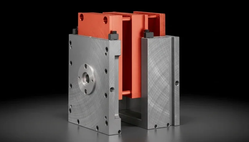
정밀 금형 작업을 위한 당사의 CNC 가공 접근법은 몇 가지 핵심 실무를 활용합니다.
– Properly accounting for material shrinkage during mold design is the single most important factor in achieving tight dimensional tolerance4s on molded parts.
– CNC machining tolerances of ±0.005 mm and EDM tolerances of ±0.003 mm are achievable in modern mold shops—but only when machines are thermally stable and calibrated regularly.
– Process consistency (holding pressure repeatability within ±2 bar, mold temperature within ±2°C) is as critical to dimensional accuracy as physical mold tolerances.
Why Does Mold Precision Matter More Than Machine Precision?
Mold precision matters more than machine precision because the mold defines part geometry—even a perfect injection machine cannot compensate for a poorly designed or imprecisely machined mold. In our factory, we’ve received molds from customers who paid for expensive machines but neglected mold quality, and the results are always the same: dimensional variation that cannot be corrected by process adjustment alone.
Injection molding part dimensional accuracy depends on three factors working together: mold dimensional accuracy (the physical cavity dimensions), material properties (specifically shrinkage compensation1 and anisotropy), and process consistency (injection pressure, melt temperature, and cooling time repeatability). Remove any one of these three, and dimensional control degrades.
The industry benchmark for precision injection molding is achieving tolerances conforming to DIN 16901 or ISO 20457 dimensional tolerance standards. For example, ISO 20457 Class M1 (highest precision) requires tolerances of ±0.05 mm on dimensions up to 50 mm. Achieving this level demands not just tight machining tolerances—it requires validated shrinkage factors, balanced cooling, and a statistically controlled production process (Cpk ≥ 1.67).
How Does Accurate Shrinkage Compensation Improve Dimensional Precision?
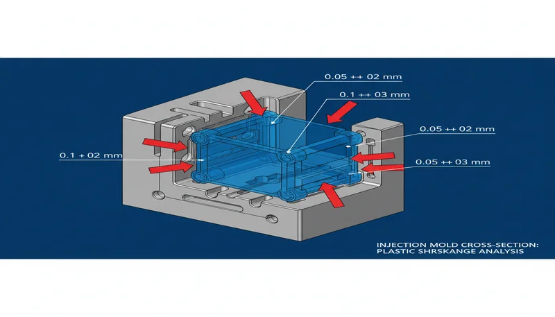
Accurate shrinkage compensation improves dimensional precision by sizing the mold cavity to produce parts at the correct final dimension after the plastic cools and contracts. Every thermoplastic material shrinks volumetrically as it transitions from melt to solid, and the mold must be designed larger than the desired part by exactly the right amount to compensate. In our operation, shrinkage compensation is the first and most critical mold design decision for any precision application.
Nominal shrinkage rates are published by resin manufacturers—typically 0.4–0.7% for ABS, 1.0–2.5% for PP, 0.5–0.8% for PC, and 1.5–2.2% for PA 6/6. But published values are averages. Actual shrinkage in a specific mold depends on: wall thickness (thicker sections shrink more), gate distance (areas near the gate pack more and shrink less), 유지 압력2 level, cooling rate, and glass fiber content (which reduces and anisotropizes shrinkage).
For precision parts, we never rely solely on published shrinkage values. We run mold flow analysis to predict location-specific shrinkage across the part, then validate with actual molding trials and adjust cavity dimensions based on measured part deviation. This empirical approach typically requires 1–2 dimensional correction cycles before achieving final approval.
| 재료 | Nominal Shrinkage | Variables Affecting Shrinkage | Precision Risk |
|---|---|---|---|
| ABS | 0.4–0.7% | Wall thickness, mold temp | 낮음 |
| PP (homopolymer) | 1.5–2.5% | Crystallinity, hold pressure | 높음 |
| PC | 0.5–0.7% | Mold temp, wall thickness | 낮음 |
| PA 6/6 | 1.5–2.2% | Moisture, crystallinity, orientation | 높음 |
| PA 6/6-GF30 | 0.4–0.8% | Fiber orientation, anisotropic | Medium (anisotropic) |
| POM (acetal) | 2.0–3.5% | Highly crystalline, large range | 매우 높음 |
“Using the published shrinkage rate from the material datasheet is sufficient for precision mold design.”False
Published shrinkage rates are average values that can vary ±30–50% from actual part shrinkage depending on wall thickness, hold pressure, cooling rate, and gate location. For parts requiring tolerances tighter than ±0.2 mm, mold flow simulation and empirical validation are essential—datasheet values alone are insufficient.
“Mold flow simulation predicts location-specific shrinkage with better accuracy than generic material datasheets.”True
Mold flow software calculates shrinkage at each element of the part geometry using validated material rheology models, accounting for local pressure, temperature, and cooling rate variation. This location-specific prediction typically achieves 70–80% of the accuracy needed—requiring only fine-tuning in dimensional correction cycles rather than complete redesign.
What Machining Practices Achieve the Tightest Mold Tolerances?
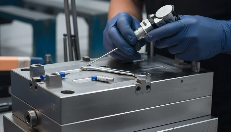
The tightest mold tolerances are achieved through thermally stable machining environments, properly calibrated equipment, optimized cutting parameters for steel grade and hardness, and systematic measurement-correction cycles rather than single-pass machining. In our precision machining cell, we maintain the room temperature at 20±1°C—because a 1°C temperature change in a steel block 500 mm long causes 5.5 µm of thermal expansion, which exceeds the tolerance on many precision features.
Our CNC machining approach for precision mold work uses several key practices. 사출 금형 수축 보상 다이어그램은 캐비티 크기가 최종 부품 치수보다 크게 표시됩니다: the machine warms up for 30 minutes before cutting precision features. Spindle thermal growth is measured and compensated automatically. Steel workpieces are conditioned to room temperature (22°C) before precision cuts.
Chip load optimization for the specific steel hardness: we program higher cutting speeds (150–200 m/min) for P20 at 28–32 HRC and lower speeds (80–120 m/min) for H13 at 44–48 HRC, maintaining consistent chip thickness per tooth. Consistent chip load produces consistent cutting forces, which translates to consistent surface position accuracy.
In-process measurement is the most powerful precision control tool we use. We stop finishing passes at 0.05 mm remaining stock, measure key dimensions on the machine using touch probes, calculate actual deviation from target, and program a final correction pass specifically for any dimensions outside target. This measurement-correction approach achieves ±0.005 mm consistently where single-pass cutting would deliver ±0.015–0.020 mm.
How Does Cooling System Design Impact Part Dimensional Accuracy?
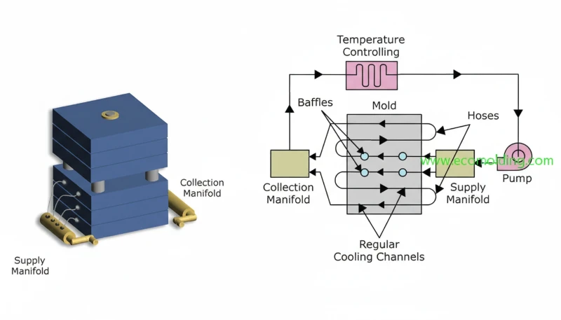
Cooling system design directly impacts dimensional accuracy because non-uniform cooling creates temperature gradients in the part that cause differential shrinkage—leading to warpage and dimensional variation that cannot be corrected by adjusting process parameters. In our factory, we’ve identified poor cooling design as the cause of warpage issues in roughly 30% of the precision mold projects we troubleshoot for customers.
The target for precision molding is uniform cooling: every surface of the part should reach ejection temperature at the same time. This requires cooling channels positioned at consistent depth from the cavity surface (typically 15–20 mm), uniform channel spacing (25–30 mm center-to-center), balanced flow rates across parallel cooling circuits, and—for complex geometry—conformal cooling3 inserts in areas that straight-drilled channels cannot cool adequately.
Water flow rate in cooling channels should maintain turbulent flow (Reynolds number Re > 10,000) for maximum heat transfer efficiency. We calculate required flow rate for each circuit and verify with flow meters during mold setup—many precision mold problems trace back to partially blocked cooling channels with insufficient flow.
Mold temperature control is equally important. We use dedicated temperature control units (TCUs) set to ±1°C accuracy for precision molds, with separate circuits for cavity and core sides. Core temperature is typically run 5–10°C lower than cavity temperature to compensate for the heat flux asymmetry in most part geometries.
What Role Does Mold Assembly Precision Play in Final Part Accuracy?
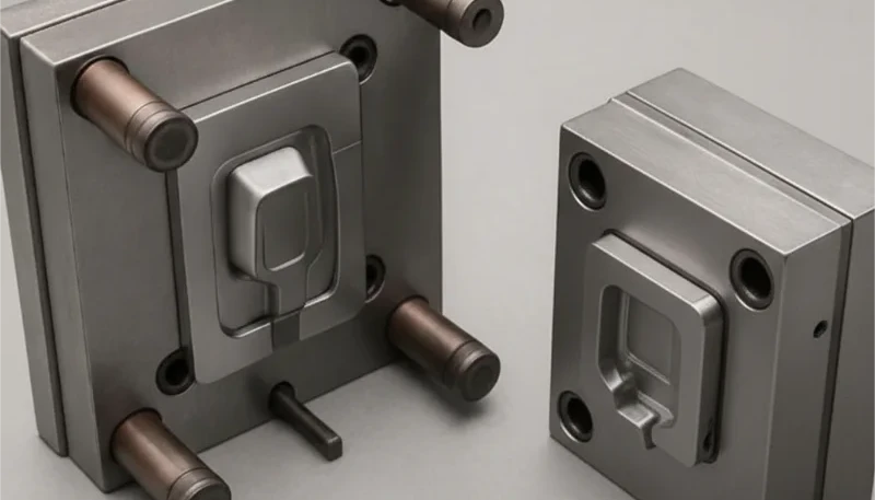
Mold assembly precision determines how accurately the cavity and core halves align when the mold closes, directly affecting parting line quality, wall thickness uniformity, and the dimensional accuracy of features that span the parting line. Even perfectly machined cavity and core inserts will produce poor parts if they’re not assembled and aligned to tight tolerances.
The critical assembly factors for precision molds are: leader pin and bushing fit (we use H7/h6 fits, providing 0.010–0.020 mm clearance per side), parting line flatness (lapped to within 0.005 mm across the mold face), insert seating (precision-ground insert pockets to ensure 100% bearing contact without rocking), and lifter/slider fits (0.02–0.05 mm clearance to allow movement while preventing flash).
We also pay close attention to the ejector plate return system. If ejector pins are not retracted to exactly the same position at cycle start, dimensional variation in part features located over those pins occurs. We use four-pillar guided ejector plates with return springs and check that all pins sit flush to cavity face (±0.02 mm) before approving a mold for production.
“Once a mold is precisely machined, the assembly step is straightforward and doesn’t require special attention.”False
Mold assembly is a precision process in itself. Misaligned inserts, improperly seated leader pins, or a dirty parting surface with trapped debris can introduce positional errors of 0.05–0.2 mm—completely negating the ±0.005 mm machining precision achieved in the shop. Proper assembly requires the same discipline and measurement verification as machining.
“Parting line flatness lapped to within 0.005 mm reduces flash and ensures consistent wall thickness at the parting plane.”True
A flat, clean parting line ensures full contact across the mold face when clamped, preventing flash formation at injection pressures up to 1,400 bar. Uneven parting surfaces—even differences of 0.02 mm—create localized gaps where thin flash forms, and the mold cannot be balanced to eliminate it without addressing the root flatness problem.
How Does Process Control Contribute to Dimensional Consistency?
Process control contributes to dimensional consistency by ensuring that every shot is produced under identical conditions—the same melt temperature, injection velocity profile, hold pressure, cooling time, and ejection timing—so that part-to-part dimensional variation is minimized. We’ve measured that a 5°C melt temperature variation shifts key dimensions by 0.05–0.10 mm on semi-crystalline materials—enough to push a precision part out of tolerance.
Modern all-electric injection machines provide the best repeatability—injection velocity profiles repeat within ±0.1 mm/s, and injection pressure closes within ±1 bar. Hydraulic machines are acceptable for non-precision parts but show ±3–5 bar pressure repeatability that accumulates into dimensional variation on tight-tolerance work.
We implement Statistical Process Control (SPC) on all precision mold dimensions, measuring 5–10 parts per shift and plotting Xbar-R charts for critical dimensions. Our acceptance criterion is Cpk ≥ 1.67 for critical features (equivalent to ±5 sigma) before a new mold is released to full production. This typically requires adjusting process parameters to center the distribution within tolerance, not just confirming that parts are in tolerance at a single operating point.
Frequently Asked Questions About Improving Injection Mold Precision
What is the tightest tolerance achievable in injection molding?
With precision tooling and an optimized process, tolerances of ±0.01–0.02 mm are achievable on small features (under 50 mm) using amorphous materials like PC or ABS. For semi-crystalline materials like PP or PA, ±0.05–0.10 mm is more realistic due to higher and more variable shrinkage rates.
How does material selection affect dimensional precision?
Amorphous materials (PC, ABS, PMMA) have predictable, low shrinkage (0.4–0.8%) and are easier to mold to tight tolerances. Semi-crystalline materials (PP, PA, POM, PEEK) have higher and more variable shrinkage (1.0–3.5%) because the degree of crystallinity depends on cooling rate—making them more sensitive to process variation and harder to hold to tight tolerances.
What is CMM inspection and when is it used for injection molds?
Coordinate Measuring Machine (CMM) inspection uses a precision probe to measure exact 3D coordinates of part features, comparing actual dimensions to CAD nominal values. We use CMM for First Article Inspection (FAI) on all precision parts, measuring 50–200 dimensions and reporting actual vs. nominal with GD&T callouts. CMM accuracy is ±0.002–0.003 mm, more than adequate for validating ±0.05 mm part tolerances.
Can worn molds be brought back to precision tolerances?
Yes, in many cases. Mild wear (0.02–0.05 mm) can be corrected by re-machining critical cavity features and re-polishing. More severe wear requiring cavity build-up is done by laser welding or TIG welding with matching tool steel, followed by full re-machining and re-polishing. We’ve successfully restored production molds to original tolerances at 20–30% of new mold cost.
What is Cpk and why does it matter for injection molding precision?
Cpk (process capability index) measures how well a process fits within its tolerance limits, accounting for both variation width and mean centering. Cpk ≥ 1.33 (4 sigma) is the standard automotive requirement; Cpk ≥ 1.67 (5 sigma) is required for safety-critical dimensions. A mold and process achieving Cpk 1.67 produces fewer than 0.57 defective parts per million—far beyond what visual inspection can achieve.
How often should precision molds be inspected dimensionally?
We recommend dimensional re-inspection of critical cavity features every 100,000–200,000 shots for P20 molds, every 300,000–500,000 shots for H13 molds. Additionally, any time part SPC charts show a dimensional shift—even within tolerance—it’s an early warning of tooling wear requiring inspection before parts go out of spec.
요약
Improving injection mold precision is not a single intervention—it’s a systematic process that spans design, tooling, and production. Each element reinforces the others: excellent shrinkage compensation is wasted without precise machining; precise machining is undermined by unbalanced cooling; balanced cooling doesn’t help if the process drifts. Only when all elements work together does true precision injection molding become consistently achievable.
In our factory, we’ve found that the highest-impact investments for precision are: validated shrinkage modeling (saves multiple dimensional correction cycles), in-process measurement during machining (directly reduces post-cut rework), and rigorous SPC in production (catches dimensional drift before parts go out of tolerance). These three practices deliver the biggest return on investment for any manufacturer pursuing tighter molded part tolerances.
If your parts are currently failing to meet tolerances, the diagnostic approach is systematic: first verify mold dimensions against original design (is the mold correct?), then verify shrinkage compensation accuracy (is the mold design correct?), then analyze process SPC data (is the process stable?). In our experience, this three-step diagnostic finds the root cause within 90% of precision failures.
- Injection moulding is a manufacturing process for producing parts by injecting molten material into a mould (mold). For precision applications, dimensional tolerances and surface finish specifications are critical quality parameters. ↩
-
Shrinkage compensation is the design practice of making mold cavities larger than the desired final part dimensions by the material’s expected shrinkage factor, so that the part reaches target dimensions after cooling and solidification. Typical values range from 0.4% (ABS) to 3.5% (POM). ↩
-
Holding pressure (also called packing pressure) is the injection pressure maintained after initial cavity fill to compensate for volumetric shrinkage during cooling. Typically 50–80% of peak injection pressure, it controls part density, sink mark depth, and dimensional accuracy—particularly in areas far from the gate. ↩
-
Conformal cooling refers to mold cooling channels that follow the contour of the cavity surface at a constant offset distance (typically 10–15 mm), achieving more uniform temperature distribution than straight-drilled channels. Produced via metal additive manufacturing, conformal cooling reduces cycle time by 15–40% and significantly improves dimensional consistency in complex part geometries. ↩


