 콘텐츠로 건너뛰기

PP (폴리프로필렌)fill rate1 rate) is one of the most critical process parameters in injection molding—too slow causes short shots, weld line2 line weakness, and surface blemishes; too fast causes jetting, flash, and burn marks.
– The optimal injection speed for most parts is the fastest speed that fills the cavity without producing quality defects—typically 80–95% of maximum available machine speed for thin-walled parts.
– Fill time should be long enough to avoid jetting (usually >0.5 seconds for most gates) but short enough to prevent premature freeze-off in thin sections (wall thickness × material-specific fill time factor).
– Multi-stage injection (variable speed profiling) is the most powerful approach for complex parts—fast fill in thin runners, slower as the flow front reaches critical features or cosmetic surfaces.
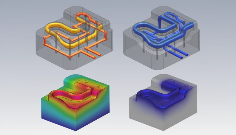
– Mold flow simulation (Moldflow, Moldex3D) should be used to verify injection speed before trialing, particularly for parts with weld lines in structurally critical areas.
What Is Injection Speed and Why Does It Matter So Much?
Injection speed (also called fill rate or injection velocity) is the velocity at which the screw advances to push molten plastic through the nozzle and runner system into the mold cavity, typically expressed in mm/s for screw velocity or cm³/s for volumetric fill rate. It is arguably the single most influential process parameter affecting part quality in injection molding—more so than melt temperature or holding pressure for most surface and structural defects. In our factory, injection speed is the first parameter we adjust when troubleshooting cosmetic defects, short shots, or weld line failures, because getting it right creates a wide, stable process window; getting it wrong cascades into multiple quality problems simultaneously.

The physics of why injection speed matters so much: plastic melt is a non-Newtonian, shear-thinning fluid. Higher injection speeds generate higher shear rates in the gate and runner, which reduce melt viscosity3 and improve flowability—allowing the material to fill thin sections and long flow paths before freezing. But excessive shear generates heat (viscous dissipation), which can degrade the polymer, cause burning at the end of flow, or produce jetting if the flow rate is so high that the melt jet shoots across the cavity rather than spreading progressively from the gate. The challenge is finding the window between these extremes.
| 사출 속도 | Too Slow | Optimal Range | Too Fast |
|---|---|---|---|
| Fill Completion | Short shots, hesitation | Complete, uniform fill | Flash, overpacking |
| Surface Quality | Flow marks, cold slugs | Smooth, consistent finish | Jetting, burning, splay |
| Weld Line Strength | Cold, weak weld lines | Hot, well-knitted weld lines | Degraded polymer at weld |
| Residual Stress | High orientation, warpage | Balanced stress distribution | High shear stress, cracking |
| Mold Wear | Minimal | Normal | Accelerated gate erosion |
How Do You Determine the Starting Injection Speed for a New Mold?
The starting injection speed for a new mold is determined using the rheological fill study (short-shot study) method: begin at 20–30% of maximum machine speed and increase in steps of 5–10%, collecting a part at each setting. Stop at the first speed that produces a complete fill without flash or surface defects. This becomes your baseline. From this point, apply design of experiments (DOE) to optimize around it. The rheological study also identifies the flow front velocity—the speed at which melt moves through the cavity—which should be kept below the jetting threshold (typically 200–500 mm/s at the gate for most resins) while above the hesitation threshold (the speed below which the flow front cools and stalls before filling thin sections).
“Slower injection speed always produces better part quality by reducing shear stress.”False
Slower injection speed causes the flow front to cool more rapidly, increasing freeze-off risk in thin sections, creating cold weld lines, hesitation marks, and potentially incomplete fill. The shear-thinning nature of plastic melt means that higher speeds actually reduce viscosity and improve flow through thin walls. Optimal speed is part- and material-specific—rarely the slowest available.
“The optimal injection speed for most thin-walled parts is 80–95% of the machine’s maximum injection velocity.”True
Thin-walled parts (wall thickness <1.5 mm) have very short freeze windows—often less than 0.3–0.5 seconds. Filling the cavity at high speed (80–95% of machine maximum) is essential to complete fill before the flow front freezes. Slower speeds cause short shots or hesitation marks in thin-wall applications.
What Role Does Material Type Play in Injection Speed Selection?
Material type is a primary determinant of appropriate injection speed range because different polymers have vastly different viscosity-shear relationships, thermal sensitivity, and flow length capability. Shear-thinning materials (most commodity thermoplastics: PP, PE, ABS) respond well to higher injection speeds—viscosity drops significantly with shear rate, improving fill. Thermally sensitive materials (PVC, POM, TPU) require moderated speeds to prevent degradation from viscous heating. Highly filled materials (30–50% glass fiber reinforced PA or PC) need controlled speeds to avoid fiber orientation problems and gate erosion. Here’s a material-specific injection speed guidance summary:

| 재료 | Recommended Speed Range | Key Concern |
|---|---|---|
| PP (polypropylene) | : 사출 단계의 지속 시간은 스크류가 전진하기 시작할 때부터 캐비티가 부피적으로 가득 찰 때까지입니다. 최적의 충전 시간은 일반적으로 부품 크기와 벽 두께에 따라 0.5초에서 3초 사이입니다. | Tiger striping at very high speed |
| ABS | Medium–High (40–80 mm/s) | Burning at gate if too fast |
| PC (polycarbonate) | Medium (30–60 mm/s) | Jetting, splay if too fast |
| PA (nylon) | High (50–90 mm/s) | Flash at parting line if too fast |
| POM (acetal) | Medium (30–60 mm/s) | Thermal degradation, gas marks |
| PVC (rigid) | Low–Medium (20–50 mm/s) | HCl gas release if oversheared |
| Glass-filled PA/PC (30%+) | Medium–High (40–70 mm/s) | Fiber orientation, gate erosion |
What Is Multi-Stage Injection Speed Profiling and When Should You Use It?
Multi-stage injection speed profiling means programming the injection unit to change speed at predefined screw positions during the fill stroke. A typical profile might be: Stage 1 (0–30% fill) at high speed to rapidly fill the runner and gate area; Stage 2 (30–80% fill) at optimal fill speed for the main cavity; Stage 3 (80–100% fill) at reduced speed as the flow approaches cosmetic surfaces, weld lines, or thin features where controlled deceleration improves surface quality. This technique allows the process to be fast where fast is beneficial and slow where slow is necessary—something impossible with single-speed injection.

We use multi-stage injection on virtually every complex part in our facility. A specific example: a large automotive interior trim panel with a highly polished A-surface required injection at 70 mm/s through the gate and main runner (to prevent hesitation marks), dropping to 25 mm/s as the flow front approached the polished cosmetic surface (to eliminate jetting and shear marks), then transitioning to pack pressure at 95% fill completion. Without the speed profile, we could not achieve both complete fill and acceptable surface quality in the same shot.
“Multi-stage injection speed profiling is only necessary for cosmetic consumer products.”False
Multi-stage speed profiling is valuable for structural and functional parts as well as cosmetic ones. It is used to control weld line strength (slow down at weld line locations to increase melt temperature at the knit), manage fiber orientation in filled materials, prevent overpacking in thin sections, and eliminate gate-area jetting in functional components regardless of visible surface requirements.
“Reducing injection speed just before V/P switchover improves pack pressure distribution in parts with thick sections.”True
Decelerating the injection speed in the final 5–10% of fill stroke (approaching switchover from velocity to pressure control) reduces inertia effects and allows the machine control system to switch smoothly. Abrupt V/P switchover at high velocity causes pressure spikes that can cause flash, overpack, or part ejection problems in thick sections.
How Does Gate Size and Design Affect Injection Speed Selection?
Gate size and design profoundly affect the appropriate injection speed by determining the local shear rate experienced by the melt as it transitions from the runner into the cavity. For a given volumetric fill rate, a smaller gate produces much higher local shear rates than a large gate—which can be beneficial (for shear-thinning materials that flow better at high shear) or harmful (causing excessive shear heat, jetting, or gate splay). As a practical rule: pin gates and hot-tip gates require lower injection speeds than edge gates or fan gates of equivalent area; submarine gates fall between the two. When you increase injection speed, monitor for gate-area discoloration (burning), splay, or jetting—the gate is usually the first place quality degrades at excessive speed.
그리고 gate shear rate4 can be calculated from the volumetric fill rate and gate cross-section dimensions. For most amorphous resins, maximum allowable gate shear rate is 50,000–100,000 s⁻¹; for crystalline resins, 20,000–50,000 s⁻¹; and for shear-sensitive materials like PVC and POM, 10,000–30,000 s⁻¹. If your desired injection speed produces gate shear rates above these limits, the gate must be enlarged or the speed reduced.
How Do You Diagnose Injection Speed Problems in Production?
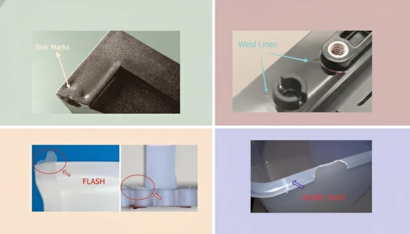
Diagnosing injection speed problems requires connecting observed defects to their speed-related causes. Short shots and hesitation marks indicate insufficient speed or premature freeze-off—increase speed or melt temperature. Jetting (snake-like surface mark emanating from the gate) indicates excessive gate velocity—reduce speed at the gate-fill stage or increase gate size. Burn marks at the end of flow indicate trapped gas from inadequate venting combined with fast fill—improve venting first, then reduce end-of-fill speed if necessary. Flash indicates overpacking or excessive speed at switchover—reduce speed profile in the last 10% of fill. Splay or silver streaks near the gate indicate excessive shear at the gate—reduce speed or enlarge gate.
자주 묻는 질문
What is the difference between injection speed and injection pressure?
Injection speed is the velocity at which the screw pushes melt into the mold (mm/s or cm³/s). Injection pressure is the hydraulic or electric force driving that movement (bar or MPa). During fill, the machine operates in velocity control—maintaining the set speed regardless of pressure (up to the machine’s maximum pressure limit). At V/P switchover, control shifts to pressure mode for packing. Speed and pressure are related but independently controllable on modern machines.
What happens if injection speed is too high for the material?
Excessive injection speed causes shear-induced heating at the gate and runner, leading to polymer degradation (yellowing, burning), jetting across the cavity, splay or silver streaks from volatilized degradation products, and in extreme cases, charred black spots or material breakdown. Thermally sensitive materials like POM, PVC, and PMMA are most vulnerable.
How does wall thickness affect injection speed?
Thinner walls require faster injection speeds to fill before freeze-off. The relationship is approximately: fill time ≤ (wall thickness²) × (material-specific constant). For a 1 mm wall in ABS, fill time must be under 0.3–0.5 seconds; for a 3 mm wall, fill can take 1–3 seconds. Thin-wall molding (under 1 mm) often requires injection speeds exceeding 90% of machine maximum.
Can injection speed affect shrinkage and warpage?
Yes, significantly. Higher injection speeds create greater shear-induced molecular orientation, which leads to anisotropic shrinkage—more shrinkage in the flow direction than perpendicular. This is a primary cause of warpage in flat parts. Balancing injection speed with gate placement and pack pressure is essential to minimize differential shrinkage.
Should I adjust injection speed or melt temperature first when troubleshooting short shots?
Start with injection speed. Increasing injection speed is faster, more precise, and less likely to cause new problems than changing melt temperature (which affects viscosity throughout the cycle, not just fill). If increasing speed to 80–90% of maximum doesn’t resolve the short shot, then consider melt temperature adjustment or gate size increase.
What is V/P (velocity-to-pressure) switchover and how does it relate to injection speed?
V/P switchover is the point during the injection cycle where the machine transitions from velocity-controlled injection to pressure-controlled packing. It is typically set at 90–98% of full cavity volume (by position, pressure, or time). Injection speed at the moment of switchover affects how smoothly the transition occurs—high speeds at switchover cause pressure spikes; gradual speed reduction in the final 5–10% of fill produces smoother pack initiation.
요약
Choosing the right injection speed is neither guesswork nor a single universal answer—it’s a systematic process of understanding your material’s rheological behavior, your part’s geometric fill challenges, your gate system’s shear rate limitations, and your quality requirements at weld lines and cosmetic surfaces. The short-shot study is the essential starting point; multi-stage speed profiling is the most powerful optimization tool; and mold flow simulation provides the analytical foundation that prevents costly trials. In our factory, establishing a correct injection speed profile is the single highest-ROI activity in the first production trial—getting it right the first time saves hours of troubleshooting and prevents the cascade of secondary defects that poor speed selection creates.
-
Gate shear rate is the velocity gradient experienced by the melt as it passes through the gate restriction, calculated as: shear rate (s⁻¹) = (4 × volumetric flow rate) / (π × gate radius³) for circular gates, or equivalent formulas for rectangular gates. Exceeding the material’s maximum allowable shear rate causes thermal degradation, flow instability, and surface defects. ↩
-
Fill time: The duration of the injection phase, from when the screw begins advancing until the cavity is volumetrically full. Optimal fill time typically ranges from 0.5 to 3 seconds depending on part size and wall thickness. ↩
-
점성: A measure of a fluid’s resistance to flow. In injection molding, melt viscosity determines how readily material fills the cavity; higher injection speeds reduce apparent viscosity through shear thinning. ↩
-
Weld line: A visible seam or plane in an injection molded part where two melt fronts meet and fuse. Weld lines can reduce mechanical strength by 10–40% and are minimized by optimizing injection speed and gate location. ↩


