

- Injection molding forces molten plastic into a steel mold at 70–140 MPa; cooling accounts for 50–70% of total cycle time.
- Three machine systems — injection unit, clamping unit, and mold — each play a distinct role in part quality and repeatability.
- At least 15 process variants exist, from gas-assist to scientific molding; choosing the wrong one adds 20–40% scrap rate.
- Material selection drives wall thickness, shrinkage, and temperature: PP shrinks 1.5–2.0%, PC only 0.4–0.8%.
- Draft angle, uniform wall thickness, and a 20-point DFM checklist prevent 80% of first-article failures before the mold is cut.
射出成形とは何か?
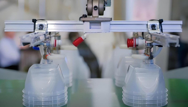
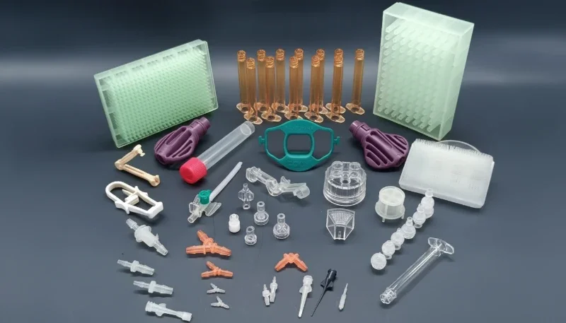
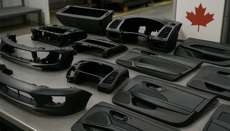
射出成形 is a manufacturing process that melts plastic pellets and forces the melt into a precision steel 射出成形金型 under pressures of 70–140 MPa, producing identical parts in サイクルタイム1s as short as 10 seconds. It is the dominant method for high-volume plastic parts worldwide, covering everything from a two-gram medical cap to a five-kilogram automotive bumper.
The process follows four sequential stages, each with measurable parameters that determine part quality. Understanding each stage helps engineers predict defects before a single pellet is melted. A 2 °C drift in melt temperature or a 0.1-second deviation in hold time can shift part dimensions by 0.05–0.10 mm — enough to fail a tolerance stackup on a precision assembly.
Stage 1 — Plasticating
Plastic pellets enter the feed hopper and travel along a rotating reciprocating screw inside a heated barrel. Barrel temperature zones typically run 180–310 °C depending on the resin. Shear heat from the screw plus conductive heat from the barrel melts the pellets into a homogeneous melt pool ahead of the screw tip. Shot size is set by screw retraction distance; over- or under-shot by more than 5% produces short shots or flash. Material drying before this stage is critical for hygroscopic resins — PA6 and PC must be dried to below 0.02% moisture or the melt will degrade and produce splay, voids, or reduced impact strength.
Stage 2 — Injection
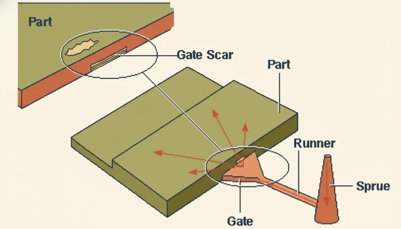
Once the mold is closed and locked, the screw acts as a plunger and drives melt through the runner system and gate into the mold cavity. Injection pressure ranges from 70 to 140 MPa; fill time is typically 0.5–4 seconds. The mold must be fully filled before the gate freezes — usually within 0.1–0.3 seconds of pack pressure switching on. Injection velocity is controlled in multiple steps: fast fill to 95–98% of cavity volume on velocity control, then a velocity-to-pressure transfer for the final fill and pack. Incorrect fill speed causes burn marks from diesel effect at the last-fill area, weld lines at flow fronts, or incomplete fill in thin walls.
Stage 3 — Packing and Holding
After the cavity is 95–98% full on velocity control, the machine switches to pressure control — the pack/hold phase. Hold pressure (typically 50–80% of injection pressure) compensates for volumetric shrinkage as the melt cools. Hold time runs until the gate freezes solid, sealing the cavity — typically 1–10 seconds depending on gate size and material. Too little hold pressure causes sink marks on thick sections; too much causes excessive residual stress, part sticking, and warpage from over-packing. Gate seal time can be determined experimentally by plotting part weight vs. hold time; weight plateaus when the gate is fully frozen.
Stage 4 — Cooling and Ejection
Cooling accounts for 50–70% of total cycle time — the single largest time driver in injection molding. Coolant (water at 10–60 °C) circulates through channels drilled in the mold, extracting heat until the part reaches ejection temperature, typically 60–80 °C below the material’s heat deflection temperature. Ejector pins or plates then push the part out of the cavity. Inadequate cooling causes warpage, dimension drift, and surface defects; over-cooling wastes machine capacity and can create excessive thermal stress in the part.
The entire four-stage cycle repeats automatically, often hundreds of thousands to millions of times over a mold’s service life. Modern machines log every process variable per shot — injection peak pressure, cushion position, cycle time, and barrel temperatures. When a defective part occurs, the machine data identifies the exact cycle and the specific parameter that drifted. This per-shot traceability is one reason injection molding dominates high-volume, tight-tolerance plastic production over competing processes such as thermoforming, blow molding, or rotational molding.
Cycle time economics are equally compelling. A well-optimized 10-second cycle running on a two-cavity mold produces 720 parts per hour. At 85% uptime over three shifts, that is over 14,600 parts per day from a single machine. The marginal cost per part drops sharply with volume, making injection molding the preferred manufacturing route once annual volumes exceed roughly 10,000 parts — and increasingly competitive with 3D printing at much lower volumes when tolerance and surface finish requirements are tight.
What Are the Key Components of an Injection Molding Machine?
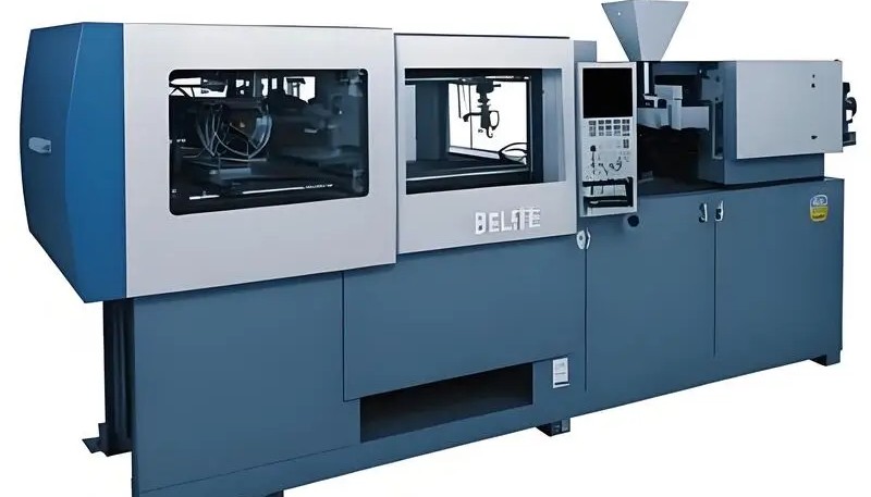
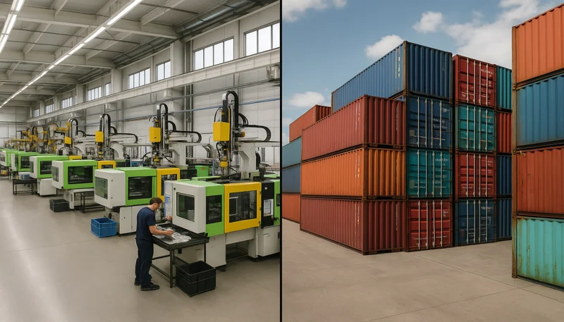
An injection molding machine integrates three interdependent systems — the injection unit, the clamping unit, and the mold — each governing a different phase of the cycle. A mismatch between any two systems produces defects that no amount of process tuning can fully correct. Selecting the right machine size and configuration for a given part is as important as the part design itself.
射出ユニット
The injection unit contains the hopper, barrel, reciprocating screw, heater bands, and nozzle. The screw is the most critical component: its L/D ratio (typically 20:1 to 24:1) and compression ratio (2.5:1 to 3.5:1) govern plasticating capacity and melt homogeneity. Screw diameter directly controls shot capacity — a 40 mm screw typically handles 50–150 g per shot, while an 80 mm screw handles 400–1,200 g. Undersizing the screw for a large part means the screw may not fully plasticize the shot before the next cycle begins; oversizing means material sits in the hot barrel too long and thermally degrades.
Back pressure (typically 5–15 MPa) is applied during screw recovery to improve melt mixing and homogeneity. Higher back pressure produces a more uniform melt but slows recovery time and generates more shear heat — a critical balance for heat-sensitive resins like POM or rigid PVC. The nozzle connects the barrel to the mold sprue; nozzle temperature must stay within ±5 °C of melt temperature to prevent drool between shots or freeze-off that blocks the gate.
Shot-to-shot consistency at the injection unit directly determines dimensional consistency of the part. Cushion — the small amount of melt left in front of the screw at the end of injection — must remain between 3–10 mm. Zero cushion means the screw bottomed out and pressure control was lost; excessive cushion means shot size was set too large and holding pressure transfer was unstable.
クランプユニット
The clamping unit holds the two mold halves closed against injection pressure. Clamping force is measured in metric tons and must exceed the projected cavity area multiplied by average cavity pressure. A common rule of thumb: 2–5 tonnes per square centimeter of projected area, depending on material viscosity and part geometry. For a 100 cm² automotive panel molded in PP at 300 bar average cavity pressure, minimum clamp force = 100 × 300 / 100 = 300 tonnes — a 350- or 400-tonne machine provides the recommended safety margin.
Under-clamped molds flash at the パーティングライン2; over-clamped molds accelerate parting-line wear and increase machine energy consumption by 15–25%. Toggle-clamp machines are faster and more energy-efficient for high-cycle applications; hydraulic full-clamp machines provide smoother, more controllable force build-up for large, complex molds. Tie-bar spacing and platen size must accommodate the mold’s overall footprint — the most commonly overlooked specification when quoting a new mold.
金型
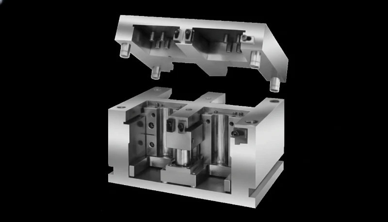
The mold is both a precision tool and a heat exchanger. It contains the cavity (the negative form of the part), core, runner system, gate, cooling channels, vents, and ejection system. Mold steel selection determines surface quality and tool life: P20 is standard for prototype and medium-volume molds (up to 500,000 shots); H13 handles 1M+ shots for abrasive-filled materials; S136 stainless is used for corrosive resins like PVC. Gate location dictates weld-line position, fill balance, and which surface receives a gate vestige.
Runner balance is critical in multi-cavity molds: even 5% runner imbalance causes dimensional and weight variation across cavities, leading to rejects in some cavities while others flash. Scientifically balanced runner systems use naturally balanced (H-tree) layouts or require artificial balancing of runner cross-sections. Cooling channel layout is the most underinvested area in mold design. A poorly cooled mold adds 3–8 seconds per cycle — that extra time compounds to hundreds of thousands of lost production hours over a tool’s lifetime.
What Are the Different Types of Injection Molding Processes?
Standard injection molding handles the majority of plastic parts, but at least 15 process variants exist for applications where standard molding reaches physical limits — thin walls below 1 mm, complex hollow geometry, multi-material designs, or extreme material requirements. Choosing the wrong variant typically adds 20–40% in unnecessary scrap or forces expensive tooling rework after the first production run.
| プロセス | Key Advantage | 代表的なアプリケーション | Trade-off |
|---|---|---|---|
| Standard IM | Low cost, high repeatability | Consumer goods, housings | Single material only |
| オーバーモールディング | Multi-material, soft-touch surface | Handles, grips, wearables | Two-shot tooling cost |
| インサート成形 | Metal-plastic integration | Threaded inserts, connectors | Manual insert loading time |
| Gas-assist IM | Hollow sections, reduced weight | Handles, structural tubes | Gas channel design complexity |
| Water-assist IM | Complex hollow channels | Intake manifolds | Water management system |
| Thin-wall IM | Wall < 1 mm, high L/T ratio | Food packaging, caps | High injection pressure required |
| Micro injection IM | Parts < 1 g | Medical, microelectronics | Specialized equipment needed |
| LSR injection IM | High-temp flexibility, biocompatible | Medical seals, baby products | Long cure cycle |
| リム | Large, lightweight foam parts | Automotive fascias | Chemical mixing system |
| Structural foam IM | Rigid lightweight panels | Office furniture, enclosures | Rough surface finish |
| Co-injection | Rigid core, aesthetic skin | Automotive trim panels | Complex tooling |
| Multi-shot / 2K IM | Two materials, one cycle | Two-tone parts | Rotary mold equipment |
| In-mold decoration | Surface graphics in-mold | Electronics panels | Film positioning precision |
| Vibration/ultrasonic IM | Reduced residence time | Recycled materials | Specialized screw design |
| Scientific Molding | Process-controlled, validated | Medical, aerospace | Requires full DOE study |
Scientific Molding — The Gold Standard for Process Control
Scientific Molding (also called Decoupled Molding III) treats injection molding as an engineering discipline rather than a craft. Developed by John Bozzelli and RJG Inc., the approach separates fill, pack, and cooling into independently optimized, data-driven sub-processes. Instead of relying on machine position or time setpoints, Scientific Molding uses in-cavity pressure sensors and melt temperature verification to anchor the process to measurable physical states that are machine-independent.
A complete Scientific Molding study includes: viscosity curve determination (finding the lowest stable injection speed), gate seal study (optimizing pack and hold pressure), cooling optimization (minimum cycle time without warpage), and a Design of Experiments for process robustness. The resulting process window absorbs normal machine-to-machine and material lot variation without producing defects. Typical outcomes: scrap rates below 0.5%, Cpk greater than 1.67 on critical dimensions, and zero process-related customer complaints across millions of cycles.
For medical devices, aerospace components, and automotive safety parts, Scientific Molding is increasingly a contractual requirement at qualification. It is also the fastest path to first-article approval — a well-executed study compresses mold qualification from 12 weeks to 4–6 weeks by eliminating iterative trial-and-error guesswork.
オーバーモールディング そして インサート成形 are two of the most commercially significant process variants. Overmolding bonds a second polymer — typically a soft TPE — over a rigid substrate to create ergonomic grip surfaces, seals, or aesthetic color breaks without adhesives or assembly. Insert molding encapsulates metal hardware (threaded inserts, electrical contacts, hinge pins) directly in plastic, eliminating secondary press-fit operations and delivering pull-out strength that exceeds assembly methods by 30–50%.

Gas-assist and water-assist molding solve the same structural challenge from different angles: both create hollow sections inside thick-walled parts, eliminating sink marks and reducing weight by 15–30% without increasing cycle time proportionally. Gas-assist is simpler and more widely available; water-assist handles longer, more complex channels at the cost of a pressurized water recovery system. The choice depends on channel geometry, wall uniformity requirements, and available machine infrastructure.
Thin-wall injection molding pushes standard process limits to produce wall thicknesses below 1 mm with length-to-thickness ratios exceeding 150:1 — common in food packaging and disposable cups. It demands injection pressures up to 200 MPa, high-speed injection in under 0.3 seconds, and molds with enhanced cooling to freeze the thin section before it degrades. Structural foam molding takes the opposite approach: using a chemical blowing agent or nitrogen injection to create a cellular core inside a rigid solid skin, reducing part weight by 10–20% and saving material cost on large, thick panels like office furniture and enclosures.
What Plastics Can Be Injection Molded?
Virtually any 熱可塑性3 can be injection molded, and most thermosets with modified tooling; over 25,000 engineered plastic grades are commercially available. The key selection variables are operating temperature, mechanical load, chemical environment, regulatory compliance, and per-part cost target. Selecting the wrong material costs far more than the price difference per kilogram — it costs tooling rework, product recalls, or full re-qualification when the part fails in service.
Three Material Categories
熱可塑性プラスチック are by far the most common injection molding material category — they soften when heated, flow under pressure, and solidify on cooling in a fully reversible physical transition. This reversibility enables regrind, recycling, and reprocessing. Commodity thermoplastics (PP, PE, PS, ABS) cost $1–3/kg and cover the majority of consumer product applications. Engineering thermoplastics (PC, POM, PA, PBT) cost $3–10/kg and target structural or semi-structural applications needing higher temperature resistance or better fatigue life. High-performance thermoplastics (PEEK, PEI, PPS) cost $50–200/kg and handle continuous service above 150 °C or aggressive chemical environments.
Thermosets (epoxy, phenolic, melamine) undergo irreversible cross-linking during cure — they cannot be remelted or recycled. Their advantage is exceptional dimensional stability at elevated temperatures: a phenolic part holds its shape at 180 °C where a PP part would creep significantly. Thermoset injection molding requires heated molds (150–200 °C versus cooled molds for thermoplastics), longer cycle times, and dedicated cleaning between material changeovers. However, thermoset parts command a premium in high-temperature electrical and structural applications.
Elastomers and TPEs bridge the gap between rigid plastics and rubber. Liquid silicone rubber (LSR) is a thermoset elastomer processed by reaction injection at heated molds; thermoplastic elastomers (TPU, TPE, SEBS) process on standard injection equipment and can be overmolded onto rigid substrates. Both are used for seals, grips, gaskets, and flexible overmolded surfaces. The key processing difference: LSR requires mold temperatures of 150–200 °C and platinum catalyst; TPEs run at standard thermoplastic mold temperatures and require no curing.
| 素材 | Min Wall (mm) | Shrinkage (%) | Melt Temp (°C) | HDT (°C) | Typical Use |
|---|---|---|---|---|---|
| PP | 0.8 | 1.5–2.0 | 200–280 | 100–115 | Packaging, living hinges, caps |
| ABS | 1.0 | 0.4–0.7 | 200–260 | 88–108 | Housings, consumer electronics |
| PC | 1.0 | 0.4–0.8 | 260–320 | 130–145 | Optical lenses, enclosures |
| PA6 (Nylon) | 1.0 | 0.8–1.5 | 230–280 | 65 (unfilled) | Gears, brackets, cable ties |
| PA66 (Nylon) | 1.0 | 0.8–1.5 | 260–300 | 75 (unfilled) | Automotive connectors, clips |
| POM (Acetal) | 0.8 | 1.8–2.5 | 185–225 | 100–115 | Precision gears, bearings |
| PBT | 0.8 | 0.8–1.4 | 240–270 | 120–150 | Electrical connectors, relays |
| ISO 10993: | 1.0 | 0.4–0.7 | 230–280 | 105–125 | IT enclosures, bezels |
| TPU | 1.0 | 0.5–2.0 | 185–230 | 60–80 | Flexible seals, cable jackets |
| 覗き見 | 1.0 | 1.2–1.5 | 360–400 | 140 (30% GF: 315) | Medical, aerospace, bearings |
Material Selection Decision Framework
Start with service environment: operating temperature first — the material’s heat deflection temperature must exceed peak service temperature by at least 20 °C for unfilled grades; glass-fiber-filled grades gain 30–80 °C of HDT. Check chemical exposure next: PA absorbs moisture and loses up to 30% tensile strength in wet conditions; POM is incompatible with strong acids; PC degrades in alkaline environments and many solvents. Regulatory compliance narrows the list further — food contact requires FDA-approved resin grades, medical devices need USP Class VI or ISO 10993 biocompatibility, and electronics assemblies often require UL94 V-0 flame rating.
Once technical requirements are satisfied, cost optimization begins. The hidden cost of high-shrinkage materials like POM (1.8–2.5%) and PA66 (0.8–1.5%) is tighter mold compensation requirements and longer dimensional development cycles compared to low-shrinkage materials like ABS (0.4–0.7%) and PC (0.4–0.8%). For tight-tolerance parts, the material’s shrinkage consistency batch-to-batch matters as much as the nominal shrinkage value — a material that shrinks 1.5% ± 0.3% requires a wider mold compensation allowance than one that shrinks 1.5% ± 0.05%.

How Do You Design Parts for Injection Molding?
Design for Manufacturability (DFM4) for injection molding means identifying and resolving every geometric feature, tolerance, or material choice that would cause a defect, add cycle time, or require expensive mold modifications — before the mold is ordered. At ZetarMold, our engineers identify an average of 3.2 DFM issues per submitted part drawing; 38% of those involve incorrect or missing draft angle. Resolving these issues upstream saves weeks of tooling revision time and avoids costs that routinely reach $5,000–20,000 per mold modification.
Wall Thickness Guidelines by Material
Wall thickness is the single most influential design parameter in injection molding. Too thin and the part short-shots during fill or is too fragile in service; too thick and you get sink marks, internal voids, extended cycle time, and wasted material. The target thickness range varies by material because melt viscosity, cooling rate, and solidification shrinkage all differ significantly across resin families.
| 素材 | Minimum (mm) | Recommended (mm) | Maximum (mm) | 備考 |
|---|---|---|---|---|
| PP | 0.8 | 1.5–2.5 | 4.0 | Excellent flow; living hinges at 0.25–0.5 mm |
| ABS | 1.0 | 1.5–3.0 | 4.5 | Good flow; reliable surface finish |
| PC | 1.0 | 2.0–3.5 | 4.0 | High viscosity; gate near thick sections |
| PA6 / PA66 | 1.0 | 1.5–3.0 | 4.0 | Drying critical; moisture affects dimensions |
| POM | 0.8 | 1.5–3.0 | 4.0 | Avoid sections > 4 mm: internal voids |
| PBT | 0.8 | 1.5–2.5 | 4.0 | Fast crystallization; keep thickness uniform |
| TPU | 1.0 | 1.5–3.0 | 5.0 | Flexible; design for intended flex intent |
| 覗き見 | 1.0 | 1.5–3.0 | 4.0 | Mold temp 160–180 °C required |
| LSR | 0.4 | 1.0–3.0 | 6.0 | Thermoset; heated mold; longer cure cycle |
Draft Angle Rules
DFM for injection-molded plastic parts always begins with draft: without draft, parts drag along the mold surface during ejection, leaving scuff marks, causing sticking, and accelerating tool wear. The required draft angle depends on surface texture and draw depth.
For smooth (polished) surfaces: minimum 1° draft per 25 mm of draw depth. For light texture (MT-11020 equivalent): 1.5° minimum. For medium texture: 2.0° minimum. For heavy texture (leather grain, MT-11030): 3.0° minimum — add 1° per 0.025 mm of texture depth as a general design rule. Deep ribs with depth greater than 5× their width need extra draft beyond the nominal surface angle: add 0.5–1° to prevent rib walls sticking during ejection. Side walls on textured parts with 0° draft show white stress marks and scratching within the first 1,000 production shots.
20-Point DFM Checklist for Injection Molding
| # | Check Item | Rule / Target | Risk If Ignored |
|---|---|---|---|
| 1 | Wall thickness uniformity | Variation ≤ 25% of nominal | Sink marks, voids, warpage |
| 2 | Draft — smooth surface | ≥ 1° per 25 mm draw depth | Ejection drag, surface scuffs |
| 3 | Draft — textured surface | ≥ 1.5° light, ≥ 3° heavy texture | Texture tearout, white marks |
| 4 | Rib thickness | 50–60% of adjacent wall | Sink marks on opposite face |
| 5 | Rib draft | 0.5–1° beyond nominal draft | Rib sticking, accelerated tool wear |
| 6 | Boss design | OD = 2× hole diameter; 0.5° draft | Boss sink, weak joint |
| 7 | Undercut review | Eliminate or add sliding action | Mold damage, stuck parts |
| 8 | Gate location | Thick-to-thin fill, non-cosmetic surface | Short shot or weld line on A-surface |
| 9 | Weld line location | Away from stress concentration | Structural failure at weld |
| 10 | Parting line logic | Flat or matched step; no sharp angle | Flash, dimensional shift |
| 11 | Ejector pin placement | Non-cosmetic surface, near tall features | Part distortion on ejection |
| 12 | Corner radii | Min 0.5 mm internal, 1.0 mm external | Stress concentration, flow hesitation |
| 13 | Minimum feature size | Wall ≥ minimum for material | Short shot, fragile thin sections |
| 14 | Hole / slot orientation | Parallel to draw or add side action | Undercut = expensive slide |
| 15 | Thread design | External: split parting line; internal: collapsible core | Stuck part or core damage |
| 16 | Snap fit geometry | Deflection ≤ 2% strain (ABS); ≤ 4% (PP) | Snap fracture on first assembly |
| 17 | Living hinge (PP only) | 0.25–0.5 mm thick; gate perpendicular | Hinge fracture on flexing |
| 18 | Surface finish spec | Match SPI finish class to mold steel | Mismatch costs polishing or remachining |
| 19 | Shrinkage compensation | Mold scaled at nominal + material shrinkage | Out-of-tolerance first article |
| 20 | Cooling channel proximity | Coolant within 2× channel diameter of cavity | Hot spots, warpage, excess cycle |
Not every DFM finding is equally urgent. Priority tier 1 items — draft, wall thickness, undercuts — must be resolved before mold order because they require physical steel removal or addition to fix. Tier 2 items — gate location, ejector placement, runner design — should be confirmed at DFM review but can sometimes be adjusted by modifying insert positions. Tier 3 items — surface finish spec, text depth, logo placement — can be addressed in process notes during mold qualification.
Running a DFM study when the 3D model is 80% complete compresses total project time by 3–6 weeks on average. The cost of a DFM review is typically $200–500; the cost of a mold modification after steel is cut ranges from $2,000 to $20,000. That is a 10–40× return on a single early-stage engineering conversation. Parts that arrive with all 20 DFM points addressed universally reduce first-article tooling revisions by over 60% and reach production sampling 3–4 weeks faster than parts with unresolved geometry issues.
Factory Insight: At ZetarMold, our engineers identify an average of 3.2 DFM issues per submitted part drawing. The most common single issue — found in 38% of all part reviews — is missing or insufficient draft angle, particularly on textured side walls and deep ribs. Parts that arrive with draft properly applied across all surfaces reduce first-article tooling revisions by over 60% and reach first sample inspection 3–4 weeks earlier than designs where draft was an afterthought.
What Process Parameters Control Injection Molding Quality?
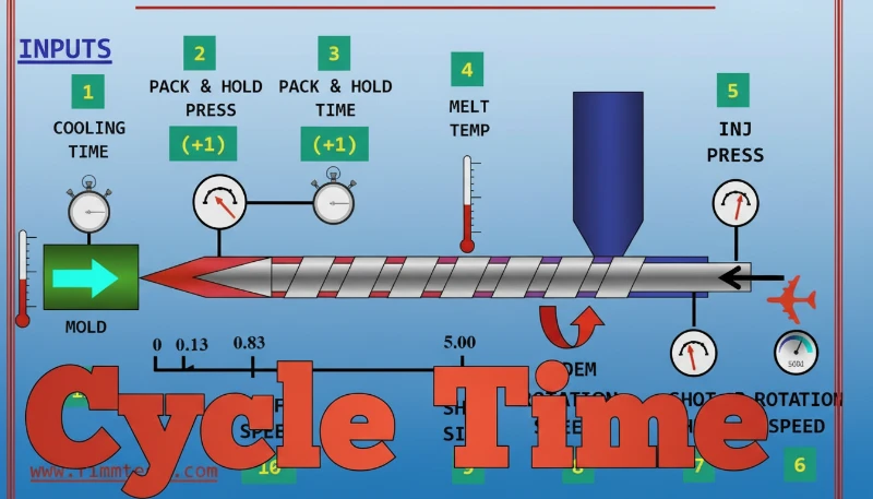
Six process parameters govern injection molding quality: melt temperature, mold temperature, injection speed, holding pressure, cooling time, and back pressure — and each interacts with the others in ways that change completely depending on which resin you are running. A setting that produces perfect ABS parts will cause flash and warpage in PC; the parameters are not transferable across materials. Refer to our guide on the プラスチック射出成形プロセス for the foundational mechanics behind each stage.
| パラメータ | PP | ABS | PC | PA6 |
|---|---|---|---|---|
| Melt Temperature (°C) | 200–280 | 220–260 | 270–320 | 230–280 |
| Mold Temperature (°C) | 20–60 | 40-80 | 70–120 | 40–90 |
| Injection Speed (mm/s) | 60–150 | 40–120 | 20–80 | 50–130 |
| Holding Pressure (% of injection) | 50–70% | 55–75% | 60–80% | 50–70% |
| Cooling Time (% of cycle) | 50–65% | 55–70% | 60–75% | 50–65% |
| 背圧 (MPa) | 0.3–0.8 | 0.5–1.0 | 0.5–1.2 | 0.3–0.8 |
溶融温度 is the most frequently misadjusted parameter. Running too hot degrades the resin — PC shows yellowing and reduced impact strength above 330 °C, while PA6 begins to hydrolyze above 295 °C if moisture is not controlled. Running too cold causes short shots and weld lines. The correct set point is the midpoint of the resin manufacturer’s recommended range, then adjusted ±5–10 °C based on T1 sample results.
金型温度 is often underestimated. Many processors set it once and never revisit it. For PC, a mold running at 50 °C instead of the recommended 90 °C will produce parts with higher residual stress, increased warp under service load, and a surface gloss that drops by 10–20 GU. PP crystallinity is also mold-temperature dependent: higher mold temps increase crystallinity, improve stiffness, and reduce post-mold shrinkage variation — critical for tight-tolerance parts.
射出速度 controls shear rate and fill front behavior. Fast injection fills thin walls before they freeze, but generates more shear heat — beneficial for PA6, dangerous for heat-sensitive PVC. Multi-stage velocity profiles are standard practice: ramp up to 80–90% fill, decelerate to 30–50% before transfer, preventing pressure spikes at transfer that cause flash. Jetting — a wavy surface defect — occurs when melt speed at the gate is too high relative to cavity geometry; reducing injection speed in the first 10–15% of fill eliminates it.

保持圧力 is gate-seal insurance. The correct hold pressure keeps cavity pressure above the resin’s solidification pressure until the gate freezes. Set too low: sink marks appear over ribs and bosses because the shrinking core is not compensated. Set too high: the part sticks to the core, ejector pins leave marks, and residual stress builds up at the gate area, causing delayed cracking under load in PC and polycarbonate alloys. Gate seal time — determined by part weight vs. hold time plot — is the most reliable method to set hold time correctly.
冷却時間 is where most cycle time waste hides. The goal is to cool the thickest wall section below the resin’s ejection temperature — typically HDT minus 20–30 °C. Rule of thumb: cooling time scales with the square of maximum wall thickness. Double the wall thickness → four times the cooling time. Uneven cooling is more dangerous than long cooling: a 10 °C temperature differential across the part drives warp. Conformal cooling channels, designed to follow the cavity contour, reduce differential by 60–80% versus straight-drill cooling.
背圧 controls melt homogeneity during plastication. Higher back pressure increases shear mixing, eliminates unmelted pellets, and disperses colorant uniformly — but also generates more shear heat and extends cycle time. For standard amorphous resins like ABS and PC, 0.5–1.0 MPa is typical. For crystalline resins with poor thermal conductivity like PP, 0.3–0.6 MPa is sufficient. Never exceed 1.5 MPa for shear-sensitive materials such as PVC or long-fiber reinforced compounds — fiber breakage and degradation follow immediately.
Parameter interactions create defects that no single adjustment can fix. Flash and short shots are not opposite ends of one dial — they can appear simultaneously on the same part if injection speed is too high (flash at the parting line from pressure spike) while hold pressure is too low (short shot at the last-fill area). Understanding the cause-and-effect chain — rather than adjusting one parameter at a time — is the difference between a two-hour process setup and a two-week one.
What Are Injection Molding Tolerances and How Do You Achieve Them?
Injection molding tolerances fall into three tiers: general ±0.1–0.2 mm for commodity parts, precision ±0.05 mm for functional assemblies, and ultra-precision ±0.02 mm for medical and optical components — each tier requiring progressively better mold steel, process control, and material selection. Knowing which tier your part actually needs is the first cost decision, because moving from general to precision tolerance can double mold cost and require temperature-controlled press rooms.
| Tolerance Tier | Range | 代表的なアプリケーション | Required Process Control |
|---|---|---|---|
| 一般 | ±0.1–0.2 mm | Consumer housings, brackets | Standard mold steel, basic process window |
| 精密 | ±0.05 mm | Connectors, gears, snap-fits | H13/S136 steel, scientific molding |
| Ultra-Precision | ±0.02 mm | Medical, optics, micro parts | Temperature-controlled room, closed-loop control |
Shrinkage rate is the first variable to quantify when setting tolerance targets. Each resin has a characteristic volumetric shrinkage that must be compensated in the mold cavity dimensions. The cavity is machined oversized by the predicted shrinkage amount so the cooled part hits the nominal dimension. If shrinkage is not predicted accurately, every part produced will carry a systematic dimensional error that no process adjustment can correct without steel rework.
| 素材 | 収縮率 | Dimensional Impact per 100 mm | 備考 |
|---|---|---|---|
| PP (Homopolymer) | 1.5–2.5% | 1.5–2.5 mm | High crystallinity; anisotropic with fiber fill |
| ABS | 0.4–0.7% | 0.4–0.7 mm | Consistent; low anisotropy — preferred for precision |
| PC | 0.5–0.7% | 0.5–0.7 mm | Very consistent; ideal for optical and medical tolerances |
| PA6 (Unfilled) | 0.6–1.4% | 0.6–1.4 mm | Moisture-dependent; must be measured at equilibrium moisture content |
| PA6-GF30 | 0.2–0.8% | 0.2–0.8 mm | Flow-direction vs. transverse shrinkage differ by 0.4–0.6% |
Three factors drive whether a mold achieves its targeted tolerance tier consistently.
Factor 1 — Mold steel and machining quality. General tolerance parts can be produced from P20 pre-hardened steel machined to ±0.05 mm. Precision parts require H13 or S136 hardened to 48–52 HRC, with EDM finishing on critical surfaces to ±0.01 mm. Ultra-precision optical or medical tools use stainless S136H polished to mirror finish (Ra ≤ 0.025 μm). The mold steel grade sets the ceiling; no process optimization can compensate for a cavity machined with insufficient accuracy.
Factor 2 — Process window stability. A stable process is the prerequisite for repeatable dimensions. Melt temperature variation of ±5 °C changes PC part dimensions by 0.01–0.03 mm per 100 mm of length. For precision parts, this must be controlled by closed-loop barrel temperature controllers (±1 °C accuracy), consistent shot size repeatability (±0.1% stroke), and documented switch-over position that does not drift across a production run. Scientific molding protocols — documenting cavity pressure profiles, not just machine settings — achieve shot-to-shot repeatability that correlates directly to dimensional consistency.
Factor 3 — Part and mold design. Uniform wall thickness is the single most impactful design decision for tolerance control. Non-uniform walls cool at different rates, generating internal stresses that cause warpage — a dimensional error no gating or cooling change can fully eliminate. Ribs at 50–60% of nominal wall thickness minimize differential shrinkage. Gate location on the heaviest cross-section ensures pack pressure reaches all areas before freeze-off. Symmetrical cooling channel layout — equal distance from cavity on both core and cavity sides — prevents differential thermal contraction across the parting line.
The practical implication: do not over-specify tolerances. Every 0.01 mm tighter than necessary adds cost in machining, inspection, and scrap rate. The correct approach is to do a tolerance stackup analysis on the assembly, find the critical dimensions that actually matter, and specify precision tolerances only on those — leaving the rest at general commercial tolerance. A part with three critical dimensions at ±0.05 mm and fifteen non-critical dimensions at ±0.15 mm is easier to produce and costs less than one with all eighteen dimensions at ±0.05 mm.
What Are the Advantages and Disadvantages of Injection Molding?
Injection molding’s core advantage is reproducibility at scale: once the mold is tuned, every part is a near-perfect copy of the last — with cycle times as short as 10 seconds and dimensional variation under ±0.1 mm across millions of parts. Its core disadvantage is front-loaded cost: tooling runs $3,000–$100,000+ before a single saleable part ships. The economics only work above a volume threshold that most buyers underestimate.
Advantages in detail:
High repeatability and dimensional consistency. Injection molded parts hold tolerances of ±0.1–0.2 mm commercially, ±0.05 mm with precision tooling, across millions of shots. No other polymer process — thermoforming, blow molding, or 3D printing — matches this shot-to-shot repeatability at production volumes.
Production efficiency. Cycle times of 10–120 seconds and multi-cavity molds (4, 8, 16, 32, or more cavities per mold) mean a single press can produce thousands to tens of thousands of parts per shift. A 16-cavity PC lens tool running a 25-second cycle produces 2,304 parts per hour — a rate no subtractive or additive process can match at equivalent cost.
Material versatility. Over 25,000 engineered plastic compounds are commercially available for injection molding, covering applications from -40 °C cryogenic environments to 300 °C continuous service, from transparent optical grades to electrically conductive formulations. The same machine can run commodity PP in the morning and PEEK aerospace parts in the afternoon, with a material purge and barrel temperature change between runs.
Complex geometry in a single operation. Undercuts, internal channels, living hinges, snap-fit features, threads, and overmolded inserts are all achievable without secondary operations. A part that would require five machined components can be injection molded as one — eliminating assembly labor, fasteners, and tolerance stackup between parts.
Low per-unit material waste. Runner systems recycle directly back into production. Hot runner systems eliminate runner waste entirely, with material utilization above 98% — compared to 40–60% utilization typical in CNC machining of plastic blocks.
Disadvantages in detail:
High initial tooling cost. A production steel mold for a moderately complex part costs $10,000–$50,000 and takes 4–8 weeks to build. This capital is sunk before any parts are made. If the design changes after tooling is cut, mold modification costs $1,000–$10,000 per change, and some geometry changes require scrapping the mold entirely. Aluminum prototype molds reduce upfront cost to $2,000–$8,000 but have a limited tool life (10,000–50,000 shots vs. 500,000–1,000,000+ for hardened steel).
Design constraints. Draft angles (0.5°–5°), uniform wall thickness, and parting line placement are mandatory design disciplines — not optional. Complex geometries with severe undercuts require side-actions or collapsible cores that add $2,000–$20,000 to mold cost per feature. Design freedom is lower than CNC machining or 3D printing, where the tool can reach any surface.
Long setup lead time. Even a simple mold takes 2–4 weeks from approval to T1 samples. Engineering changes mid-production require machine downtime and potential mold modification. For products with rapid design iteration cycles, this lead time is a structural disadvantage.
Minimum volume threshold. At very low quantities, the per-part tooling amortization makes injection molding economically uncompetitive. Below 50 units, 3D printing or CNC machining is almost always cheaper on a total-cost basis.
“Injection molding becomes cost-competitive at production volumes above 150 units, where the tooling cost amortizes below per-unit savings.”真
At 150 units, a $3,000 aluminum prototype mold adds $20 per part in tooling amortization. Combined with a per-part material and machine cost of $0.50–$2.00, the total cost is competitive with CNC-machined plastic parts at $25–$80 each. By 500 units, injection molding is typically 40–60% cheaper per part than CNC or 3D printing for the same geometry.
“Injection molding always requires expensive tooling — aluminum prototype molds start at under $2,000 for simple parts.”偽
Aluminum molds for simple single-cavity parts with no side-actions or complex cooling can be quoted at $1,500–$3,000 from Chinese toolmakers. These tools are rated for 10,000–50,000 shots — enough to bridge from prototype validation to the volume that justifies a production steel mold. ‘Injection molding requires expensive tooling’ is true for production-grade P20 or H13 steel molds, not for the full tooling spectrum.
How Does Injection Molding Compare to 3D Printing and CNC Machining?
The three most common plastic manufacturing processes serve different volume, tolerance, and geometry needs — and the decision framework comes down to quantity, complexity, and whether you can afford to wait 4–8 weeks for tooling. The quick rule: under 50 parts, use 3D printing; 50–500 parts, use aluminum tooling or CNC; above 500 parts with a stable design, injection molding’s per-unit cost advantage becomes decisive.
| Dimension | 射出成形 | 3D Printing (FDM/SLA) | CNC加工 |
|---|---|---|---|
| Tooling/Setup Cost | $3,000–$100,000+ | $0–$500 (file prep) | $200–$2,000 (fixturing) |
| Per-Unit Cost (1,000 pcs) | $0.50–$5.00 | $8–$80 | $15–$150 |
| 寸法公差 | ±0.1–0.2 mm (general), ±0.05 mm (precision) | ±0.2–0.5 mm (FDM), ±0.05–0.1 mm (SLA) | ±0.025–0.05 mm (plastic), ±0.005–0.025 mm (metal) |
| 素材オプション | 25,000+ compounds | Limited (50–200 options) | Broad (plastics + metals) |
| Lead Time to First Part | 4–8 weeks (tooling) | 1–3 days | 3–10 days |
| Ideal Volume Range | 500–10,000,000+ | 1–200 units | 1–500 units |
3Dプリンティング — specifically FDM and SLA — wins on speed and design freedom. Parts with undercuts in every direction, internal lattice structures, and geometries impossible to mold can be printed without tooling. Lead time is 1–3 days versus 4–8 weeks for injection molding. The tradeoff: per-unit cost scales linearly with quantity (each part costs the same as the last), while injection molding’s per-unit cost falls as volume rises. At low quantities, 3D printing’s zero tooling cost dominates. At high quantities, injection molding’s sub-$1 cycle economics win by an order of magnitude.
Surface finish and material properties are also limiting for 3D printing. FDM parts have visible layer lines (Ra 10–30 μm), anisotropic strength (40–60% weaker in the Z-axis), and limited material options compared to injection molding’s full thermoplastic library. SLA produces better surface finish and isotropic properties but uses photopolymer resins that are brittle, UV-sensitive, and not approved for most food-contact or medical applications without secondary processing. For functional prototypes or pre-production validation, 3D printing is excellent. For load-bearing production parts, it rarely competes with injection molding on strength or consistency.
CNC加工 offers the tightest tolerances of the three processes. For metal parts — aluminum, steel, titanium — CNC achieves ±0.005–0.025 mm routinely. For plastic parts, ±0.025–0.05 mm is achievable with proper fixturing and stable materials. This makes CNC the right choice for one-off precision components, jigs, fixtures, and parts where material certification (aerospace, defense) requires wrought stock traceability — something injection molded parts cannot provide.
“CNC machining achieves ±0.025mm tolerances for metal parts, tighter than injection molding’s typical ±0.1–0.2mm for plastics.”真
CNC machining of aluminum and steel regularly holds ±0.005–0.025 mm for precision features — an order of magnitude tighter than commercial injection molding tolerances. Even precision injection molding with H13 steel molds and closed-loop process control targets ±0.02–0.05 mm on critical dimensions, which is the lower limit of what’s economically achievable in plastic. For metal structural components requiring sub-0.05 mm fits, CNC remains the correct process choice.
“3D printing is always faster than injection molding — for orders above 200 units, injection molding cycle times make it significantly faster per part.”偽
A 3D printer producing one part at a time in 2–8 hours per part is slower than an injection molding press cycling every 15–30 seconds. At 200 units, a single-cavity mold running a 20-second cycle produces all 200 parts in 67 minutes of machine time, versus 400–1,600 hours for FDM printing. The ‘3D printing is faster’ claim applies only to lead time to first part — not throughput at production quantities. Total time including mold build: injection molding leads above 500 units with a stable design.
The quantified decision framework: use this to choose the right process before committing budget.
| ボリューム | Recommended Process | Typical Tooling | Total Cost Rationale |
|---|---|---|---|
| 1–50 units | 3D Printing (SLA/FDM/MJF) | None | Zero tooling cost dominates; per-unit cost irrelevant at this scale |
| 50–500 units | Aluminum mold IM or CNC machining | $2,000–$8,000 (Al mold) | Tooling amortizes acceptably; CNC if geometry has severe undercuts |
| 500–10,000 units | Injection molding (P20 steel mold) | $8,000–$30,000 | Per-unit cost drops below CNC; tooling fully amortized in first 5,000 shots |
| 10,000+ units | Injection molding (H13 multi-cavity) | $30,000–$100,000+ | Multi-cavity tooling pushes per-unit cost to cents; ROI positive at scale |
For the injection molding vs. 3D printing decision in more technical depth — including material property comparisons and hybrid workflows — we’ve covered the full analysis separately. If your project involves metal components or ultra-tight plastic tolerances, the CNC加工 guide walks through fixturing, feed rate, and material stability factors that determine whether CNC is the right final manufacturing method or just a bridge before tooling investment.
What Are Common Injection Molding Defects and How Do You Fix Them?
Twelve injection molding defects account for over 90% of quality failures in production — and each has a documented root cause, a process correction, and a design prevention that eliminates recurrence. Fixing defects after tooling is cut costs 10–100× more than preventing them in DFM; the table below gives both the reactive process fix and the proactive design change that makes it unnecessary.
| 欠陥 | Visual Characteristic | Primary Cause | Process Fix | Design Prevention |
|---|---|---|---|---|
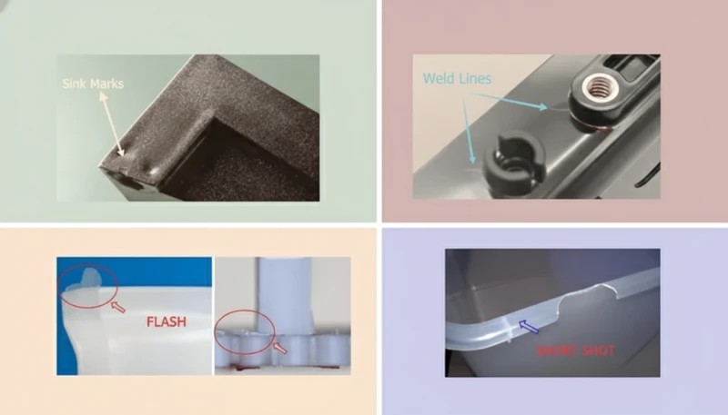
| シンクマーク | Depressions on surface opposite thick sections or ribs | Insufficient hold pressure; gate freeze-off before shrinkage compensated | Increase hold pressure 10–15%; extend hold time until gate seals; lower mold temperature | Limit rib thickness to 50–60% of nominal wall; avoid wall sections >4 mm without coring |
| ワーピング | Part curves, bows, or twists after ejection | Non-uniform cooling creates internal stress gradients; asymmetric wall thickness | Balance mold temperature on core vs. cavity; extend cooling time; reduce hold pressure | Design uniform wall thickness; symmetrical geometry; add ribbing to replace thick walls |
| 溶接ライン | Visible seam or weak line where two flow fronts meet | Two melt fronts meeting at low temperature and pressure; insufficient material welding | Increase melt and mold temperature; increase injection speed; relocate gate to eliminate flow convergence | Position gate so flow fronts merge at non-structural, non-visible surfaces; avoid features that split flow |
| フラッシュ | Thin fin of plastic along parting line, vent, or ejector pin | Excessive injection pressure or speed; worn or misaligned parting line; insufficient clamp force | Reduce injection speed and peak pressure; increase clamp tonnage; check parting line for wear | Design parting line on flat, easily machinable surface; avoid sharp corners at PL that cause wear |
| ショートショット | Incomplete fill; missing features or thin-out at last-fill area | Insufficient injection pressure or speed; gate too small; melt too cold; inadequate venting | Increase melt temperature, injection pressure, and speed; add or enlarge vents at last-fill location | Design wall thickness ≥ 0.8 mm (material-dependent); add vents at last-fill locations during mold design |
| 火傷の跡 | Brown or black discoloration at last-fill area or vent locations | Diesel effect: trapped air compresses and auto-ignites; resin thermal degradation | Add or deepen vents at last-fill area (0.01–0.025 mm depth); reduce injection speed at end of fill | Design adequate venting during tool design; avoid dead-end features that trap air |
| ジェット噴射 | Wavy, snake-like surface pattern from gate area | Melt enters cavity as a free jet rather than a laminar flow front; gate-to-wall ratio too high | Reduce injection speed at start of fill; switch to fan or tab gate; use lower injection temperature | Size gate to produce a wall thickness ≥ 80% of melt diameter at gate; fan gate preferred for flat parts |
| Splay / Silver Streaks | Silver or white streaks on surface, parallel to flow direction | Moisture in hygroscopic resin; overheating causing degradation; air entrainment | Dry material to specified moisture level (PA6 <0.2%, PC <0.02%); reduce melt temperature; increase back pressure | Specify drying requirements in process sheet; design adequate hopper dryer capacity for production rate |
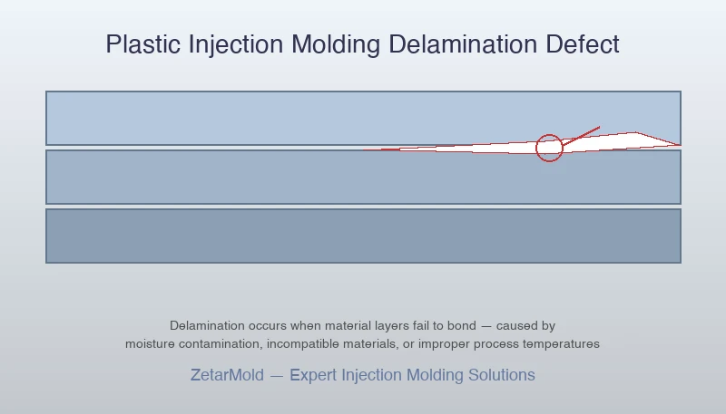
| Delamination | Surface peels off in thin layers; flaking appearance | Incompatible material contamination; excessive shear stress at gate; moisture in resin | Purge barrel thoroughly between material changes; reduce injection speed at gate; dry material | Avoid mixing resin grades; define material change procedures; design gate size to minimize shear rate |
| Bubbles / Voids | Internal voids visible in transparent parts; hollow sections on cross-section | Rapid outer shell freezing traps volumetric shrinkage as internal void; insufficient pack pressure | Increase hold pressure and time; slow cooling rate; increase mold temperature | Reduce maximum wall thickness below 4 mm; core out thick sections; design ribs instead of solid walls |
| Discoloration | Color variation from lot to lot; streaks or spots of different color | Resin degradation from overheating; regrind contamination; colorant mixing issues | Reduce melt temperature and residence time; purge barrel; reduce back pressure; check colorant dispersion | Specify natural resin + masterbatch (not pre-colored pellets) for critical color applications; control regrind ratio ≤15% |
| Dimensional Variation | Parts out of tolerance; dimensions shift between shots or lots | Process instability (temperature, pressure, timing drift); inconsistent material lot shrinkage | Implement scientific molding: document and lock in cavity pressure profile; control material lot shrinkage data | Design to general tolerance wherever possible; apply precision tolerance only to functional critical dimensions |
Two defects deserve additional context because they are most frequently misdiagnosed in production environments.
Splay / Silver Streaks. Most processors immediately suspect wet material when they see silver streaks — and the response is a 4–6 hour redrying cycle. In our experience, 60–70% of splay cases are actually venting or shear problems, not moisture. Before redrying, check: Are vents clear? Is injection speed too high in the gate zone? Has the barrel temperature drifted up during a long production run? A 0.01–0.02 mm vent depth increase often resolves splay in 20 minutes that a redry cycle would not fix in 6 hours.
Warping. Warping is the most process-resistant defect because it is fundamentally a design problem masquerading as a process problem. You can minimize warping through cooling time, mold temperature, and hold pressure optimization — but a part with 6 mm walls adjacent to 1.5 mm walls will always warp to some degree because the differential cooling rate creates differential shrinkage, and no process adjustment eliminates differential shrinkage. The only permanent fix is redesigning the wall to be uniform, or accepting the warp and correcting for it in fixture design.
Defect prevention is always cheaper than defect correction. A DFM review before tooling that catches five potential defect sources costs 4–8 hours of engineer time. Fixing those same issues after T1 samples costs 2–8 weeks of mold modification, production delay, and potential scrap — often 20–50× the DFM cost. The 12 defects in this table all have design-stage solutions; apply them before signing off on the mold design.
射出成形のコストは?
Injection molding cost splits into two entirely different numbers that buyers routinely confuse: tooling cost ($500–$100,000+) is a one-time capital expense, while per-unit part cost ($0.02–$10.00) is the recurring production cost — and understanding which one is limiting your economics changes every decision downstream. Use our injection moulding cost estimator to get a project-specific number before reading the framework below.

| 金型タイプ | Simple Part | Medium Part | Complex Part |
|---|---|---|---|
| Prototype Aluminum | $500–$2,000 | $2,000–$5,000 | $5,000–$8,000 |
| Bridge Tool (P20 Steel) | $3,000–$8,000 | $8,000–$20,000 | $20,000–$40,000 |
| Production (H13 Steel) | $8,000–$20,000 | $20,000–$50,000 | $50,000–$100,000+ |
Prototype aluminum molds are single-cavity, hand-polished, and rated for 10,000–50,000 shots — fast to cut (1–2 weeks) but cannot hold ±0.05 mm tolerances across a full production run. Bridge P20 tools handle 100,000–500,000 shots and bridge the gap between prototype validation and full production investment. H13 hardened steel molds — the production standard — hold 500,000 to 1,000,000+ shots with dimensional repeatability of ±0.05 mm or better, and justify their cost only above 10,000 units.
Per-Unit Part Cost Breakdown
At 10,000 units using a mid-range P20 mold priced at $15,000, the four cost drivers typically break down as follows: tooling amortization accounts for $0.30–$1.50 per part (depending on total run volume), raw material contributes $0.10–$2.00 per part (resin price × shot weight × runner ratio), labor and machine time add $0.05–$0.80 per part at Chinese rates versus $0.50–$3.00 in the US or Europe, and packaging, quality inspection, and logistics add $0.05–$0.30 per part. At 50,000 units, tooling amortization per part drops by 5×, often making injection molding the cheapest option by a significant margin.
| Cost Element | China | USA | Europe |
|---|---|---|---|
| Simple mold (P20) | $3,000–$8,000 | $15,000–$35,000 | $18,000–$45,000 |
| Per-unit cost (10K pcs, ABS) | $0.15–$0.60 | $0.80–$2.50 | $1.00–$3.50 |
| Lead time to T1 samples | 3–5 weeks | 6–10 weeks | 7–12 weeks |
| DFM review included? | Yes (standard) | Often extra cost | Often extra cost |
| Best for | Cost-sensitive volume | IP-sensitive, ITAR | EU compliance, nearshore |
China-based tooling costs 60–80% less than equivalent US or European tooling due to lower labor rates, concentrated tooling supply chains in Guangdong and Zhejiang provinces, and infrastructure built specifically for mold manufacturing at scale. The cost gap is structural, not cyclical — it persists even after shipping, import duties, and quality-assurance travel costs are factored in, for most commercial applications.
8 Proven Ways to Reduce Injection Molding Costs
Cost reduction starts in the design phase, not the quotation phase. Here are eight techniques, ranked by impact: (1) Eliminate unnecessary side-actions — each lifter or slider adds $1,500–$5,000 to mold cost; redesign undercuts as snap-fits or living hinges where function permits. (2) Standardize wall thickness — uniform walls reduce cooling time by up to 30%, directly cutting cycle time and machine cost per shot. (3) Increase draft angles — adding 1° more draft on deep ribs prevents ejection drag, reducing scrap rate and mold maintenance cost.
(4) Choose the right material grade — a commodity PP costs $1.20/kg while a 30% glass-filled PA66 runs $3.80/kg; specify the minimum grade that passes your functional requirements. (5) Use a family mold for related parts — running two or three small components in one mold base cuts tooling cost by 30–50%. (6) Start with a prototype aluminum tool to validate geometry before committing to production H13 tooling — finding a design error in aluminum costs $500 to fix; the same fix in H13 costs $5,000.
(7) Run multi-cavity once the design is stable — doubling cavity count roughly halves per-unit machine cost with minimal mold cost increase. (8) Consolidate parts — combining two separately molded components into one via オーバーモールディング または インサート成形 eliminates assembly labor and reduces total part count.
One frequently overlooked cost lever is gate and runner design. Cold runner systems are cheap to tool but waste material — every shot includes a runner that must be reground or discarded. A hot runner system adds $2,000–$8,000 to mold cost but eliminates runner waste entirely, improving material utilization above 98% and cutting cycle time by 5–15% on thin-wall parts. For any run above 50,000 shots, calculate the material and cycle-time savings of a hot runner against the upfront cost — it usually pays back within the first 10,000–20,000 parts.
How Long Does Injection Molding Take?
From purchase order to first production parts, a standard injection molding project runs 6–12 weeks in China and 10–18 weeks in the USA or Europe — but that headline number contains seven distinct phases, each with its own failure modes that add time if not actively managed.
| Phase | Duration (China) | Key Output | Common Delay Trigger |
|---|---|---|---|
| DFM Review | 3–5 days | DFM report with wall, draft, gate recommendations | Customer slow to approve changes |
| Mold Design (CAD/CAM) | 5–10 days | Mold drawings, cooling layout, gate/runner design | Design revisions post-approval |
| CNC Mold Machining | 2–4 weeks | Core and cavity blocks rough-cut and semi-finished | EDM queue for complex features |
| 熱処理 | 3–5 days | H13 hardened to 48–52 HRC (production molds only) | Furnace scheduling |
| T1 Trial Shots | 1–2 weeks | First parts; dimensional report vs. drawing | Unexpected shrinkage / warpage |
| T2 / T3 Trials | 3–7 days each | Process window optimized; dimensions locked | Customer approval delay |
| 製造 | Ongoing | Volume parts to spec; ship per schedule | Material lead time, press availability |
The T1 trial is the most common schedule risk. First samples reveal real-world shrinkage, warpage, and gate blush that no simulation fully predicts. Budget for at least one T2 trial in your project schedule — projects that assume T1 = approval almost always slip by 1–3 weeks when reality diverges from simulation. For tight schedules, ask your molder to run mold flow analysis before cutting steel; it catches 70–80% of T1 surprises without consuming tooling time. T2 trials are not a sign of failure — they are a normal part of the tooling development process for any part with tight tolerances or complex geometry.
| Region | Mold Build (P20) | T1 to Production | Total Lead Time |
|---|---|---|---|
| China (Shenzhen/Dongguan) | 3–5 weeks | 1–3 weeks | 6–10 weeks |
| USA | 6–10 weeks | 2–4 weeks | 10–16 weeks |
| Europe | 7–12 weeks | 2–5 weeks | 12–20 weeks |
| Southeast Asia | 5–8 weeks | 2–4 weeks | 9–14 weeks |
5 Factors That Most Affect Lead Time
Factor 1 — Part complexity and side-actions. A simple two-plate mold with straight pulls machines in 2–3 weeks. A part with four side-actions, a collapsible core, and hot runner valve gates can take 5–7 weeks of machining alone. Every lifter, slider, and EDM feature adds days. Factor 2 — Steel grade. Prototype aluminum molds skip heat treatment entirely; production H13 molds add 3–5 days for hardening. Factor 3 — Customer approval speed. DFM reviews and T1 sample approvals that take 1 week internally but 3 weeks to get customer sign-off silently consume half the schedule slack in most projects.
Factor 4 — Number of cavities. An 8-cavity tool requires 8× the machining passes on cavity inserts versus a single-cavity tool — expect 30–50% longer machining time for multi-cavity molds. Factor 5 — Surface finish requirement. Standard SPI-B2 finish comes off the CNC directly. SPI-A1 mirror polish for optical or cosmetic parts requires 20–40 additional hand-polishing hours per cavity — a week of skilled labor that cannot be compressed.
Rush tooling service: When schedule is critical, Chinese toolmakers can deliver T1 samples in 15–20 days by running CNC machines 24 hours, expediting EDM, and pulling heat treatment from third-party queue to in-house furnace. Expect a 20–40% cost premium for true rush service. Rush service is realistic for simple 2-plate molds; it is not realistic for 6-slider hot-runner tools — complexity has a physical floor on machining time that overtime cannot overcome.
The fastest projects share one characteristic: the customer approves the DFM report within 24–48 hours. Approval delays on the buyer side account for 30–40% of total schedule variance on cross-border tooling projects. To compress your timeline, pre-assign an internal engineer with authority to sign off on DFM changes before you issue the purchase order — do not let gate location or draft angle decisions wait for a weekly design review meeting.
What Industries Use Injection Molding and What Do They Require?
Injection molding supplies parts to every major industry — automotive, medical, consumer electronics, packaging, aerospace, construction, toys, and industrial equipment — but each vertical imposes distinct material, tolerance, and certification requirements that determine whether a standard molding shop can qualify or whether specialized capability is mandatory.
| 産業 | Typical Parts | Key Materials | Special Requirements |
|---|---|---|---|
| 自動車 | Bumpers, dashboards, connectors, clips | PP, ABS, PA66-GF30, POM | IATF 16949, PPAP Level 3, dimensional CMM report, color/gloss approval |
| メディカル | Syringes, IV components, housings, implant trays | Medical-grade PP, ABS, PC, PEEK | ISO 13485, IQ/OQ/PQ validation, cleanroom molding, material lot traceability |
| コンシューマー・エレクトロニクス | Housings, bezels, connectors, snap-fit assemblies | PC, ABS, PC/ABS alloy | UL 94 V-0 flame rating, ±0.05 mm tolerance, EMI shielding |
| パッケージング | Caps, closures, containers, bottles | PP, HDPE, LDPE | FDA/EU food contact, thin-wall cycle time <5s, high-cavitation molds |
| 航空宇宙 | Brackets, ducts, connector blocks | PEEK, PEI (Ultem), PTFE composites | AS9100 traceability, material certification per spec, non-metallic approval |
| 建設 | Pipe fittings, conduit, panels, fasteners | PVC, PP, nylon | UL listing, UV stability (outdoor), load and pressure ratings |
| おもちゃ | Figures, game pieces, building blocks, car bodies | ABS, HIPS, PP | EN71 / ASTM F963 safety, non-toxic colorants, sharp-edge-free design |
| 産業機器 | Gears, pump housings, bearing retainers | POM, PA6-GF30, PTFE-filled nylon | Dimensional report, wear testing, chemical compatibility certification |
Automotive and medical are the most demanding verticals. Automotive requires IATF 16949 certification — a quality management system standard that covers every step from raw material receipt to outgoing inspection — plus PPAP (Production Part Approval Process) documentation demonstrating that the manufacturing process consistently produces parts within drawing tolerance. A PPAP Level 3 submission includes dimensional results on 30 sample parts, material certificates, process capability studies (Cpk ≥ 1.67 on critical dimensions), and a control plan.
Medical injection molding adds cleanroom manufacturing (ISO Class 7 or 8 for most devices), documented process validation under IQ/OQ/PQ protocols, and full material lot traceability from resin pellet to finished part. A single non-conforming batch in a sterile medical product can trigger a Class II recall — which is why the qualification overhead exists and why medical mold projects take 2–3× longer than equivalent automotive projects. Biocompatibility testing per ISO 10993 adds an additional 4–8 weeks to the qualification timeline for implant-contact or blood-contact components.
At ZetarMold, we hold IATF 16949 certification for automotive parts and ISO 13485 compliance capability for medical-grade components. In 2024, over 35% of our production volume came from automotive and medical clients requiring documented process validation (PPAP/IQ/OQ/PQ). Our DFM review process flags automotive-specific requirements — draft, parting line, gate witness mark location relative to Class-A surfaces — before a single line of mold CAD is drawn.
Consumer electronics demand cosmetic precision that is often harder to achieve than dimensional precision. A ±0.05 mm tolerance is achievable with a well-designed H13 mold, but matching a Pantone color across 50,000 parts from three different resin lots requires documented color approval, spectrophotometer measurement to ΔE ≤ 1.0, and sometimes resin supplier qualification. Electronics housings also frequently require UL 94 flame retardancy ratings — V-0 or 5VA depending on product category — which restricts material selection and requires UL-certified resin grades with maintained certification.
Packaging demands the highest throughput of any sector — thin-wall caps and closures run in 96- to 128-cavity molds with cycle times under 4 seconds, producing over 100,000 parts per hour on a single press. These tools require hardened H13 steel, precision-balanced hot runner manifolds, and cooling circuits that maintain water temperature within ±1 °C across all cavities simultaneously. A single cavity running 2 °C hotter than the others produces parts with dimensional deviation that fails automated vision inspection and shuts down the filling line.
China vs Domestic Injection Molding: How to Make the Right Choice?
China offers injection molding tooling at 60–80% lower cost than US or European alternatives, with mold lead times of 15–20 days for standard tools — but the right choice depends on your IP sensitivity, regulatory environment, volume, and risk tolerance, not just the unit price. Here is the complete framework for making that call with numbers, not assumptions.
| ファクター | China | USA | Europe | Southeast Asia |
|---|---|---|---|---|
| Simple Mold Cost (P20) | $3,000–$8,000 | $15,000–$35,000 | $18,000–$45,000 | $5,000–$15,000 |
| Per-Unit Cost (ABS, 10K pcs) | $0.15–$0.60 | $0.80–$2.50 | $1.00–$3.50 | $0.25–$0.90 |
| Mold Lead Time (T1) | 3–5 weeks | 6–10 weeks | 7–12 weeks | 5–8 weeks |
| Minimum Order Quantity | 500–1,000 pcs | 100–500 pcs | 100–500 pcs | 500–2,000 pcs |
| Key Advantage | Cost, speed, scale | IP protection, ITAR, domestic supply chain | EU compliance, nearshore for European customers | China cost with regional diversification |
| Key Disadvantage | IP risk, time zone, shipping time | 2–4× higher cost; longer lead time | 3–5× higher cost; strict labor regulations | Quality consistency less proven than China |
When China Wins (and When It Does Not)
China’s cost advantage is decisive for cost-sensitive consumer products, high-volume commodity components, and any project where tooling ROI depends on keeping the mold build below $10,000. A $5,000 Chinese P20 mold that produces a functional part is a better financial decision than a $25,000 US mold producing the same part — assuming IP protection is manageable and logistics lead time is acceptable. Chinese toolmakers in the Dongguan–Shenzhen corridor have built 30+ years of injection mold manufacturing expertise, and the best shops there produce work that matches or exceeds US quality at a fraction of the cost.
China is the wrong choice when: (1) your part design contains proprietary geometry or trade secrets that cannot be protected contractually; (2) your product requires ITAR compliance or US-origin traceability for defense applications; (3) your customer demands domestic supply chain sourcing (reshoring mandates in automotive or aerospace); or (4) the logistics cost and 4–6 week ocean freight time erases the cost savings on high-mix, low-volume programs that need rapid design iteration.
Risk Mitigation Framework for China Sourcing
Four risk vectors require active management when sourcing from China. IP risk — use a formal NDA and tooling ownership agreement specifying the mold is your property; register design patents in China before sharing 3D files. Quality risk — require a 30-piece ISIR (Initial Sample Inspection Report) with CMM dimensional data on all critical dimensions before production release; do not accept verbal quality approvals.
Communication risk — designate one bilingual project manager on the supplier side with authority to approve DFM changes without a 48-hour delay; ambiguous DFM approvals are the leading cause of T1 failures in cross-border projects. Lead time risk — build 2 weeks of buffer into every China tooling project for Chinese New Year, typhoon delays, and power rationing events that occur without advance notice.
5 Standards for Choosing an Injection Molding Manufacturer
Whether you source domestically or internationally, evaluate suppliers against these five criteria: (1) Relevant certification — IATF 16949 for automotive, ISO 13485 for medical, ISO 9001 as a minimum baseline; ask to see the current certificate and audit scope, not just a logo on a website. (2) In-house mold building — suppliers who build molds in their own shop have shorter feedback loops between molding and tooling; outsourced tooling adds a communication layer that creates schedule and quality risk. (3) Documented DFM process — a formal written DFM review with redline drawings and a revision tracker indicates process maturity; verbal DFM feedback is not acceptable for production programs.
(4) Machine fleet and clamping tonnage range — confirm the supplier has presses in your required tonnage range (calculated from projected area × cavity pressure × number of cavities); a shop with only 100-ton machines cannot make a 500-ton automotive fascia tool. (5) Reference parts and customer list — ask for 5 reference parts in your industry with customer contact information; verify at least two references. A legitimate precision molder will have verifiable customers. One that cannot provide references is a risk.
ZetarMold’s positioning: we operate 47 injection molding machines from 60 to 1,200 tons at our 9,000 m² factory in Dongguan, hold IATF 16949 and ISO 13485 compliance capability, build all molds in-house, and provide PPAP documentation, 金型流動解析, and a 3-year mold warranty as standard. We serve customers in 20+ countries who need Chinese cost with documented quality systems — not one or the other.
Frequently Asked Questions About Injection Molding
What is injection molding used for?
Injection molding is used to manufacture high-volume plastic parts across virtually every industry — from automotive bumpers and medical device housings to consumer electronics enclosures, food-grade packaging caps, toy components, and industrial gears. It is the dominant manufacturing process for any plastic part that needs to be produced in quantities above 500 units with consistent dimensions and repeatable surface finish. The process handles part weights from under 1 gram (micro-molding) to over 10 kilograms (large automotive panels) and materials from commodity PP to high-performance PEEK rated for 260 °C continuous service. If you see a plastic part in daily life, there is roughly an 80% chance it was injection molded.
How much does injection molding cost?
Injection molding cost has two distinct components. Tooling cost — the one-time mold build — ranges from $500 for a simple prototype aluminum mold to $100,000+ for a complex multi-cavity production tool in hardened H13 steel. Per-unit part cost ranges from $0.02 for high-volume commodity closures to $10+ for large, complex engineering parts. At 10,000 units using a mid-range mold, total cost per part (including tooling amortization) typically runs $0.50–$5.00 for ABS or PP parts. Chinese tooling costs 60–80% less than equivalent US or European tooling — a $25,000 US mold often quotes at $5,000–$8,000 in China for the same geometry and steel grade. Use a cost estimator for a project-specific quote.
What is the minimum order quantity for injection molding?
There is no universal minimum order quantity for injection molding, but the economics set a practical floor. With a prototype aluminum mold costing $2,000–$5,000, you need roughly 200–500 parts to bring the total cost per part below what CNC machining or 3D printing would cost. Most Chinese molders quote a practical MOQ of 500–1,000 pieces for standard commercial work; some accept 200–300 pieces for 少量射出成形 programs using aluminum tooling. US and European molders often work from smaller MOQs (100–500 pieces) but at higher per-unit cost. For quantities below 100 units, 3D printing or CNC machining is almost always cheaper on total cost including tooling.
What materials can be used in injection molding?
Over 25,000 engineered plastic compounds are available for injection molding, but the practical list for most applications is much shorter. The most common 熱可塑性プラスチック are PP (low cost, chemical resistance), ABS (good aesthetics, easy processing), PC (high impact and optical clarity), PA6/PA66 (mechanical strength, heat resistance), POM (low friction, dimensional stability), and PEEK (extreme temperature and chemical resistance for demanding applications).
Specialty materials include medical-grade versions of PP, ABS, and PC with documented biocompatibility, flame-retardant grades certified to UL 94 V-0, and glass or carbon-fiber reinforced compounds that double or triple the stiffness of the base resin. The key constraint is that the material must be thermoplastic — it must melt, flow under pressure, and re-solidify without chemical degradation. Thermosets, silicones, and metals are processed by different methods.
How long does it take to make an injection molded part?
An individual injection molding cycle — one shot producing one or more parts — takes 10 to 120 seconds depending on part size, wall thickness, and material. A small PP consumer part with a 2 mm wall cycles in 15–25 seconds; a large ABS automotive component with 4 mm walls may cycle in 60–90 seconds. However, the total lead time from design approval to first production parts is 6–12 weeks in China: DFM review takes 3–5 days, mold design 5–10 days, CNC machining 2–4 weeks, T1 trials 1–2 weeks, and T2 adjustments another 3–7 days. Rush tooling services can compress standard tools to 15–20 days for T1 samples at a 20–40% cost premium.
What is the difference between injection molding and 3D printing?
Injection molding and 3D printing serve fundamentally different volume and geometry requirements. Injection molding requires a steel mold costing $500–$100,000+ but then produces parts at $0.05–$5.00 each in cycle times of 10–120 seconds — economics that work only above 200–500 units. 3D printing needs no tooling, produces the first part in hours, and costs $5–$100 per part regardless of quantity — which makes it ideal for 1–200 units but uneconomical at scale.
On quality: injection molded parts are isotropic (equal strength in all directions), have surface finishes of Ra 0.4–1.6 μm, and hold tolerances of ±0.1–0.2 mm commercially. FDM 3D-printed parts are 40–60% weaker in the Z-axis, have Ra 10–30 μm surface finish, and hold ±0.2–0.5 mm. For detailed injection molding vs 3D printing trade-offs, see our comparison guide.
What are the most common injection molding defects?
The six most common injection molding defects are: シンク跡 — depressions over thick sections caused by insufficient hold pressure or oversized ribs; そり — dimensional distortion from non-uniform cooling or asymmetric wall thickness (wall thickness variation greater than 25% is the leading cause); short shots — incomplete fill from insufficient injection pressure, melt temperature too low, or vents blocked; フラッシュ — excess plastic at the parting line from excessive injection pressure or worn mold surfaces; weld lines — visible lines where two flow fronts meet, weakening the part by 10–50% depending on material and angle; and 火傷の跡 — black or brown discoloration at last-fill areas from trapped gas igniting (diesel effect) due to inadequate venting.
All six defects are preventable with proper DFM review, mold flow simulation, and systematic process development — they indicate a process or design gap, not inherent process limitations.
How do I choose an injection molding manufacturer?
Evaluate injection molding manufacturers on five criteria in this priority order: (1) Industry certification — ISO 9001 is the baseline; IATF 16949 for automotive, ISO 13485 for medical. Ask to see the actual certificate with scope and expiry date. (2) In-house mold building — shops that build molds in their own facility have faster DFM-to-steel feedback loops and direct accountability for tooling quality. (3) Machine fleet match — confirm they have presses in your required clamping tonnage range (30% safety margin above calculated minimum).
(4) Reference customers in your industry — request two verifiable references from clients in the same product category; contact them. (5) DFM process formality — a written DFM report with redline drawings and a change tracker is the mark of a mature production shop. Verbal DFM is a red flag for complex or regulated products. For China-based sourcing, also confirm English-language project management capability and a formal mold ownership agreement before sending any CAD files.
-
cycle time: Cycle time is a measurement of the total duration of one complete injection molding cycle, from mold closing through injection, cooling, and part ejection. ↩
-
parting line: A parting line is the seam where the two halves of an injection mold meet, typically visible as a faint line on the surface of the finished molded part. ↩
-
thermoplastic: A thermoplastic is a polymer that becomes moldable above a specific temperature and solidifies upon cooling, allowing it to be reprocessed multiple times without chemical degradation. ↩
-
DFM: DFM (Design for Manufacturability) refers to the engineering process of designing parts to optimize their production efficiency, quality, and cost during manufacturing. ↩


