 コンテンツへスキップ

射出圧力を正確に計算することは、成功した成形操作とコストのかかる試行錯誤アプローチを分けます。当社のエンジニアは、工場の47台の射出成形機で何千もの生産サイクルを実行しており、体系的な圧力計算により、デフォルトの機械設定から始める場合と比較して初回部品の欠陥を30〜40%削減できることを発見しました。
- 射出圧力は締付け力を投影面積で割ったものに等しい(P = F/A)
- 一般的な量産圧力範囲は、材料粘度と部品形状に応じて70~150 MPaである
- 保圧は通常、射出圧力の50~80%であり、シンクマークと収縮を防ぐ
- 肉厚、流動長、ゲート設計は、必要な射出圧力に影響を与える3つの最大の変数です
- 正確な圧力計算は、フラッシュ、ショートショット、過度の金型摩耗を防止します
新しい金型をセットアップする場合でも、生産上の欠陥をトラブルシューティングする場合でも、正確な圧力計算は部品品質、サイクルタイム、金型寿命に直接影響します。このガイドでは、経験豊富な成形業者が日常的に使用する公式、実用的な方法、最適化技術について説明します。
ほとんどの技術者は基本原理を理解せずに機械設定に直接入る。これによりシンクマーク、ショートショット、あるいは過剰なバリが生じる。体系的な圧力計算はこれらの問題を防止する。良い知らせは?基本原理を理解すれば、圧力最適化は予測可能になるということだ。
本ガイドは、数学的関係、実用的な考慮点、実際の調整について解説し、推測ではなく測定された条件に基づいて最初の設定判断ができるように、特定用途における最適な射出圧力を決定する。
射出圧力とは何か、なぜ重要なのか?
「射出圧力計算は、材料粘度、フロー長、肉厚、ゲート設計を同時に考慮しなければならない」真
各要因は他の要因を増幅させます — 小さなゲートを通る長い流動長を持つ薄肉部品は、単純な厚肉形状の2~3倍の圧力を必要とする場合があります。
「最大射出圧力は常に新金型試作の最適な出発点である」偽
最大圧力から始めることは、バリ発生、過充填、金型損傷のリスクがある。技術者は計算値を起点として、ショートショット解析に基づいて段階的に圧力を上げるべきである。
射出圧力とは、金型キャビティを充填するために溶融プラスチックに加えられる力であり、通常は70〜150 MPaです。これは部品が完全に充填されるか、均一に収縮するか、あるいはフラッシュ、シンクマーク、ショートショットなどの欠陥が発生するかを決定します。
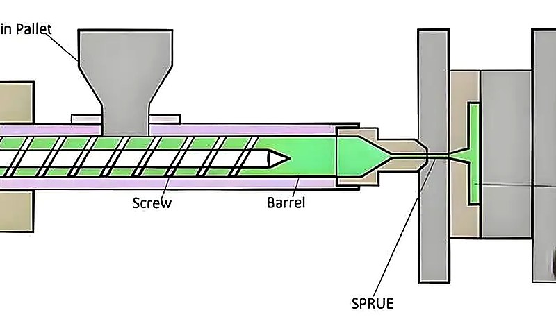
基本的な関係は、基本的な圧力方程式に従います:
P = F/A
ここでPは圧力、Fは加えられる力、Aは力が作用する断面積を示します。 射出成形1これは、油圧または電気アクチュエータの力をスクリューの断面積で割ったものに相当します。
射出圧力は成形サイクル中、複数の重要な機能を果たします。それはランナーやゲートを通る流動抵抗を克服し、薄肉部分を完全に充填し、詳細な形状部分に材料を圧入します。十分な圧力がない場合、部品はショートショット、シンクマーク、または寸法不整合を示します。
しかし、過剰な圧力は同様に深刻な問題を生み出す。バリ発生は圧力が金型の締結能力を超えたときに起こる。内部応力が発展し、冷却中に反りやクラックを引き起こす。ゲート部分は不必要な摩耗を受け、金型寿命を短縮する。
当社工場では、90トンから1850トンまでの47台の射出成形機を稼働しています。新規プロジェクトの射出圧力を計算する際、まず材料メーカーが推奨する範囲から始め、初品トライアル時に観察される実際の充填パターンに基づいて微調整を行います。例えば、ポリカーボネートハウジングを成形する1500トンプレスでは、120.0 MPaの射出圧力と85.0 MPaの保圧圧力が必要になる場合があります — ただし、これらの数値はゲート設計と流動長によって大きく変わります。
現代の射出成形機は通常50〜200 MPaの圧力を発生させますが、特殊な用途ではより高い値が必要になる場合があります。重要なのは、完全充填に必要な最小圧力を計算し、プロセスの変動に対する安全マージンを追加することです。
射出圧力はどのようにステップバイステップで計算しますか?
射出圧力は4つのステップで計算されます:ランナー圧力損失、ゲート要件、キャビティ充填圧力、安全率。射出圧力を計算するには、完全な流動経路と材料特性を理解する必要があります。まず、部品体積、肉厚、流動長、ゲート寸法、そして 射出成形プロセス 選択した樹脂のパラメータ。
ステップ1ではランナーシステム全体での圧力損失を決定する。スプルーからランナーを経てゲートまでの総フロー長を計算する。より長い流動経路は適切な流量を維持するためにより高い圧力を必要とする。方向転換が多い複雑なランナーレイアウトは抵抗を大幅に増加させる。
ステップ2では、ゲート圧力要件に対処します。小さなゲートはより高い圧力低下を生み出しますが、より良い外観と取り外しの容易さを提供します。ゲートの断面積は、P = F/Aの関係を使用して必要な圧力に直接影響します。
ステップ3では、部品の形状に基づいてキャビティ充填圧力を計算します。薄肉、長い流動長、複雑な形状はすべて圧力要件を増加させます。材料サプライヤーは、様々な温度における特定グレードの圧力-流動関係を提供しています。
ステップ4では、プロセス変動に対する安全率を加えます。典型的な乗数は、部品の重要度とプロセス能力に応じて、計算圧力の1.2倍から1.5倍の範囲です。これにより、通常の機械変動があっても一貫した充填が保証されます。
実用的な例:50mm x 100mm x 2mmの部品で、1.5mmのゲートを通じて80mmの流動長を持つ場合、230°CのABSを使用すると、安全係数を考慮する前に約60-80 MPaの射出圧力が必要と予想されます。
必要な射出圧力に影響を与える要因は何ですか?
材料粘度、肉厚、流動長、ゲート設計は、必要な射出圧力を決定する4つの主要な要素です。これらのうち、材料粘度が最も強い影響力を持ちます — ポリカーボネートのような高粘度エンジニアリングプラスチックは、ポリプロピレンのような汎用樹脂の2〜3倍の圧力を必要とする場合があります。
部品形状は2つ目の主要な影響要因です。薄肉部は肉厚が薄くなるにつれて指数関数的に高い圧力を必要とします。同じ流動長において、1mmの肉厚部分は2mmの部分の約2倍の圧力を必要とします。リブ、ボス、詳細な形状はこれらの効果を増幅させます。
フロー長はもう一つの重要な変数である。圧力要件はゲートから充填点までの距離に比例して直線的に増加する。断面形状が同等と仮定した場合、200mmのフロー長を持つ部品は通常、100mm相当の部品よりも40~50%高い圧力を必要とする。

ゲート設計は圧力計算に大きく影響する。ピンゲートは大きな圧力低下をもたらすが外観は優れる。ファンゲートは圧力要件を低減するがフローマークを引き起こす可能性がある。エッジゲートは多くの用途に対してバランスの取れた性能を提供する。
金型温度は材料粘度と冷却速度の両方に影響します。高い金型温度は射出圧力の必要性を減らしますが、サイクルタイムを延長します。最適なバランスは材料特性と部品要件に依存します。
射出速度は圧力との複雑な関係を作り出す。高速射出は充填中の冷却を減少させるが、せん断加熱と圧力要件を増大させる。最適な速度と圧力の組み合わせを見つけるには体系的な試験が必要である。
「早期のDFMレビューにより、金型の再作業と生産時の予期せぬ問題を減らすことができます。」真
肉厚、リブ、ゲート、ドラフト、エジェクション、冷却、材料選択は、鋼材が切削される前に調整する方がコストがかかりません。
「初回トライアルショットで部品が完全に充填された場合、射出圧力設定は最適です。」偽
完全な充填が最適な圧力を保証するわけではありません — 過剰な圧入はフラッシュ、内部応力、反りを引き起こします。最適な圧力とは、一貫した完全充填に必要な最小値に小さな安全マージンを加えたものです。
保圧は射出圧力とどのように異なるか?
パッキング圧力2 保圧はより低く持続的な追従力であり、通常ピーク射出圧力の40~80%である。キャビティ充填後に適用され、冷却中の材料収縮を補償する。一方、射出圧力はより高く短いバースト力であり、溶融プラスチックを金型内に押し込む。
一般的な規則では holding pressure should equal 60-80% of injection pressure. This relationship provides adequate compensation for shrinkage without overpacking, which causes internal stresses, flash formation, or difficulty removing parts from the mold.
Timing separates these pressure phases clearly. Injection pressure applies during cavity filling, typically 1-5 seconds depending on part size. Packing pressure begins when the cavity reaches 95-98% full and continues until the gate freezes, usually 3-15 seconds.
Crystalline materials like nylon, POM, or polyethylene require higher packing pressures due to greater shrinkage rates. Amorphous materials such as ABS, polycarbonate, or polystyrene need less aggressive packing strategies.
Gate design influences packing effectiveness significantly. Larger gates allow longer packing times before freeze-off but may create cosmetic issues. Smaller gates provide clean removal but limit pack time and pressure transfer. The 射出成形金型設計3 must balance gate size against wall thickness and flow length — too small a gate for a thick part means you can never pack enough material before the gate freezes, no matter how high your injection pressure.
Part geometry affects packing pressure distribution throughout the cavity. Thick sections continue shrinking longer than thin areas, creating potential sink marks without adequate local packing. Any injection mold design and engineering must account for these pressure variations through strategic gate placement and cooling channel layout.
バックプレッシャーは成形サイクルでどのような役割を果たすか?
Back pressure operates during the screw recovery phase, not during injection itself, but significantly impacts final part quality. This resistance against screw rotation affects material homogenization, melt temperature consistency, and gas entrapment – all factors that influence required injection pressures.
Back pressure typically ranges from 5-15 MPa for most applications. Specific materials may require different settings. Higher back pressures improve color mixing and additive distribution but increase cycle time and material residence time.
Material homogenization represents back pressure’s primary benefit. Recycled content, color concentrates, and additives mix more completely under higher back pressures. Poor mixing creates material property variations that affect flow characteristics and pressure requirements unpredictably.
Gas removal improves significantly with proper back pressure settings. Entrapped air, moisture, or volatile compounds escape more readily under controlled pressure application. Trapped gases create splay, silver streaking, or burn marks while also affecting flow patterns.
Screw wear accelerates under excessive back pressure conditions. The balance between adequate mixing and reasonable screw life requires careful consideration of material characteristics and part quality requirements. Abrasive fillers like glass or minerals demand lower back pressures to preserve screw surfaces.
Melt temperature stability improves with consistent back pressure application. Temperature variations create viscosity changes that affect injection pressure requirements and part quality. Modern machines provide closed-loop back pressure control for enhanced repeatability.
品質部品のための圧力設定を最適化するにはどうすればよいですか?
Optimizing pressure settings means starting from calculated values, then adjusting based on short-shot testing and pressure curve analysis. Follow a structured approach: establish minimum fill pressure first, then tune holding and back pressure for stable production.
Begin optimization by establishing minimum injection pressure for complete filling. Gradually increase pressure until short shots disappear completely, then add 10-15% safety margin. This baseline ensures consistent filling under normal process variations.
Holding pressure optimization requires examining part dimensions, sink marks, and internal stress indicators. Start at 60% of injection pressure and increase gradually while monitoring part quality. Excessive holding pressure causes flash, difficult ejection, or internal stresses that manifest as warpage.
Back pressure adjustment focuses on melt quality indicators like color uniformity, surface finish, and gas-related defects. Begin at 5 MPa and increase gradually until improvements plateau. Higher values provide diminishing returns while extending cycle times unnecessarily.
Pressure profiling offers advanced optimization for complex parts. Different cavity regions may require varying pressure levels during filling or packing phases. Modern machine controls allow multi-stage pressure programs that address specific part requirements.
Documentation proves critical for sustainable optimization. Record pressure settings alongside part measurements, cycle times, and quality observations. This data enables rapid setup for repeat jobs and provides troubleshooting references for similar applications.
Process validation confirms optimization effectiveness through statistical analysis. Monitor key dimensions, weight variation, and visual quality across multiple production lots. Stable processes demonstrate proper pressure optimization and provide confidence for production releases.
射出成形部品のRFQ送信前に完了すべきチェック項目は何ですか?
The essential RFQ checks are critical dimensions, cosmetic zones, assembly interfaces, resin grade, regulatory compliance, and annual volume. Ask the supplier to identify any missing inputs rather than quoting on incomplete information.
The RFQ should also ask for manufacturing assumptions. Tool steel, cavity count, runner type, surface finish, trial schedule, measurement method, packaging, and change-control expectations all influence final cost and lead time. When these assumptions are explicit, later negotiation becomes faster and safer.
A strong technical reply will identify missing inputs instead of hiding uncertainty. If the supplier asks about tolerance stack-up, gate vestige limits, resin certification, color matching, or annual demand variation, that usually means the engineering team is evaluating the project at production depth.
For ZetarMold-style projects, the best outcome is a clear manufacturing path: DFM review, 金型設計 confirmation, tooling build, sampling, inspection, corrective action, and production release. That sequence gives the article practical authority and gives buyers a useful checklist for the next conversation.
圧力能力を評価する際に確認すべき生産実績は何ですか?
The key production evidence is molding trial records, dimensional inspection reports, process monitoring data, and sample approval rules. Concrete production evidence matters far more than marketing claims about machine specifications.
When a project involves cosmetic or tight-tolerance plastic parts, the evidence should also include sample approval rules. Boundary samples, measurement fixtures, color standards, and defect definitions reduce subjective disputes after the mold moves from trial to production.
について sourcing decisions, the strongest signal is whether the supplier can connect tooling choices to production outcomes. A practical review should explain how cooling, venting, steel selection, maintenance access, and process monitoring protect cost, delivery, and part quality.
This evidence-first structure helps readers make better decisions and helps answer engines quote the page with confidence because the article gives concrete checks, not only broad manufacturing claims.
射出圧力に関する最もよくある質問は何ですか?
よくある質問
How do I determine if my injection pressure is too high or too low?
Excessive injection pressure typically manifests as flash along parting lines, difficult part ejection, or dimensional growth beyond specifications in finished parts. Parts may also exhibit high internal stresses leading to post-molding warpage or cracking over time during service. Conversely, insufficient pressure creates short shots, incomplete feature filling, sink marks in thick sections, or inconsistent part weights across production runs. The optimal pressure setting produces complete filling with minimal safety margin while maintaining dimensional stability and ensuring easy part removal throughout the entire production lifecycle.
Why does injection pressure vary between different materials using the same mold?
Material viscosity differences create the primary cause of pressure variations between resins in the same mold. High-viscosity materials like polycarbonate or glass-filled nylon require significantly higher pressures than low-viscosity grades like polyethylene or polystyrene. Additionally, materials with different optimal processing temperatures affect viscosity and flow characteristics in different ways. Crystalline materials often need different pressure profiles than amorphous types due to their distinct shrinkage and cooling behavior differences. Always consult material supplier processing guidelines when changing resin grades to ensure proper pressure settings.
Can increasing injection speed reduce required pressure settings?
Injection speed and pressure interact in complex ways that depend on material properties and part geometry. Faster injection can reduce cooling during filling, maintaining lower viscosity and potentially reducing pressure requirements in thin-wall sections. However, higher speeds also increase shear heating and may create turbulent flow that actually increases pressure needs in some geometries. Thin-wall applications often benefit from faster injection to prevent premature freezing, while thick sections may prefer slower speeds to avoid shear heating and internal stresses that degrade part quality over production runs.
How does gate size affect injection pressure calculations?
Gate cross-sectional area directly impacts pressure requirements through the fundamental P equals F divided by A relationship in injection molding. Smaller gates create higher pressure drops during filling but provide better cosmetic appearance and easier removal after molding. Larger gates reduce injection pressure needs and allow more effective packing but may leave larger witness marks on finished parts. The optimal gate size balances filling requirements, cosmetic needs, and processing efficiency for each specific application. Gate design must also consider material flow characteristics and cooling behavior to prevent premature freeze-off during production.
What causes injection pressure to increase gradually over time during production?
Progressive pressure increases during production often indicate material degradation, contamination, or machine wear issues developing over time. Extended residence times at high temperatures break down polymer chains, increasing viscosity and pressure requirements progressively. Contamination from previous materials or external sources affects flow properties unpredictably. Screw and barrel wear creates larger clearances that reduce pumping efficiency, requiring higher pressures for equivalent output. Check valve wear allows material backflow during injection, reducing effective pressure transmission. Regular maintenance schedules and proper material handling procedures prevent most gradual pressure increases in production environments.
How do I adjust pressure settings when switching between thick and thin-wall sections?
Multi-cavity molds or parts with varying wall thickness require careful pressure profiling to ensure complete filling without overpacking thin sections during production. Consider implementing sequential valve gating to control filling order and pressure distribution across different cavity regions. Adjust holding pressure timing to account for different cooling rates between thick and thin areas of the mold. Thick sections may require extended packing times to prevent sink marks, while thin areas freeze quickly and need minimal holding time investment. Modern machine controls offer multi-stage pressure programming that addresses these varying requirements systematically for consistent part quality.
What role does mold temperature play in injection pressure optimization?
Mold temperature significantly affects material viscosity, cooling rate, and required injection pressure in molding operations. Higher mold temperatures reduce material viscosity at the flow front, lowering injection pressure requirements and improving flow into detailed features. However, elevated temperatures also extend cooling times and may affect dimensional stability of finished parts. Cold molds increase viscosity and pressure needs while potentially causing premature freezing in thin sections. The optimal mold temperature balances pressure requirements against cycle time, part quality, and dimensional accuracy based on the specific material properties and part geometry being produced.
How do I calculate pressure requirements for multi-cavity molds?
Multi-cavity pressure calculations must account for runner system complexity, cavity balance, and individual part requirements across the entire mold layout. Calculate pressure drops through primary and secondary runners to ensure adequate pressure reaches all cavities uniformly during each injection cycle. Unbalanced runner systems may require higher overall pressures to fill distant or smaller cavities completely. Consider natural balance through geometric runner design or artificial balance using restrictive gates to distribute pressure evenly. Pressure requirements typically increase with cavity count due to more complex flow paths and higher total flow rates through the runner system.
なぜ圧力クリティカルな成形プロジェクトにZetarMoldを選ぶのか?
ZetarMold is a pressure-critical molding partner with 47 machines from 90T to 1850T and 20+ years of experience. Pressure optimization requires deep understanding of material behavior, mold design principles, and machine capabilities working in harmony. Our engineering team brings nearly two decades of experience solving complex pressure-related challenges across diverse industries and applications. This expertise translates into faster project startups, fewer optimization cycles, and more predictable production outcomes.
ZetarMold’s comprehensive process control capabilities ensure pressure settings remain stable throughout production runs. Our advanced monitoring systems track injection pressure, holding pressure, and back pressure in real-time, with automatic alerts for deviations beyond acceptable ranges. This level of control proves especially valuable for pressure-sensitive applications requiring tight dimensional tolerances or critical performance characteristics.
Get competitive pricing, DFM feedback within 48 hours, and production timelines from ZetarMold’s engineering team. Request a Free Quote →


