 コンテンツへスキップ

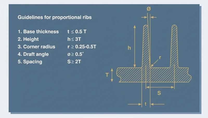
- ベントは薄いチャネルで、通常0.01〜0.02 mmの深さがあり、各キャビティのパーティングラインやインサート表面に研磨されています。ガスが逃げるのに十分な深さがあり、溶融プラスチックが漏れないように十分に浅くなっています。複雑な形状では、シミュレーションで特定された特定の場所に配置された多孔質鋼インサートやベントピンを通じて追加のベントが提供される場合があります。
- Runner balancing and symmetrical cavity layouts are essential to ensure every cavity fills uniformly.
- Advanced cooling strategies—especially conformal channels—can reduce cycle time by up to 30%.
- Proper validation through short-shot analysis and cavity pressure monitoring prevents costly production defects.
- Choosing the right tooling material and surface coating extends mold life to millions of cycles.
In modern plastic manufacturing, designing multi-cavity molds is one of the most effective ways to scale production without proportionally increasing costs. A multi-cavity mold contains two or more identical cavities, allowing an 射出成形 machine to produce several parts in a single cycle. This approach is indispensable for industries that require millions of identical components—think bottle caps, medical syringes, electronic connectors, and automotive clips. The payoff is significant: higher throughput, lower per-part cost, and improved consistency across large production runs.
However, the benefits come with increased engineering complexity. Each additional cavity introduces new variables—flow resistance, thermal distribution, ejection timing—that must be precisely managed. This guide walks through every critical aspect of multi-cavity injection mold design, from fundamental principles and Runner Balancing1 to cooling strategies, validation methods, and cost analysis.
What Is a Multi-Cavity Mold and How Does It Work?
A multi-cavity mold is a specialized tool used in plastic injection manufacturing that contains multiple identical cavities within a single mold base. When the machine injects molten polymer into the mold, the material flows through a runner system and simultaneously fills every cavity, producing several finished parts in one cycle. The number of cavities can range from as few as two to over sixty-four, depending on part size, machine tonnage, and production requirements.
The core principle is simple: instead of molding one part per cycle and waiting for the next shot, you mold many. This dramatically increases effective output. For example, a machine running a 16-cavity mold with a 22-second cycle can produce over 2,500 parts per hour, compared to roughly 160 parts per hour with a single-cavity mold running a slightly shorter 18-second cycle.
There is an important distinction between multi-cavity molds and family molds. In a multi-cavity mold, every cavity produces the same part, ensuring uniform flow characteristics and quality. In a family mold, different cavities produce different parts, which complicates flow balancing because each cavity has a unique volume and geometry. For consistent, high-quality output, true multi-cavity designs are strongly preferred.
The decision to use a multi-cavity mold should be driven by a careful analysis of annual production volume, part complexity, and available press capacity. When production volumes justify the additional tooling investment, the return on investment is typically realized within the first production run. If you are comparing vendors or planning procurement, our 射出成形調達ガイド covers RFQ preparation, supplier qualification, and commercial risk assessment in detail.
In our Shanghai factory, our team runs 47 injection molding machines from 90T to 1850T, which supports multi-cavity tools from low-volume pilot runs to high-volume production molds. That tonnage range matters because cavity count changes shot size, clamp-force demand, and validation risk.
Why Should You Choose a Multi-Cavity Mold for High-Volume Production?
This section is about choose a multi-cavity mold for high-volume production and its impact on cost, quality, timing, or sourcing risk. The primary driver for choosing a multi-cavity mold is economic: spreading the fixed cost of machine time, energy, and labor across many more parts per cycle significantly reduces the cost per unit. While the initial tooling investment is higher—often three to five times the cost of a single-cavity mold—the per-part savings become substantial once production volumes exceed the break-even threshold, typically around 500,000 to 1,000,000 parts.
Beyond cost, multi-cavity molds improve dimensional consistency. Because all parts are molded under the same machine settings, temperature, and pressure profile, the variation between parts from different cavities is typically smaller than the variation you would see between parts produced on different machines or in different runs. This is especially important in regulated industries such as medical devices and automotive, where tight tolerances are mandatory.
| ファクター | 単一キャビティ金型 | 8-Cavity Mold | 16キャビティ金型 |
|---|---|---|---|
| Approximate Tooling Cost | $8,000–$15,000 | $25,000–$45,000 | $45,000–$80,000 |
| サイクルタイム | 18 sec | 22秒 | 24 sec |
| Parts per Hour | ~200 | ~1,300 | ~2,400 |
| Cost per Part (at 1M units) | $0.12 | $0.05 | $0.035 |
| Break-Even Volume | - | ~400,000 parts | ~600,000 parts |
The table above illustrates a key insight: cycle time increases only slightly as you add cavities, while output scales almost linearly. The result is a dramatic reduction in per-part cost that accelerates return on investment for any high-volume project.
How Do You Achieve Runner Balance in Multi-Cavity Molds?
Runner balancing is arguably the most critical engineering challenge in multi-cavity mold design. When molten plastic enters the mold, it must reach every cavity at the same time, at the same pressure, and with the same temperature profile. If one cavity fills before another, the result is over-packing, flash, short shots, or dimensional variation. The same logic applies to ランナーとゲートのデザイン, where small geometry differences can turn into repeatable production defects.
The runner system is the network of channels that carries molten polymer from the machine nozzle through the sprue and into each cavity. In a naturally balanced runner, every cavity is equidistant from the sprue, meaning the flow path length and resistance are identical. This is achieved through symmetrical layouts such as radial (cavities arranged in a circle around the sprue) or H-pattern configurations.
When natural balancing is impractical—often due to mold size constraints or part geometry—engineers use artificially balanced runners, adjusting the diameter and length of individual runner branches to equalize flow resistance. This requires precise simulation using Moldflow or similar software to model pressure drops and filling patterns before the steel is ever cut.
“A naturally balanced runner layout ensures that every cavity has an identical flow path length from the sprue.”真
In a naturally balanced system, cavities are arranged symmetrically—such as in an H-pattern—so the distance and resistance from the sprue to each cavity are equal, promoting simultaneous fill without artificial adjustments.
“Increasing runner diameter always improves cavity fill balance in a multi-cavity mold.”偽
While larger runners reduce pressure drop, they also increase material waste and can cause excessive packing in cavities closer to the sprue. Balance is achieved through precise sizing, not simply by making runners larger.
Hot runner systems are strongly recommended for multi-cavity molds with eight or more cavities. A hot runner uses heated manifolds to keep the polymer molten inside the channel, eliminating the cold runner waste that would otherwise need to be reground or discarded. Hot runners also provide more consistent temperature control at each gate, improving fill uniformity across all cavities.

What Role Does Cooling Play in Multi-Cavity Mold Performance?
Cooling accounts for approximately 70% of the total injection molding cycle time, making it the single largest factor in determining throughput. In a multi-cavity mold, the cooling challenge is amplified because every cavity must solidify at the same rate. If one cavity cools faster than another, parts will have different shrinkage, warpage, and dimensional accuracy.
Traditional drilled cooling channels follow straight paths and cannot closely follow the contours of complex part geometries. This creates hot spots—areas where heat removal is slower—leading to uneven cooling and part defects. コンフォーマル冷却2 channels, made possible by metal additive manufacturing, follow the exact shape of the cavity surface and provide uniform heat extraction across the entire mold. Studies have demonstrated that conformal cooling can reduce cycle time by 20–40% compared to conventional drilled channels.
Effective cooling design in a multi-cavity mold also requires parallel cooling circuits rather than series circuits. In a series circuit, coolant absorbs heat from the first cavity and arrives at the last cavity at a higher temperature, creating a thermal gradient. Parallel circuits deliver coolant at the same inlet temperature to every cavity, ensuring uniform cooling performance across the entire mold.
Thermal simulation software such as Moldex3D or Autodesk Moldflow allows engineers to visualize temperature distribution across the mold and optimize channel placement before manufacturing. Proper baffle and bubbler placement within each cavity ensures that even thick-wall sections receive adequate cooling. For high-cavity-count molds, investing in thorough thermal simulation during the design phase can prevent weeks of troubleshooting during production qualification.
“Parallel cooling circuits provide more uniform temperature distribution across all cavities compared to series circuits.”真
Parallel circuits deliver coolant at the same inlet temperature to every cavity simultaneously. In series circuits, coolant heats up progressively as it passes through successive cavities, creating thermal gradients that cause inconsistent part quality.
“Using softer mold steel like P20 is always the best choice for multi-cavity molds because it reduces initial tooling cost.”偽
While P20 reduces upfront cost, it wears faster under high-volume production. For molds expected to run millions of cycles, harder steels like H13 or S136 provide better long-term value by maintaining cavity dimensions and surface finish over a much longer service life.
How Do Venting and Ejection Systems Affect Part Quality?
This section is about venting and ejection systems affect part quality and its impact on cost, quality, timing, or sourcing risk. When molten plastic fills a cavity, it displaces air and any moisture or gases from the polymer itself. If this trapped gas cannot escape quickly enough, it compresses, heats up, and causes diesel burns—small charred spots on the part surface known as burn marks. In multi-cavity molds, venting must be carefully engineered at every cavity because the rapid filling of multiple cavities simultaneously generates a large volume of displaced gas in a very short time. Poor venting is one of the recurring causes behind 射出成形の欠陥 in high-cavity tools.
Vents are thin channels, typically 0.01–0.02 mm deep, ground into the parting line or insert surfaces of each cavity. They are deep enough to allow gas to escape but shallow enough to prevent molten plastic from leaking through. In complex geometries, additional venting may be provided through porous steel inserts or vent pins placed at specific locations identified by simulation.
キャビティ圧力モニタリング:

When Should You Use a Hot Runner vs. Cold Runner System?
The choice between hot runner and cold runner systems has a significant impact on material waste, cycle time, and part quality in multi-cavity molds. A cold runner system is the simpler and less expensive option: molten plastic flows through unheated channels and solidifies along with the parts. The solidified runner must then be separated from the parts and either reground or discarded. For low-cavity molds (two to four cavities) running commodity materials, cold runners can be cost-effective.
However, as cavity count increases, cold runner waste becomes a serious economic concern. In a 16-cavity mold, the cold runner may represent 20–40% of the total shot weight, meaning a significant portion of every cycle is wasted material. A Hot Runner System3 eliminates this waste by maintaining the polymer in a molten state within heated channels, so no solidified runner is produced.
Hot runners also offer superior gate control. Valve gates can be opened and closed sequentially, allowing engineers to fine-tune the filling sequence and reduce weld-line visibility. Thermal gates provide clean separation without gate vestige, improving part aesthetics. For engineering-grade resins that are sensitive to thermal degradation, hot runners with individually controlled zones ensure each cavity receives material at the optimal temperature.
The trade-off is cost and maintenance complexity. A hot runner system adds $5,000–$20,000 or more to the tooling cost and requires periodic maintenance of heaters, thermocouples, and manifold seals. For production runs under 100,000 parts, the material savings may not justify the additional investment. The following table summarizes the key differences:
| 特徴 | Cold Runner | ホットランナー |
|---|---|---|
| Initial Tooling Cost | Lower ($2,000–$5,000) | Higher ($7,000–$20,000+) |
| 廃棄物 | High (runner solidifies) | Minimal (no solidified runner) |
| Cycle Time Impact | Neutral | Slightly faster (no runner cooling) |
| Gate Quality | May leave vestige | Clean, controlled separation |
| メンテナンス | Simple | Requires heater/thermocouple service |
| 最適 | Low-cavity, short runs | High-cavity, long production runs |
What Materials and Coatings Maximize Mold Longevity?
The choice of mold steel directly impacts tool life, part surface finish, and maintenance frequency. For multi-cavity molds running millions of cycles, material selection is not an area to economize. The most commonly used steels in high-production molds include P20 (pre-hardened to 30–36 HRC for moderate volume), H13 (hot-work steel hardened to 44–52 HRC for high-volume, high-temperature applications), and S136 (stainless steel with excellent polishability for optical and medical parts).
Surface coatings further extend tool life by reducing friction, preventing corrosion, and improving polymer release. Diamond-Like Carbon (DLC) coatings provide exceptional hardness and low friction, reducing wear on high-contact surfaces such as cores and slides. Titanium Nitride (TiN) and Chromium Nitride (CrN) coatings offer good corrosion resistance and are widely used in molds processing glass-filled or corrosive polymers.
Regular maintenance is essential to preserve mold performance over time. Cooling channels should be flushed and descaled periodically to maintain heat transfer efficiency. Ejector pins and guide bushings should be inspected for wear and replaced before they begin to score the mold surfaces. A well-maintained multi-cavity mold can reliably produce 5–10 million parts or more over its service life.
How Do You Validate and Balance a Multi-Cavity Mold Before Production?
Validation is the critical bridge between mold design and production readiness. Even the most carefully designed mold can exhibit unexpected behavior when it encounters real-world processing conditions. A structured validation process identifies and corrects issues before they reach full-scale manufacturing, saving time and preventing costly scrap.
The first validation step is short-shot analysis. By intentionally injecting less than the full shot volume, engineers can observe the filling pattern of each cavity. In a perfectly balanced mold, every cavity should show the same degree of partial fill. Any discrepancy indicates a flow imbalance that must be corrected through runner adjustments or gate size modifications.
Cavity pressure monitoring provides quantitative data on fill uniformity. Pressure sensors installed in each cavity record the filling profile in real time, allowing engineers to compare peak pressures, fill times, and packing behavior across cavities. This data is invaluable for fine-tuning process parameters and verifying that every cavity produces parts within specification.
Finally, dimensional capability studies (Cp/Cpk) confirm that parts from all cavities meet the required tolerances. A minimum Cpk of 1.33 is typically required for production approval, indicating that the process is capable of producing parts well within specification limits. Parts from each cavity are measured using coordinate measuring machines (CMMs) or optical inspection systems, and the data is analyzed to identify any cavity-specific deviations that require correction.
With 20+ years of injection molding and tooling experience, our engineers validate multi-cavity molds with short-shot studies, cavity-balance checks, dimensional sampling, and process-window testing before production approval. Machines from 90T to 1850T give our team room to match the tool to the right press instead of forcing a high-cavity mold into marginal clamp capacity.
What Questions Do Buyers Ask About Designing Multi-Cavity Molds?
よくある質問
What Is the Ideal Number of Cavities for a Multi-Cavity Mold?
There is no universal ideal cavity count. The right number depends on part size, projected annual volume, material flow behavior, available press tonnage, and the tolerance risk of the part. For many production programs, 4 to 32 cavities is the practical range. Small caps, seals, and connectors can go higher because shot size and clamp force stay manageable. Larger parts usually need fewer cavities. The safe method is to compare tooling cost, cycle time, scrap risk, and demand forecast before locking the cavity count.
How Much More Does a Multi-Cavity Mold Cost Compared to a Single-Cavity Mold?
A multi-cavity mold costs more than a single-cavity mold because the tool needs more cavities, gates, runners, cooling circuits, ejection components, and validation work. An 8-cavity mold may cost three to four times more than a single-cavity tool, while a 16-cavity mold can cost five to seven times more. That does not automatically make it expensive per part. If annual demand is high, the extra tooling cost is spread across more parts, often reducing unit cost by 50 to 70 percent.
Can a Multi-Cavity Mold Produce Different Parts Simultaneously?
はい、一つの金型で異なる部品を同時に成形することは可能ですが、それは通常ファミリー金型と呼ばれ、真のマルチキャビティ金型ではありません。ファミリー金型は、一つの組立品で一緒に使用される複数の少量部品に有効です。リスクは、各部品の体積、肉厚、必要な圧力が異なるため、流動バランスが崩れることです。一方のキャビティが過充填になる一方で、他方ではショートショットが発生する可能性があります。寸法の一貫性が重要な大量生産では、同一キャビティを持つ専用のマルチキャビティ金型の方が通常、より安全で検証も容易です。
マルチキャビティ金型においてランナーバランスがなぜそれほど重要ですか?
ランナーバランスが重要なのは、すべてのキャビティがほぼ同じ時間、圧力、温度で充填されなければならないためです。スプルーに近いキャビティが先に充填されると、過充填やフラッシュが発生する可能性があります。遠くのキャビティはショートショットしたり、弱い溶着線が現れたりする可能性があります。その結果、寸法が不均一になり、不良率が高くなります。バランスの取れたランナーレイアウトは、等しい流動長、制御されたランナー径、シミュレーションデータを用いて、キャビティ間の抵抗を均一に保ちます。高キャビティ金型では、この作業は鋼材加工前に完了させるべきであり、試作中に修正するものではありません。
マルチキャビティ金型の製作にはどのくらい時間がかかりますか?
マルチキャビティ金型のリードタイムは通常6週間から16週間の範囲です。部品形状が単純で材料の挙動が熟知されている場合、シンプルな4キャビティのコールドランナー金型であれば6~8週間で完成する可能性があります。ホットランナー、スライド、厳しい公差、コンフォーマル冷却を備えた32キャビティ金型では12~16週間かかることがあります。スケジュール上の最大のリスクは、設計変更の遅れ、樹脂グレードの未確定、DFM承認の遅延、T1試作での修正の繰り返しです。早期の製造性レビューはこれらの遅延を減らし、量産開始日を守ります。
マルチキャビティ金型にはどのようなメンテナンスが必要ですか?
マルチキャビティ金型は、キャビティ間のわずかな摩耗差が時間とともに品質変動につながるため、定期的な予防保全が必要です。通常のメンテナンスには、キャビティ表面の清掃、冷却水路の洗浄、ベントの確認、スライドの潤滑、エジェクタピンの点検、ホットランナーヒーターや熱電対のテストが含まれます。多くの工場では、生産金型を10万~20万ショットごとにメンテナンスし、摩耗性や腐食性のある材料ではより短い間隔で実施します。重要なのは、金型ごとのショット数を記録し、キャビティ固有の問題を記録することであり、これにより一つの弱いキャビティが知らぬ間に出力品質を損なうことを防ぎます。
マルチキャビティ金型に適した射出成形パートナーをどのように選びますか?
類似のキャビティ数、材料、公差、検証要件を以前に扱った経験があるかどうかを確認してパートナーを選定してください。マルチキャビティ金型の事例、射出成形機のトン数範囲、社内金型設計能力、キャビティバランスの検証方法について尋ねましょう。信頼できるサプライヤーは、ショートショット解析、キャビティごとの寸法サンプリング、Cpk目標、冷却チェック、メンテナンス計画について説明できるはずです。見積もられた金型価格だけで判断しないでください。キャビティ間でバランスを維持できない安価な金型は、不良品やダウンタイムによりかえって高くつきます。
マルチキャビティ金型設計ではどのようなシミュレーションツールが使用されますか?
マルチキャビティ金型設計で一般的に使用されるシミュレーションツールには、Autodesk Moldflow、Moldex3D、SolidWorks Plasticsなどがあります。これらのソフトウェアは、金型加工前に、充填圧力、ランナーバランス、溶着線位置、冷却効率、収縮、そりをモデル化します。シミュレーションは金型試作の代わりにはなりませんが、ランナーの不均衡、不適切なゲート位置、肉厚部分周辺のホットスポットなどの明らかなミスを防ぎます。高キャビティ金型の場合、シミュレーション結果は、金型レイアウト、冷却回路設計、想定される射出成形機能力と共に、鋼材発注前にレビューされるべきです。
How Can You Optimize Production with Multi-Cavity Molds?
Designing multi-cavity molds is a strategic investment that pays dividends through higher output, lower per-part costs, and improved consistency. Whether you need a 4-cavity mold for mid-volume production or a 32-cavity mold for high-volume manufacturing, the engineering principles covered in this guide—runner balancing, cooling optimization, venting design, and thorough validation—are the foundation of success.
ZetarMoldは20年以上の金型設計・製造経験を持ち、90トンから1850トンまでの47台の射出成形機でサポートされています。コンセプトから生産検証まで、すべての 射出成形金型 プロジェクトは、信頼性、キャビティバランス、生産効率のために設計されています。
Get a free quote and DFM review for your multi-cavity mold project today. ZetarMoldのエンジニアリングチームにご連絡いただき、要件についてご相談ください。最適化された金型設計がどのように生産コストを変革できるかをご確認いただけます。
-
Runner Balancing: Runner Balancing refers to the process of adjusting runner dimensions so that every cavity in a multi-cavity mold fills at the same time and pressure, as defined by flow simulation standards. ↩
-
Conformal Cooling: コンフォーマル冷却とは、通常金属積層造形を用いて製造され、金型キャビティの形状に沿って配置される冷却水路を指し、直線的に穴あけされた水路よりも均一な熱除去を提供します。 ↩
-
ホットランナーシステム: Hot Runner System refers to a temperature-controlled manifold that keeps plastic in a molten state inside the runner, eliminating runner waste and improving fill consistency across cavities. ↩


