 コンテンツへスキップ

What Are Injection Molded Ribs and Bosses?
射出成形リブと ボス1は、このセクションで説明されている主なカテゴリーまたはオプションです。効果的なプラスチック部品を設計するには、エンジニアは構造補強と組立機能を区別する必要があります。リブ、ボス、ガセット、肉厚遷移はCAD上では小さく見えますが、剛性、シンクリスク、ネジ強度、冷却バランス、金型アクセスを決定します。ベンダーを比較する場合は、これらのチェックを当社の injection molding supplier sourcing guide 金型承認前。この DFM2 ステップは、後の金型変更を防ぐのに役立ちます。
- リブは嵩を増さずに剛性を高めます;ボスはネジ、インサート、および位置合わせを可能にします。
- シンクマーク、ボイド、および反りを避けるため、両方の特徴は公称肉厚の40〜60%以内に収める必要があります。
- 独立したボスは、トルク荷重を周囲の壁に分散させるためにガセット(支持リブ)接続が必要です。
- 金型加工前にリブとボスの形状を徹底したDFMレビューすることで、コストのかかる金型修正を防ぎます。
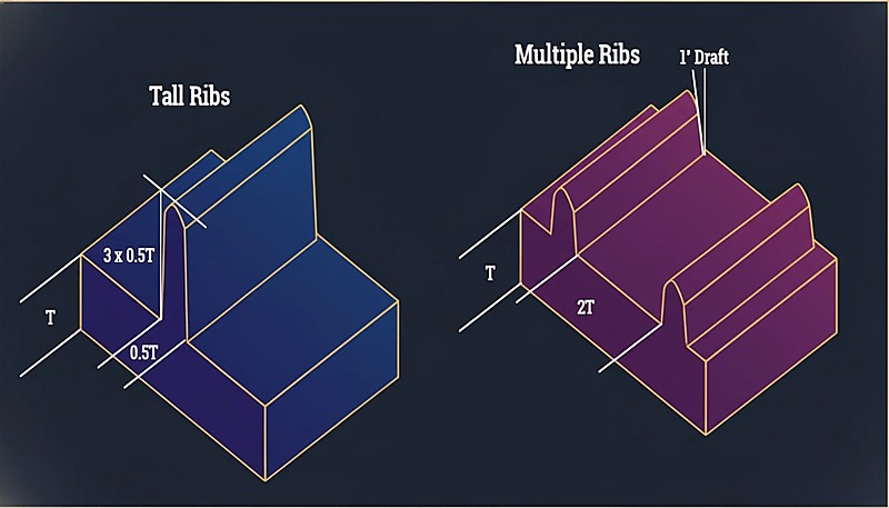
肋骨 は、公称壁から延びる薄い壁状の突起です。その主な機能は、全体の肉厚を増やすことなく部品の剛性を高めることです。平らなパネル、カバー、筐体、および部品により高い剛性が必要な荷重支持領域の背面で有用です。適切なリブ設計は、 リブの厚さ3高さ、勾配、根元半径、間隔を調整し、反対面にシンクマークを作らずに強度を追加するように設計します。より広範な設計の文脈については、当社の 射出成形金型設計 guide.
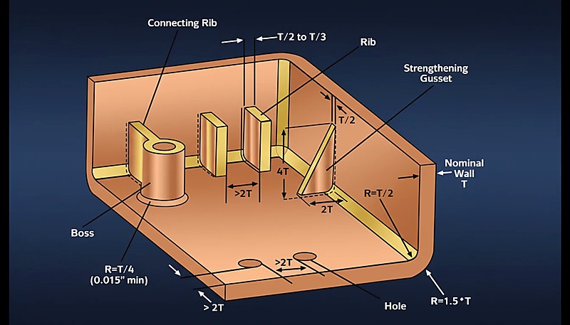
ボス は円筒状の突起で、通常は中空になっており、ネジ、インサート、位置決めピン、または組立機能をサポートするように設計されています。ボスはネジやインサートの周囲に十分な肉厚を持たせながら、基部での過度な肉盛りを避ける必要があります。強固なボス設計では、荷重を近接する壁に伝達するためにリブやガセットが使用されることが多いです。これによりネジ取り付け時のクラックを防止し、外観面周辺の歪みを軽減します。これらの詳細はより広範な 射出成形 プロセスだ。
“Bosses that are not connected to the sidewall should always be supported by gussets (support ribs) at the base.”真
Standalone bosses are prone to bending or breaking under torque; gussets distribute the load into the floor of the part and improve material flow.
“It is acceptable to design a boss with the same wall thickness as the main housing to ensure maximum screw retention strength.”偽
Making boss walls equal to the nominal wall creates a massive thick section at the base, guaranteeing sink marks and voids. Boss walls should be roughly 60% of the nominal wall.
主要な設計パラメータにおいて、リブとボスはどのように比較されますか?
機能は異なりますが、両方の幾何学的ルールは均一な肉厚、安定した冷却、予測可能な充填に基づいています。ボスはしばしばリブ支持を必要とし、リブはボス基部付近の局所的な流動、冷却、および取り出し挙動を変化させる可能性があるため、リブとボスは一緒にレビューされるべきです。
| Feature Parameter | Rib Design Rules | Boss Design Rules |
|---|---|---|
| Primary Function | Structural Stiffness, Warpage Control | Mechanical Assembly, Alignment |
| Geometry | Linear, Plate-like | Cylindrical (Tubular) |
| ベース厚 | 40% – 60% of Nominal Wall (t) | 60% of Nominal Wall (t) |
| Height Constraint | ≤ 3 × Nominal Wall (t) | ≤ 2.5 × Outer Diameter (typical) |
| ドラフト角度 | 0.5° – 1.5° per side | 0.5° exterior; 0.25° interior (to grip screws) |
| Spacing | ≥ 2 × Nominal Wall (t) between ribs | ≥ 2 × Nominal Wall (t) from sidewalls |
| Common Defect | Sink Marks (surface depression) | 溶着ライン 2(構造的弱点) |
What Are the Advantages and Disadvantages?
リブの利点は剛性、材料効率、冷却の速さであり、ボスの利点は締結、位置決め、インサート支持です。デメリットは、両方の特徴が局所的な肉厚変化を生み出すため、不適切な形状はシンクマーク、ガス巻き込み、クラック、または冷却時間の延長を引き起こす可能性があることです。ボスはリブ支持を必要とし、リブは化粧面や局所的な流動経路に影響を与える可能性があるため、両方の特徴を一緒にレビューしてください。
Ribs: Structural Reinforcement
| リブの利点 | リブのデメリット |
|---|---|
| 材料効率:厚い肉厚と比較して、最小限の樹脂使用量で部品強度を大幅に向上させます。 | 化粧面リスク:リブと壁の交差部は、クラスA面におけるシンクマークの主要な発生箇所です。 |
| サイクル速度:薄いリブは冷却が速く、サイクルタイムを短く保ちます。 | ベント:深いリブはガスを閉じ込め(ディーゼル効果)、適切にベントされないと焼けの原因となります。 |
| 流動先導:金型の薄肉部の充填を助けるフローランナーとして機能できます。 | 離型の問題:リブの勾配が不十分だと、部品が金型に張り付いたり、引きずり跡が発生したりします。 |
Bosses: Assembly Interface
| ボスの利点 | ボスのデメリット |
|---|---|
| 二次加工なしでネジ締結、圧入インサート、位置合わせを可能にします。 | 厚い基部は、化粧面に目立つシンクマークを引き起こす可能性があります。 |
| 金型に直接組み込まれるため、組立穴のための成形後加工は不要です。 | 不適切な内径や肉厚は、ネジ取り付け時にボスが割れる原因となります。 |
| ガセットやリブと組み合わせて、ファスナーの荷重を周囲の構造に分散させることができます。 | きれいに離型し、引っかかりを避けるためには、慎重な勾配、半径、中空化が必要です。 |
“Connecting a boss to a sidewall using a thin rib eliminates thick material sections while maintaining stability.”真
This technique ties the boss to the structure for strength without creating a heavy cross-section that would cause sink marks.
“Blind bosses (bosses that do not pass through the part) do not require draft angles on the inside diameter.”偽
All vertical steel surfaces in injection molding require draft for ejection. A zero-draft core pin creates a vacuum and friction, causing the pin to seize or break during ejection.
When Should You Apply Each Feature?
リブは厚い肉厚なしで剛性を確保するのに最適であり、ボスはネジ、インサート、ピン、位置決めに最適です。部品が曲げ抵抗、平坦性、または荷重分散を必要とする場合はリブを使用します。製品構造が締結点や位置決め基準を必要とする場合はボスを使用します。両方の機能が重なる場合は、ベース周りに固形プラスチックを追加する代わりに、薄いガセットでボスを接続します。
Application Scenarios for Ribs
大きな平坦面: 自動車ドアパネル、家電筐体、薄いカバーなどでオイル缶現象を防ぐためにリブを使用します。リブ基部を制御し、化粧面にシンク、リードスルー、または流動遅れが現れないようにします。これは外表面がテクスチャ加工、塗装されている場合、または顧客の目に触れる場合に重要です。
荷重支持フロア: 部品が曲げに耐える必要があるトレイ、容器、ブラケット、パレットの下にリブを追加します。リブの方向は、CADモデルの空きスペースを埋めるだけでなく、荷重経路に沿うようにします。設計者は、リブの高さと間隔が安定した充填と金型からの離型を可能にすることを確認する必要があります。
衝撃ゾーン: リブはバンパーカバーや保護ケース、工具ハウジングの背面に配置し、衝撃エネルギーを分散させます。孤立した厚肉交差部は応力集中や成形不良を引き起こす可能性があるため避けてください。衝撃部品については、リブの連続性、半径、材料の靭性を総合的に検討する必要があります。
反り補正: 剛性と冷却収縮を均等化するために、バランスの取れたリブパターンを使用します。交差リブは役立ちますが、安定した充填と離型を可能にする勾配、半径、間隔の設計は依然として必要です。バランスの悪いリブは、平坦な面を改善するどころか悪化させる可能性があります。
Application Scenarios for Bosses
PCB取り付け: ボスは、タップ切りネジやインサートを使用して、電子機器筐体内のプリント基板を固定します。ボスの高さ、ガイド穴、補強リブは、ネジ荷重、組立トルク、耐用年数に合わせて設計し、繰り返し使用後も基板が安定した状態を保つようにします。
筐体組立: Bosses help mate the top and bottom halves of clamshell housings such as controllers, chargers, and remote controls. Good layout keeps screw force away from thin cosmetic walls and leaves enough room for core pins, ejectors, and cooling.
Insert installation: Bosses can hold brass threaded inserts for parts that require repeated disassembly, such as battery compartments or service covers. The boss needs enough material for heat staking or ultrasonic insertion, but excessive thickness can still cause sink and long cooling.
Alignment: Non-threaded bosses or pins help mating parts line up before fastening. This reduces assembly friction and prevents screws from being used as alignment tools, which can crack plastic. Clearance, draft, and tolerance stack-up should be checked with the mating part.
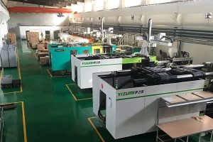
In our Shanghai factory, our engineers with 20+ years of experience use 47 injection molding machines (90T-1850T) to review rib thickness ratios, boss support structures, and sink-mark risk before mold steel is cut. We recommend documenting each rib and boss correction in the DFM report so buyers can compare geometry risk, not just price.
How Do You Integrate Ribs and Bosses Step by Step?
Rib and boss integration is a staged DFM workflow. First locate every screw, insert, and alignment boss, then dimension each boss from fastener data, place ribs along the bending direction, connect unsupported bosses to walls with gussets, and finally review intersections for sink, draft, venting, ejection, and tool-access risk before steel cutting.
Identify assembly points first.
Determine where screws, inserts, PCB standoffs, or locating pins are needed. Place bosses at those coordinates, then check whether the boss is too close to a corner, shutoff, ejector, or cosmetic wall that could limit cooling or tool access. Mark high-load locations before adding ribs.
Dimension the bosses.
Set the inner diameter from the fastener or insert supplier data, then size the outer diameter and boss wall to avoid cracking and sink. Check screw engagement depth, pilot hole tolerance, draft, and whether the boss needs coring at the base. Confirm the screw torque range before T1.
“Rib and boss intersections need DFM review before tooling.”真
The highest-risk area is often where a boss base, rib root, cosmetic wall, and screw load meet. Checking this intersection before steel cutting reduces sink, cracking, and rework.
“A thicker rib always improves a plastic part.”偽
A thicker rib can increase sink marks, cooling imbalance, and warpage. Multiple moderate ribs with correct draft and spacing are usually safer than one heavy rib.
Determine structural needs second.
Analyze where the part will flex or carry load. Place ribs perpendicular to the bending direction and keep rib root thickness near the material-safe range. Use multiple moderate ribs instead of one thick rib when cosmetic risk is high. Check flow length and gate location at the same time.
Integrate and support with gussets.
A standalone boss is weak. Connect it to the nearest wall or floor using thin gussets or ribs. Avoid filling the full gap with solid plastic because that creates thick sections, slow cooling, and visible sink on the opposite surface. Use rib support only where it improves load transfer.
Manage intersections and mold access.
Where ribs meet bosses or walls, add radii of at least 0.25 times wall thickness when the material and tool design allow it. Confirm draft, venting, polishing access, ejection direction, and whether lifters or slides are required. If you need DFM feedback on rib and boss geometry, request a quote from ZetarMold before tool cutting.
What Questions Do Buyers Ask About Rib and Boss Design?
-
boss: A boss is a raised feature commonly used for screws, inserts, fastening, or locating functions in molded parts. ↩
-
DFM: DFM refers to review checks whether a plastic part design can be molded reliably before tooling investment. ↩
-
rib thickness: rib thickness refers to is usually limited as a percentage of nominal wall thickness to reduce sink and uneven cooling. ↩
よくある質問
プラスチック設計において、リブとボスの違いは何ですか?
Ribs reinforce plastic walls, covers, and floors so a part becomes stiffer without making the entire wall thicker. Bosses support screws, threaded inserts, locating pins, or assembly features. Ribs mainly solve structural stiffness problems, while bosses mainly solve fastening and alignment problems. Both need wall-thickness control because thick rib roots or boss bases can cause sink, voids, warpage, and long cooling cycles. In a good design review, the supplier checks how the two features interact instead of judging each feature alone.
リブとボスはどちらを先に設計すべきですか?
Bosses are often placed first when screw locations, insert positions, PCB supports, or assembly constraints are fixed by the product architecture. Ribs are then added to support those bosses, connect load paths, and stiffen nearby surfaces. If the part is mostly structural, rib layout may start earlier. The safest workflow is to define assembly loads, locate bosses, add rib support, then review thickness, draft, radius, and mold access. This order reduces rework when the tooling engineer starts steel design and reviews cooling access.
リブの厚さは、主壁と比較してどの程度であるべきですか?
A practical starting point is to keep rib thickness around 50% to 60% of the nominal wall thickness for many injection molded plastics. Thicker ribs can create sink marks because the rib root cools more slowly than the surrounding wall. The final value depends on resin shrinkage, surface requirements, tool steel condition, and flow length, so DFM should confirm the ratio against the selected material. If the outer face is cosmetic, conservative rib sizing is usually safer for production and later quality approval.
なぜボスはネジ取り付け時に割れるのですか?
Bosses often crack when the inner diameter is too small, the outer diameter is too thin, the screw creates too much hoop stress, or the boss lacks rib or gusset support. Brittle materials, sharp internal corners, and poor insert installation temperature can make the problem worse. A better design uses the correct pilot hole, enough wall around the screw, rounded transitions, proper draft, and support ribs that spread load. Trial assembly should confirm torque, pull-out strength, and repeatability before approval.
バイヤーはサプライヤーとどのようにリブとボスの設計をレビューすべきですか?
Buyers should ask the supplier to review rib thickness, boss diameter, screw engagement, insert method, sink-mark risk, draft, texture, ejection marks, and mold steel access before tool cutting. They should provide assembly loads, screw type, material grade, tolerance requirements, and cosmetic surface priorities. A capable supplier should return DFM comments explaining which ribs or bosses need adjustment, not just a price quote. This makes supplier capability easier to compare before the order is placed and before steel cost is committed.
コーリングアウトとは何か、そしてなぜ上司にとって重要なのか?
Coring out means removing unnecessary material from the base of a boss or thick section to reduce the volume of plastic that must cool. This helps prevent sink marks on the opposite cosmetic surface and shortens cycle time. A cored boss still needs enough wall thickness for screw engagement or insert retention, so the core diameter must be calculated relative to the fastener size and material strength. DFM review should verify that the cored geometry still meets pull-out and torque requirements while avoiding sink.



 EN
EN  ES
ES  FR
FR  DE
DE  PT
PT  AR
AR  RU
RU  JA
JA  KO
KO  IT
IT  NL
NL  TR
TR  PL
PL 