 Skip to content

What Is Gas-Assisted Injection Molding?
Gas-Assisted Injection Molding1 is defined by the function, constraints, and tradeoffs explained in this section. Gas-Assisted Injection Molding (GAIM) is an advanced manufacturing process that combines the principles of conventional injection molding with pressurized gas injection to create hollow sections within plastic parts. This innovative technique involves injecting nitrogen gas into specific areas of the molten plastic during the molding cycle, creating internal cavities while maintaining structural integrity and surface quality.
The GAIM process was first developed in the 1970s and has since evolved into a sophisticated manufacturing method used across automotive, consumer electronics, and industrial applications. Unlike traditional solid injection molding, GAIM allows manufacturers to produce complex geometries with reduced material consumption, shorter cycle times, and improved part quality.
Gas-assisted injection molding operates under ISO 20421-1:20192 standards, which establish general principles for process parameters, equipment requirements, and quality control measures. This standardization ensures consistent results across different manufacturing facilities and enables better collaboration between design engineers and production teams.
The primary advantage of GAIM lies in its ability to create hollow channels and ribs that would be impossible or cost-prohibitive using conventional molding methods. By strategically placing gas injection points in the mold design, engineers can control where hollowing occurs, optimizing both material usage and part performance characteristics.
- Gas-assisted injection molding is best for thick-wall parts where hollow channels can cut weight and reduce sink marks.
- Typical material savings are meaningful but should be validated by DFM, flow simulation, trial shots, and mechanical testing.
- Nitrogen timing, gas-channel layout, resin selection, and venting must be engineered together; changing only one parameter can create new defects.
- A supplier should prove GAIM capability with tooling experience, process validation, quality records, and clear communication before production release.
How Does Gas-Assisted Injection Molding Work?
Gas-assisted injection molding is a controlled process sequence that works through the stages and settings explained in this section. The gas-assisted injection molding process follows a precise sequence of operations that requires careful coordination between plastic injection, gas timing, and pressure control systems. Understanding this workflow is essential for engineers and sourcing managers evaluating GAIM for their applications.
Phase 1: Partial Plastic Injection
The process begins with injecting molten plastic material into the mold cavity, typically filling 70-95% of the designed volume. This partial fill strategy, known as “short shot,” ensures sufficient material is present to form the part’s outer shell while leaving space for gas penetration. The injection parameters must be precisely controlled, with melt temperatures ranging from 200°C to 280°C depending on the polymer type.
Phase 2: Gas Injection
Immediately following plastic injection, pressurized nitrogen gas (typically 50-200 bar) is introduced through strategically positioned gas injection pins or nozzles. The gas follows the path of least resistance, usually through thick-walled sections, creating hollow channels while pushing additional plastic material to fill remaining cavity areas. Gas injection timing is critical, typically occurring within 0.5-2.0 seconds after plastic injection completion.
Phase 3: Gas Pressure Holding
During the cooling phase, gas pressure is maintained to prevent sink marks and ensure proper part formation. The holding pressure typically ranges from 30-80% of the initial injection pressure, gradually decreasing as the plastic solidifies. This phase can last 10-60 seconds depending on part thickness and material properties.
Phase 4: Gas Evacuation and Part Ejection
Once the plastic has sufficiently cooled and solidified, the gas is evacuated from the hollow channels through the same injection points or dedicated venting systems. The mold then opens, and the finished part is ejected using standard ejection mechanisms.
“Gas-assisted injection molding uses pressurized nitrogen to create hollow internal channels in suitable thick-wall plastic parts.”True
True. GAIM introduces nitrogen after partial plastic fill so the gas can core out thick sections, maintain holding pressure, and reduce sink marks while the part cools. The technique depends on gas-channel design, timing, and material behavior.
“Gas-assisted injection molding can reduce material usage by up to 70% compared with conventional injection molding.”False
False. GAIM often reduces material consumption, but realistic savings are commonly in the 20-40% range for suitable part geometries. Very high reduction claims should be validated by DFM, flow simulation, trial shots, and mechanical testing before being used in a business case.
What Are the Key Benefits of Gas-Assisted Injection Molding?
The key benefits of gas-assisted injection molding are the main categories or options explained in this section. Gas-assisted injection molding delivers significant advantages across multiple performance metrics, making it an attractive option for manufacturers seeking to optimize production efficiency and part quality. These benefits directly impact both manufacturing costs and end-product performance characteristics.
Material Reduction and Cost Savings
GAIM typically reduces material consumption by 20-40% compared to solid injection molded parts of equivalent strength. This reduction stems from the hollow core created by gas injection, which maintains structural integrity while eliminating unnecessary material usage. For high-volume production runs, material savings translate directly to reduced raw material costs and improved profit margins.
Improved Surface Quality
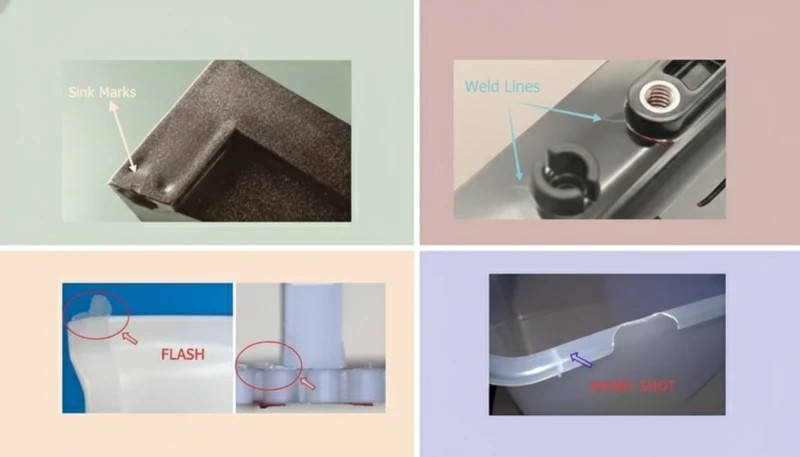
The gas pressure holding phase eliminates common surface defects such as sink marks, weld lines, and flow marks that frequently occur in thick-walled conventional molded parts. Gas pressure acts as an internal packing mechanism, ensuring uniform surface finish across complex geometries. This improvement often eliminates secondary finishing operations, reducing overall production time and costs.
Enhanced Structural Performance
Hollow sections created through GAIM often exhibit superior strength-to-weight ratios compared to solid equivalents. The hollow core design increases the part’s section modulus while reducing weight, resulting in improved bending strength and reduced material stress. This advantage is particularly valuable in automotive and aerospace applications where weight reduction is critical.
Reduced Warpage and Dimensional Stability
Gas pressure helps maintain uniform cooling rates throughout the part cross-section, significantly reducing warpage and improving dimensional stability. Internal stress distribution is more uniform in GAIM parts, leading to better long-term dimensional retention under varying environmental conditions.
| Performance Metric | Conventional Injection Molding | Gas-Assisted Injection Molding | Improvement |
|---|---|---|---|
| Material Usage | 100% baseline | 60-80% of baseline | 20-40% reduction |
| Cycle Time | 100% baseline | 75-90% of baseline | 10-25% reduction |
| Surface Quality Rating | Good (sink marks common) | Excellent (minimal defects) | Significantly improved |
| Tooling Cost | 100% baseline | 110-130% of baseline | 10-30% increase |
| Part Weight | 100% baseline | 60-80% of baseline | 20-40% reduction |
What Are the Common Applications of Gas-Assisted Injection Molding?
The common applications of gas-assisted injection molding are the main categories or options explained in this section. Gas-assisted injection molding finds extensive application across industries where part complexity, weight reduction, and material efficiency3 are critical design requirements. Understanding these applications helps engineers identify opportunities where GAIM provides optimal solutions.
Automotive Industry Applications
The automotive sector represents the largest market for GAIM technology, utilizing the process for both structural and aesthetic components. Common applications include door handles, instrument panel components, bumper supports, and interior trim pieces. Automotive manufacturers particularly value GAIM’s ability to create complex hollow geometries that reduce vehicle weight while maintaining crash safety requirements.
Door handles manufactured using GAIM typically feature internal hollow channels that house mechanical linkages while providing ergonomic exterior surfaces. This design approach eliminates the need for multi-piece assemblies, reducing both manufacturing complexity and potential failure points. Weight reductions of 25-35% are commonly achieved compared to solid molded alternatives.
Consumer Electronics and Appliances
Electronics manufacturers utilize GAIM for housing components, structural frames, and heat dissipation elements. The process enables creation of thin-walled sections with integrated strengthening ribs, essential for portable device housings that must withstand impact while minimizing weight.
Television bezels and monitor frames represent prime GAIM applications, where the hollow internal structure provides cable management channels while maintaining sleek external aesthetics. The improved surface quality eliminates secondary painting operations in many cases, reducing production time and environmental impact.
Furniture and Construction Components
Furniture manufacturers employ GAIM for chair backs, table supports, and modular construction elements. The process enables creation of complex ergonomic surfaces with integrated structural reinforcement, eliminating traditional assembly methods that require multiple components and fasteners.
Construction applications include structural panels, decorative elements, and functional components such as handrails and safety barriers. GAIM’s ability to create hollow sections with precise wall thickness control makes it ideal for applications requiring specific strength-to-weight ratios while meeting building code requirements.
Medical Device Components
Medical device applications utilize GAIM for equipment housings, ergonomic handles, and structural components where weight reduction and surface quality are critical. The process enables creation of complex internal geometries for cable management and component integration while maintaining smooth, cleanable external surfaces required in healthcare environments.
What Are the Different Types of Gas-Assisted Injection Molding?
The different types of gas-assisted injection molding are the main categories or options explained in this section. Gas-assisted injection molding encompasses several distinct process variations, each optimized for specific part geometries and manufacturing requirements. Understanding these variations enables engineers to select the most appropriate method for their specific applications.
Internal Gas Injection (IGI)
Internal Gas Injection represents the most common GAIM variant, where gas is introduced directly into the molten plastic through injection pins positioned within the mold cavity. Gas injection points are typically located at the end of flow paths in thick-walled sections, allowing gas to penetrate and create hollow channels along the plastic flow direction.
IGI systems typically operate at gas pressures ranging from 50-150 bar, with injection timing controlled to within ±0.1 seconds for optimal results. The gas follows thick-walled sections and ribs, creating hollow channels that maintain part strength while reducing material usage. This method is particularly effective for parts with long, thick sections such as automotive handles, structural ribs, and tubular components.
Process control parameters for IGI include gas injection delay time (typically 0.5-2.0 seconds after plastic injection), peak gas pressure, holding pressure profile, and evacuation timing. Precise control of these parameters is essential for achieving consistent hollow channel formation and preventing gas breakthrough at thin-walled sections.
External Gas Injection (EGI)
External Gas Injection introduces pressurized gas at the injection molding machine nozzle, creating a gas-plastic mixture before entering the mold cavity. This method is particularly suitable for parts with multiple thick sections where gas needs to reach various areas of the component.
EGI systems require specialized injection units capable of controlling gas-plastic mixing ratios and maintaining consistent pressure throughout the injection cycle. Gas concentrations typically range from 0.1-0.5% by volume, with nitrogen being the preferred gas due to its inert properties and consistent behavior under pressure.
The primary advantage of EGI lies in its ability to create multiple hollow sections simultaneously without requiring multiple gas injection points in the mold. This reduces mold complexity and manufacturing costs while enabling more uniform gas distribution throughout complex part geometries.
Spill/Short Shot Method
The Spill or Short Shot method involves deliberately underfilling the mold cavity during plastic injection, then using gas pressure to drive additional material into unfilled areas while creating hollow sections in thick-walled regions. This approach provides excellent control over material distribution and hollow channel formation.
Spill systems typically use overflow areas or dedicated spill cavities to accommodate excess material displaced by gas injection. The overflow material can often be recycled directly back into the process, minimizing material waste. Gas pressures for spill applications range from 30-100 bar, generally lower than IGI systems due to the reduced resistance from partially filled cavities.
This method excels in applications requiring precise wall thickness control and complex internal geometries. Automotive structural components and large appliance housings frequently utilize spill GAIM to achieve optimal material distribution while maintaining dimensional accuracy.
“Nitrogen is the standard gas choice for most gas-assisted injection molding production programs.”True
True. Nitrogen is widely used because it is inert, stable, and predictable across many molding resins. Alternative gases require material-specific validation and are not the default choice for production GAIM.
“Wall thickness ratios in GAIM should always exceed 5:1 between thick and thin sections for optimal gas penetration.”False
False. Optimal wall thickness ratios for GAIM typically range from 2:1 to 4:1. Ratios above 5:1 can cause uncontrolled gas breakthrough, surface quality loss, and local weakness. The right ratio depends on resin viscosity, gas-channel length, and the structural role of the hollow rib.
How Does Gas-Assisted Injection Molding Compare to Conventional Injection Molding?
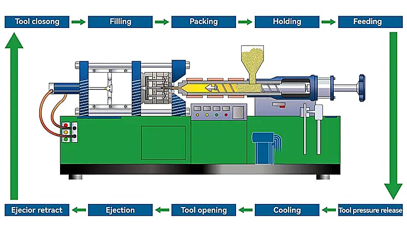
Gas-assisted injection molding is more competitive than conventional injection molding when the cost, lead time, and quality tradeoffs below match your program needs. Gas-assisted injection molding differs from conventional injection molding by adding a controlled nitrogen pressure stage after plastic fill, so the process can core thick sections, reduce sink marks, and lower part weight when geometry supports it. The conventional sequence described in the steps of injection molding still applies, but GAIM adds gas timing, pressure holding, evacuation, and stricter validation. Engineers should compare tooling cost, process complexity, part strength, surface quality, and annual volume before selecting GAIM.
Process Complexity and Equipment Requirements
Conventional injection molding utilizes relatively straightforward equipment consisting of an injection unit, clamping system, and basic mold. GAIM systems require additional gas injection equipment, pressure control systems, and specialized mold components including gas injection pins and evacuation systems. This increased complexity translates to higher initial equipment investment but enables capabilities impossible with conventional methods.
Setup and optimization time for GAIM typically requires 2-3 times longer than conventional molding due to the need to optimize gas injection timing, pressure profiles, and evacuation sequences. However, once optimized, GAIM processes often demonstrate superior consistency and reduced variation compared to conventional thick-wall molding.
Design Flexibility and Part Complexity
GAIM enables creation of complex internal geometries, hollow sections, and integrated features that would require multiple components in conventional molding. This capability often eliminates assembly operations and reduces overall part count in complex products. Conventional molding excels in high-volume production of simple geometries where tooling costs and cycle time optimization are primary concerns.
Wall thickness requirements differ significantly between the methods. Conventional molding performs optimally with uniform wall thickness (typically 1-4mm), while GAIM can accommodate varying wall thickness and creates hollow sections in areas exceeding 6mm thickness. This flexibility enables designers to optimize material placement for structural requirements rather than molding limitations.
Quality and Performance Characteristics
Surface quality advantages of GAIM become particularly pronounced in thick-walled applications where conventional molding typically produces sink marks, weld lines, and internal stress concentrations. GAIM’s gas pressure holding phase acts as an internal packing mechanism, ensuring uniform surface finish and dimensional stability.
Mechanical properties of GAIM parts often exceed those of equivalent solid molded parts due to optimized stress distribution and reduced internal tensions. The hollow core structure increases section modulus while reducing weight, resulting in improved strength-to-weight ratios critical for structural applications.
Economic Considerations
Material cost savings in GAIM typically offset higher processing costs for parts exceeding certain size and complexity thresholds. The break-even point generally occurs at part weights above 50-100 grams, depending on material costs and production volumes. High-volume production (>100,000 parts annually) usually favors GAIM due to cumulative material savings and reduced secondary operations.
Tooling costs for GAIM typically exceed conventional molding by 15-30% due to gas injection system integration and specialized components. However, elimination of secondary assembly operations and improved first-pass quality often provide overall cost advantages for complex parts.

What Design Guidelines Should Engineers Follow for GAIM?
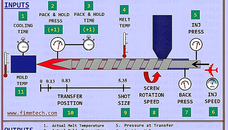
Engineers should design GAIM parts around predictable gas flow: controlled thick-to-thin transitions, planned gas channels, smooth radii, stable venting, and resin flow behavior must be reviewed before mold steel is cut. The molding machine setup also matters, so the DFM review should consider the screw injection molding machine, material MFI, wall thickness ratio, gas pin location, and target cycle time together.
Wall Thickness Considerations and Ratios
Optimal wall thickness ratios represent the most critical design parameter in GAIM applications. The thick-to-thin wall ratio should typically range from 2:1 to 4:1 to ensure proper gas penetration while preventing breakthrough at thin sections. Areas intended for gas penetration should maintain minimum thickness of 4-6mm, while adjacent thin walls should not exceed 2-3mm thickness.
Gradual thickness transitions prevent gas from taking unintended paths and ensure predictable hollow channel formation. Transition zones should extend over distances of at least 3-5 times the thickness difference, with maximum thickness change rates not exceeding 25% per unit length. Sharp thickness changes can cause gas breakthrough or incomplete penetration, compromising both part quality and structural integrity.
Material selection significantly influences optimal thickness ratios. Semi-crystalline materials like polyamides and polyoxymethylene typically require thicker gas penetration sections (6-8mm) compared to amorphous materials like ABS or polycarbonate (4-6mm) due to their different flow and cooling characteristics.
Gas Channel Design and Flow Path Optimization
Gas injection point placement requires careful analysis of part geometry and anticipated flow patterns. Injection points should be positioned at flow path extremities in the thickest part sections, typically at distances of 50-150mm from thin-walled areas depending on material viscosity and part complexity.
Multiple injection points may be necessary for large or complex parts, but should be positioned to prevent gas flow interference. Minimum spacing between injection points should exceed 100mm, with flow paths designed to prevent gas streams from converging in thin-walled sections. Flow analysis software specifically developed for GAIM applications can optimize injection point placement and predict gas penetration patterns.
Gas evacuation considerations are equally important, requiring either return flow through injection points or dedicated evacuation channels. Evacuation path design must ensure complete gas removal while preventing plastic material from entering gas supply systems. Check valve systems and purge sequences help maintain system cleanliness and prevent contamination.
Rib Design and Structural Optimization
Ribs intended for gas penetration should maintain consistent thickness along their length and connect smoothly to surrounding part geometry. Rib thickness should generally range from 80-120% of adjacent wall thickness to ensure adequate gas penetration without compromising structural performance. Rib height-to-thickness ratios should not exceed 3:1 to prevent buckling or distortion during cooling.
Integration of ribs with gas channels requires careful attention to intersection geometry and flow transitions. Smooth radius transitions (minimum 0.5mm) at rib intersections prevent gas flow disruption and reduce stress concentration points. Multiple ribs should be spaced to allow independent gas penetration without interference between adjacent channels.
Draft angles for GAIM ribs typically range from 0.5-1.5 degrees, similar to conventional molding requirements. However, hollow ribs may require slightly increased draft angles (1.0-2.0 degrees) to accommodate potential dimensional variations from gas pressure effects during cooling.
Material Selection Criteria
Material selection for GAIM applications must consider gas solubility, melt flow characteristics, and cooling behavior in addition to standard mechanical property requirements. Materials with low gas solubility, such as polyolefins and styrenics, generally provide better gas channel definition and easier gas evacuation compared to materials with higher gas solubility like polyamides.
Melt flow index (MFI) requirements for GAIM typically favor materials with moderate to high flow rates (MFI 10-50 g/10min for most applications) to ensure adequate mold filling before gas injection while maintaining sufficient viscosity for proper gas channel formation. Extremely high flow materials may allow premature gas breakthrough, while low flow materials may not achieve complete mold filling.
Crystallization behavior affects gas penetration patterns and final part properties. Semi-crystalline materials require careful temperature control to manage crystallization rates and prevent premature solidification that could block gas channels. Amorphous materials generally provide more predictable gas penetration but may require higher gas pressures due to their higher melt viscosity at processing temperatures.
How Can ZetarMold Support Your Gas-Assisted Injection Molding Project?
ZetarMold supports gas-assisted injection molding projects by turning early part drawings into a practical DFM, mold-trial, and production validation plan. In our Shanghai factory, our engineers review wall thickness, gas-channel layout, resin behavior, machine tonnage, and injection molding production time before recommending whether GAIM is truly justified for cost, quality, and delivery.
Advanced Manufacturing Capabilities
Factory Insight: For gas-assisted injection molding feasibility reviews, ZetarMold combines 20+ years of molding and tooling experience with 47 injection molding machines from 90T to 1850T, 8 senior engineers, and experience across 400+ plastic materials. That matters because gas-channel design, nitrogen timing, sink-mark prevention, and mold trial validation must be checked together before a project is released to production under ISO-managed quality systems.
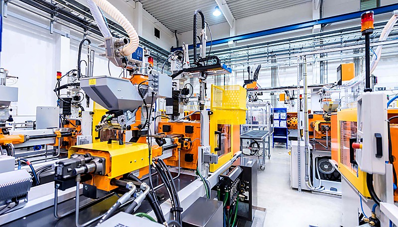
Our Shanghai facility operates 45+ injection molding machines ranging from 90T to 1850T clamping force, providing the flexibility to handle GAIM projects across a wide size spectrum. Each machine is equipped with precision gas injection systems capable of maintaining pressure control within ±2 bar accuracy and timing precision of ±0.1 seconds, essential for consistent GAIM results.
ZetarMold’s material capabilities encompass 400+ engineering plastics and commodity resins, including specialized GAIM-optimized grades from leading suppliers. Our material selection expertise helps identify optimal polymer choices based on gas solubility characteristics, processing requirements, and end-use performance specifications. We maintain comprehensive material property databases specific to GAIM applications, enabling accurate process parameter prediction and optimization.
Our quality management system operates under ISO 9001:2015 certification with specialized procedures for GAIM process validation and control. Statistical process control systems monitor critical parameters including gas pressure profiles, injection timing sequences, and dimensional accuracy across production runs. This systematic approach ensures consistent part quality and enables rapid identification of process variations.
Engineering Excellence and Technical Support
ZetarMold’s team of 8 senior engineers possesses extensive GAIM experience across automotive, electronics, and industrial applications. Our engineering services include comprehensive design for manufacturability (DFM) analysis, mold flow simulation using specialized GAIM software, and process optimization support throughout project development.
Design consultation services help optimize part geometry for GAIM processing, including wall thickness analysis, gas injection point placement, and structural optimization recommendations. Our engineers utilize advanced simulation tools to predict gas penetration patterns, identify potential processing challenges, and optimize tooling design before manufacturing begins.
Prototype development capabilities enable rapid validation of GAIM designs using production-representative processes and materials. Our prototyping approach includes iterative optimization of gas injection parameters, material selection validation, and mechanical property testing to ensure design requirements are met before committing to production tooling.
Global Communication and Project Management
With 30+ fluent English speakers on staff, ZetarMold ensures clear communication throughout project development and production phases. Our project management approach includes regular progress updates, technical documentation in English, and direct engineer-to-engineer communication to resolve technical challenges efficiently.
Quality documentation packages include comprehensive inspection reports, material certifications, and process parameter records formatted to meet international standards. Our traceability systems maintain complete production history for each part batch, supporting quality investigations and continuous improvement initiatives.
Supply chain management capabilities include global shipping coordination, customs documentation, and quality assurance protocols designed for international manufacturing partnerships. We work closely with sourcing teams to establish optimal logistics solutions and maintain consistent delivery schedules.
Partnership and Long-Term Support
ZetarMold’s approach to client partnerships extends beyond initial project delivery to include ongoing technical support, process optimization, and capacity scaling as production requirements evolve. Our experienced team understands the unique challenges of GAIM manufacturing and provides proactive support to maintain consistent quality and efficiency.
Continuous improvement programs help optimize GAIM processes over time, identifying opportunities for cycle time reduction, material savings, and quality enhancement. Regular process reviews and capability assessments ensure production methods remain aligned with evolving technical requirements and industry best practices.
For companies seeking reliable injection molding supplier sourcing for gas-assisted injection molding, ZetarMold can review the part geometry, recommend whether GAIM is technically justified, and prepare a DFM path that covers gas-channel layout, material choice, tooling risk, trial validation, and production quality control.
Frequently Asked Questions
What parts are best suited for gas-assisted injection molding?
Gas-assisted injection molding is strongest for thick-wall plastic parts, long handles, structural ribs, large housings, chair components, appliance frames, and parts where weight reduction or sink-mark control is important. The process works best when the design has a planned gas channel and enough plastic volume for nitrogen to core out the interior. It is less useful for very thin, simple, low-volume parts where conventional injection molding already produces stable quality without visible sink marks or excessive resin use. This makes geometry screening the first decision point.
Does gas-assisted injection molding always reduce cost?
No. Gas-assisted injection molding can reduce resin usage, improve surface quality, and lower part weight, but it also adds tooling complexity, gas pins or nozzles, gas-control equipment, process development time, and more validation work. The cost benefit should be calculated from part geometry, annual volume, resin price, tooling cost, expected scrap reduction, cycle time, and the value of eliminating secondary assembly. A DFM review and trial-shot plan are needed before treating GAIM as a guaranteed cost-saving method. Buyers should request a written cost model.
What is the main quality risk in gas-assisted injection molding?
The main quality risk is uncontrolled gas penetration. If the gas path is poorly designed or the pressure timing is wrong, nitrogen can blow through the melt front, create weak sections, leave inconsistent hollow channels, or produce cosmetic defects on the visible surface. Wall thickness transitions, gas-channel radius, resin viscosity, venting, injection speed, and holding pressure all influence the result. This is why GAIM projects should include DFM, flow simulation when needed, mold trial validation, and documented process windows. Those records reduce repeat-production risk.
Which gas is normally used in GAIM production?
Nitrogen is normally used in production gas-assisted injection molding because it is inert, stable, widely available, and predictable with many common thermoplastics. Its behavior during gas penetration and pressure holding is well understood by molders, which makes process setup more repeatable. Other gases should only be considered after material-specific testing because they may affect foaming behavior, surface finish, gas solubility, or process stability. For most export manufacturing projects, nitrogen remains the practical default. It also simplifies supplier qualification and production documentation for repeat orders.
How should buyers evaluate a GAIM supplier?
Buyers should evaluate a GAIM supplier by asking for DFM support, previous thick-wall molding experience, machine tonnage range, gas-assist tooling knowledge, resin recommendations, trial-shot validation, and quality documentation. The supplier should explain where gas will enter, how the hollow channel will form, and how sink marks or blow-through will be controlled. For overseas projects, buyers should also check English communication, project management discipline, mold-maintenance capability, and whether the supplier can provide inspection reports and process records. These checks prevent sourcing mistakes.
-
Gas-Assisted Injection Molding: Injection Molding Handbook refers to rosato and Rosato provide baseline engineering references for gas-assisted injection molding process fundamentals, pressure control, and tooling considerations. ↩
-
ISO 20421-1:2019: ISO 20421 search refers to iSO 20421-1:2019 is used as the standards reference point for gas-assisted injection molding terminology and general process principles. ↩
-
material efficiency: PlasticsEurope facts refers to plasticsEurope market data gives context for material efficiency, waste reduction, and plastics manufacturing trends discussed in this article. ↩


