 Skip to content
Moulage par injection de l'UHMWPE
Découvrez le moulage par injection de l'UHMWPE, ses avantages, ses applications et son processus de fabrication de composants en polyéthylène ultra-durables et résistants à l'usure.
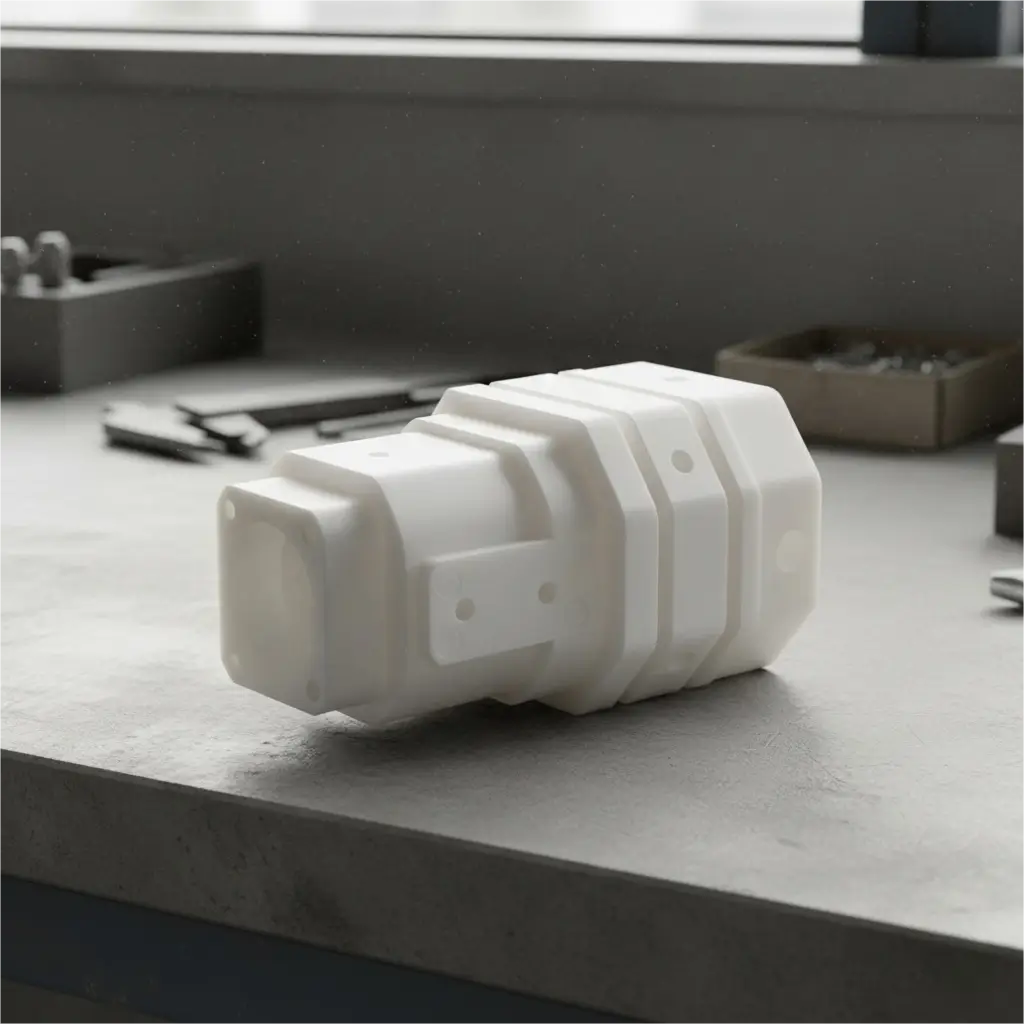
Avancé UHMWPE Moulage par injection
ZetarMold est l'un des rares fabricants à pouvoir mouler par injection l'UHMWPE. Grâce à nos installations de pointe, à notre expertise approfondie des matières plastiques et à notre processus de moulage exclusif, nous proposons des solutions à la fois efficaces et rentables.
Pourquoi l'usiner quand on peut le mouler ? De plus en plus d'industries découvrent les avantages de l'UHMWPE pour les équipements critiques.
UHMWPE
Moulage spécialisé
"De plus en plus d'industries découvrent les avantages de l'UHMW-PE pour les équipements critiques. Chez ZetarMold, notre équipe d'ingénieurs collabore étroitement avec le service commercial pour vous aider à développer la structure UHMW qui répondra aux exigences uniques de votre application spécifique. Nous sommes spécialisés dans le moulage par injection d'UHMW sur mesure - explorez les industries que nous servons et voyez comment nous pouvons contribuer à votre succès."
Ressources pour Le guide complet du moulage par injection de l'UHMWPE
Qu'est-ce que le polyéthylène à très haut poids moléculaire (UHMWPE) ?
Le polyéthylène à ultra-haut poids moléculaire, communément abrégé en UHMWPE ou UHMW, est un sous-ensemble spécialisé de la famille des polyéthylènes thermoplastiques. Comme son nom l'indique, le polyéthylène UHMW est caractérisé par des chaînes de polymères extrêmement longues, ce qui lui confère un poids moléculaire très élevé.
Pour mettre les choses en perspective :
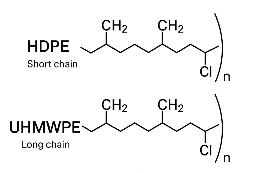
- Polyéthylène haute densité (PEHD)un plastique couramment utilisé pour les bouteilles et les récipients, a généralement un poids moléculaire compris entre 100 000 et 500 000 g/mol.
- Polyéthylène à très haut poids moléculaire (UHMWPE) a un poids moléculaire qui varie généralement de 3,1 millions à plus de 7 millions g/molparfois jusqu'à 10 millions de g/mol.
Ces chaînes moléculaires exceptionnellement longues et enchevêtrées sont à l'origine des propriétés légendaires de l'UHMWPE. Imaginez un bol de spaghettis cuits par rapport à un bol de pâtes courtes. Il est beaucoup plus difficile de séparer les longs spaghettis que les morceaux plus courts. De même, les longues chaînes de polymères de l'UHMWPE sont incroyablement efficaces pour transférer et dissiper la charge et l'énergie. Cette structure moléculaire confère au matériau une immense ténacité, une résistance supérieure à l'usure et une grande résistance aux chocs.
Contrairement à la plupart des thermoplastiques, l'UHMWPE ne fond pas vraiment en un liquide fluide lorsqu'il est chauffé au-dessus de son point de fusion (environ 135°C / 275°F). Au lieu de cela, il se ramollit en un état amorphe semblable à un gel. Sa viscosité reste extrêmement élevée, se comportant davantage comme une pâte dense que comme un liquide. Ce comportement rhéologique unique est la principale raison pour laquelle l'UHMW est traditionnellement traité par moulage par compression ou par extrusion à bélier, où le matériau est forcé à prendre une forme sous une pression immense. Le moulage par injection de l'UHMWPE est donc une variante hautement spécialisée et difficile d'un processus standard.
Quels sont les types de matériaux UHMWPE ?
L'UHMWPE standard (vierge) est un matériau remarquable en soi, mais il peut être amélioré et modifié pour répondre aux exigences d'applications spécifiques. Ces différents grades et formulations augmentent sa polyvalence dans de nombreuses industries.
1. Qualité vierge (non remplie) :
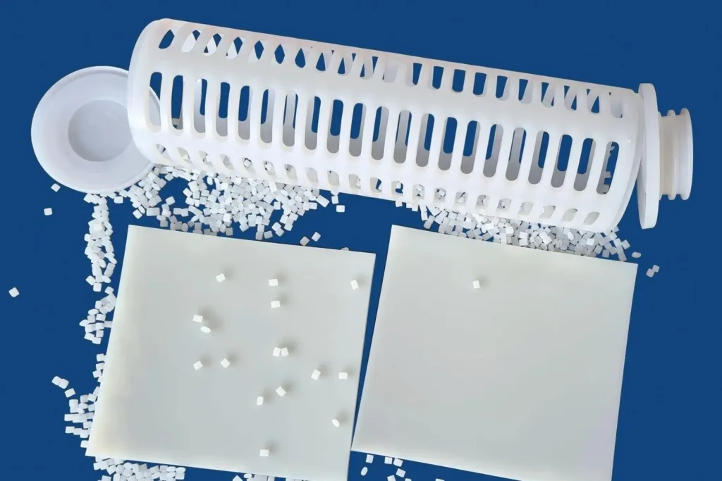
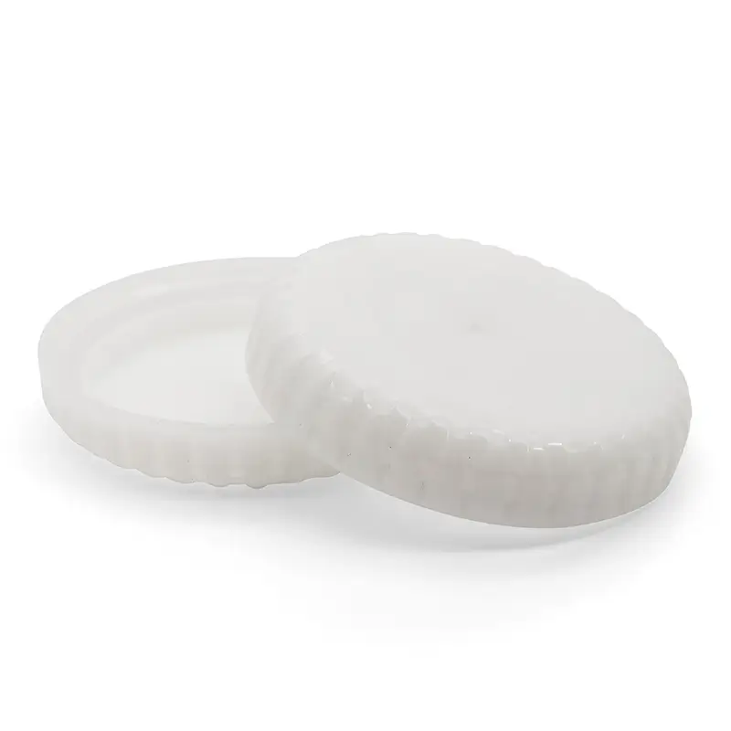
Il s'agit de la forme pure et non altérée de l'UHMWPE. Il est connu pour ses excellentes propriétés générales, notamment sa grande résistance aux chocs, sa faible friction et sa grande résistance aux produits chimiques. De nombreux grades vierges sont conformes aux réglementations de la FDA et de l'USDA, ce qui les rend adaptés aux applications de traitement et de manipulation des aliments. Ils sont généralement de couleur blanche ou naturelle.
2. Grades améliorés et remplis :
Des additifs sont mélangés à la résine UHMWPE de base pour améliorer les propriétés spécifiques.
- UHMWPE rempli d'huile : Dans ce grade, une huile, une cire ou un autre lubrifiant de qualité alimentaire est mélangé à la matrice polymère au cours de la fabrication. On obtient ainsi un matériau "à lubrification interne", ce qui se traduit par un coefficient de frottement encore plus faible (jusqu'à 20% de moins que le grade vierge) et une meilleure résistance à l'usure, en particulier dans les applications à fonctionnement à sec. Il est idéal pour les roulements, les bagues et les guides de chaîne où la lubrification externe n'est pas possible.
- UHMWPE chargé de verre : L'ajout de billes ou de fibres de verre microscopiques augmente la rigidité (module de flexion), la résistance à la compression et la stabilité dimensionnelle du matériau. Bien qu'elle réduise légèrement la résistance aux chocs, elle offre de meilleures performances sous des charges statiques élevées et à des températures élevées.
- UHMWPE chargé de carbone : De la poudre ou des fibres de carbone sont ajoutées pour rendre le matériau statiquement dissipatif ou conducteur. Cette caractéristique est cruciale pour les applications dans des environnements explosifs ou lorsque des composants électroniques sensibles doivent être protégés contre les décharges électrostatiques (ESD). Les charges de carbone améliorent également la rigidité et la conductivité thermique.
- UHMWPE chargé de céramique : L'inclusion de particules de céramique (comme l'alumine ou le carbure de silicium) augmente considérablement la résistance à l'abrasion. Ces qualités sont conçues pour les applications d'usure les plus exigeantes, telles que la manipulation de boues abrasives dans l'exploitation minière, l'agriculture ou la manutention de matériaux en vrac.
3. UHMWPE réticulé (XLPE) :
Dans cette variante de qualité médicale, les pièces en UHMWPE sont soumises à un processus de post-moulage, généralement une irradiation par rayons gamma ou par faisceaux d'électrons. Ce rayonnement à haute énergie permet aux différentes chaînes de polymères de former des liaisons chimiques (réticulations) les unes avec les autres. Ce réseau tridimensionnel améliore considérablement la résistance à l'usure et réduit le fluage (déformation sous une charge constante). L'UHMWPE réticulé est le matériau de référence pour les implants orthopédiques, tels que les prothèses de la hanche et du genou, où la minimisation des débris d'usure est essentielle pour la longévité de l'implant.
4. Grades antimicrobiens :
Pour les applications dans les industries alimentaires et médicales, des agents antimicrobiens peuvent être incorporés dans la résine UHMWPE. Ces agents inhibent la croissance des bactéries, des moisissures et des champignons à la surface de la pièce finie, améliorant ainsi l'hygiène et la sécurité.
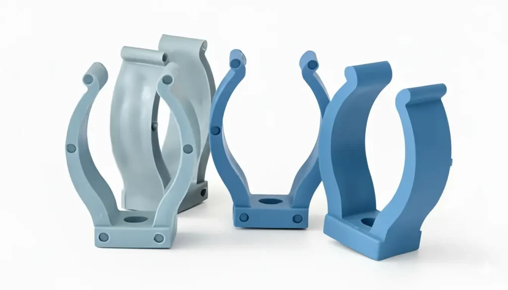
5. Code couleur pour les grades :
Alors que l'UHMWPE vierge est naturellement blanc, des pigments peuvent être ajoutés pour créer des pièces de différentes couleurs. Ce procédé est souvent utilisé à des fins d'organisation, comme le codage par couleur de différents types de planches à découper, de pièces de machines pour des lignes de production spécifiques ou de composants critiques pour la sécurité.
Quelle est la différence entre le PE, le PEHD, le PEBD, le PEBDL et l'UHMWPE ?
Avant de plonger dans le moulage par injection de l'UHMWPE, il est essentiel de comprendre sa place au sein de la vaste famille des polyéthylènes (PE). Bien qu'ils partagent tous le nom de "polyéthylène", des différences subtiles dans leur structure moléculaire entraînent un monde de différences dans leurs performances, allant des sacs en plastique flexibles que nous utilisons quotidiennement aux composants de qualité industrielle qui peuvent résister à une abrasion extrême.
Imaginez les molécules de polymères comme de longues chaînes. Les longueur de ces chaînes, leur forme (qu'ils soient linéaires ou ramifiés), et comment les ils peuvent se serrer les uns contre les autres déterminent collectivement les propriétés macroscopiques du matériau final.
1. Polyéthylène basse densité (PEBD) :
Le PEBD a été l'un des premiers grades de polyéthylène à être produit, et sa structure moléculaire est la clé de ses propriétés.
① Structure moléculaire : Les chaînes moléculaires du PEBD sont très ramifiées, avec des chaînes latérales longues et courtes, ressemblant à un arbre désorganisé. Ces ramifications empêchent les chaînes de s'agglutiner de manière ordonnée, ce qui se traduit par de faibles forces intermoléculaires et une faible cristallinité.
② Caractéristiques principales :
- Souplesse et flexibilité : En raison de l'agencement lâche de ses molécules, le PEBD est très souple, flexible et présente une excellente ductilité.
- Grande clarté : Sa faible cristallinité lui confère une bonne transparence.
- Faible densité : La densité est généralement comprise entre 0,910 et 0,925 g/cm³.
- Faibles résistance et dureté : Il ne peut pas supporter des charges ou des pressions élevées.
- Faible résistance à la chaleur : Il a un point de fusion bas et ne convient pas aux applications à haute température.
③ Applications courantes :
- Films d'emballage alimentaire, film étirable.
- Sacs en plastique, sacs d'épicerie.
- Tubes flexibles, flacons à presser (par exemple, pour les condiments ou la lotion).
- Films agricoles.
En bref : Le PEBD est le membre "souple et flexible" de la famille des PE, idéal pour les applications d'emballage et de film où une grande résistance n'est pas nécessaire.

2. Polyéthylène linéaire de faible densité (LLDPE) :
Le PEBDL peut être considéré comme une version améliorée du PEBD, offrant une résistance accrue tout en conservant une grande partie de sa flexibilité.
① Structure moléculaire : Le PEBDL a une chaîne principale linéaire mais comporte de nombreuses branches courtes et uniformes. Contrairement aux branches longues et désordonnées du PEBD, cette structure plus régulière permet au polymère de conserver sa cohésion lorsqu'il est soumis à des contraintes.
② Caractéristiques principales :
- Résistance supérieure à la déchirure et à la perforation : C'est l'avantage le plus important du PEBDL par rapport au PEBD. La structure moléculaire répartit mieux les contraintes.
- Résistance à la traction et ténacité élevées : Il se comporte beaucoup mieux sous tension et a moins tendance à se rompre.
- Flexibilité conservée : Bien qu'il soit légèrement plus rigide que le PEBD, il est toujours considéré comme un matériau souple.
③ Applications courantes :
- Film étirable industriel pour la palettisation des marchandises.
- Sacs poubelles robustes et doublures industrielles.
- Géomembranes, tuyaux d'irrigation agricole.
- Jouets durables.
En bref : Le PEBDL est une version "plus dure" du PEBD, conçue pour les films et les applications flexibles qui exigent une plus grande résistance à la déchirure et à la perforation.
3. Polyéthylène haute densité (PEHD) :
Le PEHD est le cheval de bataille "solide et rigide" de la famille des polyéthylènes et l'un des plastiques durs les plus courants dans notre vie quotidienne.
① Structure moléculaire : Le PEHD se caractérise par des chaînes moléculaires très linéaires et très peu ramifiées. Cette structure ordonnée permet aux chaînes de se regrouper très étroitement et de former des régions hautement cristallines, ce qui se traduit par de fortes forces intermoléculaires.
② Caractéristiques principales :
- Densité et dureté élevées : Avec une densité généralement comprise entre 0,941 et 0,965 g/cm³, il est dur, rigide.
- Haute résistance à la traction : Il peut résister à une force nettement supérieure à celle du LDPE et du LLDPE.
- Excellente résistance chimique : Il est très résistant à de nombreux acides, bases et solvants.
- Opaque : Sa haute cristallinité le rend naturellement blanc laiteux ou opaque.
- Bonne résistance à l'usure : Pour un plastique de base, sa résistance à l'abrasion est respectable (mais loin de celle de l'UHMWPE).
③ Applications courantes :
- Pots de lait, bouteilles de jus de fruit, bouteilles de shampoing et autres récipients rigides.
- Conduites de gaz, d'eau et d'évacuation.
- Planches à découper en plastique, bacs de rangement.
- Jouets pour enfants, mobilier d'extérieur.
En bref : le PEHD est le plastique "rigide et durable" de choix pour la fabrication d'une grande variété de conteneurs rigides, de tuyaux et de produits durables.
4. Polyéthylène à très haut poids moléculaire (UHMWPE) :
Le polyéthylène UHMWPE représente le summum des performances du polyéthylène. Il pousse la structure linéaire du PEHD à l'extrême, ce qui lui confère des propriétés exceptionnelles qu'aucun autre PE ne peut égaler.
① Structure moléculaire : Les chaînes moléculaires de l'UHMWPE sont également linéaires, mais leur longueur est stupéfiante - 10 à 20 fois plus longue que celle du PEHD, voire plus. Son poids moléculaire est généralement compris entre 3,1 et plus de 7 millions de g/mol, alors que celui du PEHD n'est généralement que de 100 000 à 500 000 g/mol. Ces chaînes extrêmement longues sont fortement enchevêtrées les unes dans les autres, comme un bol de spaghettis trop cuits.
② Caractéristiques principales :
- Résistance à l'abrasion inégalée : C'est la caractéristique principale de l'UHMWPE. Dans les scénarios de glissement et d'usure abrasive, il surpasse presque tous les autres thermoplastiques et de nombreux métaux, y compris l'acier au carbone. Les longues chaînes sont incroyablement difficiles à arracher de la surface.
- Résistance extrême aux chocs : Il possède la plus grande résistance aux chocs de tous les thermoplastiques, ce qui lui vaut le surnom de "pratiquement incassable". Il conserve cette résistance même à des températures cryogéniques (-200°C).
- Coefficient de frottement extrêmement faible : La surface est exceptionnellement lisse et possède des propriétés autolubrifiantes remarquables, comparables à celles du PTFE (Téflon).
- Résistance chimique supérieure : Il hérite de l'inertie chimique de la famille PE et l'améliore.
- Absorption d'eau nulle : Il n'absorbe pratiquement pas d'humidité, ce qui lui confère une excellente stabilité dimensionnelle.
③ Difficulté de traitement : En raison de l'extrême longueur de sa chaîne, sa viscosité à l'état fondu est astronomique. Au-dessus de son point de fusion, il ne s'écoule pas comme un véritable liquide, mais se ramollit en un état caoutchouteux, semblable à un gel. Il est donc impossible de le transformer à l'aide des techniques conventionnelles de moulage par injection ou d'extrusion. Il nécessite des méthodes hautement spécialisées, telles que le moulage par injection spécialisé dont il est question dans ce guide, le moulage par compression ou l'extrusion par bélier.
④ Applications courantes :
- Implants orthopédiques (revêtements résistants à l'usure pour les hanches et les genoux artificiels).
- Plaques balistiques pour les gilets pare-balles, gants anti-coupures.
- Bandes d'usure industrielles, guides de chaîne, engrenages et roulements.
- Défenses de quai pour les ports, revêtements pour les trémies de minéraux et de céréales.
En bref : L'UHMWPE est le "guerrier ultime" de la famille des polyéthylènes. Il tire parti de ses chaînes moléculaires extrêmement longues pour offrir une résistance à l'usure, une résistance aux chocs et une autolubrification inégalées pour les défis d'ingénierie les plus exigeants.
5. Tableau de comparaison rapide :
| Propriété | LDPE | LLDPE | PEHD | UHMWPE |
|---|---|---|---|---|
| Structure moléculaire | Hautement ramifié | Linéaire à branches courtes | Très linéaire | Chaînes linéaires extrêmement longues |
| Poids moléculaire (g/mol) | Faible (~50 000) | Faible (~100 000) | Moyen (100k - 500k) | Extrêmement élevé (>3 100 000) |
| Densité | Faible | Faible | Haut | Faible (mais bien tassé) |
| Dureté / Rigidité | Très souple, flexible | Souple, flexible | Dur, rigide | Dureté moyenne, extrêmement résistante |
| Résistance à la traction | Faible | Moyen | Haut | Très élevé |
| Résistance aux chocs | Bon | Excellent | Bon | Remarquable (le plus élevé des thermoplastiques) |
| Résistance à l'abrasion | Pauvre | Juste | Bon | Inégalé (Best of Thermoplastics) |
| Capacité de traitement | Facile | Facile | Facile | Extrêmement difficile |
| Application typique | Sacs, Film | Film étirable, doublures | Bouteilles, tuyaux, bacs | Implants, armures, pièces d'usure |
Quelles sont les caractéristiques de l'UHMWPE ?
Les "caractéristiques" de l'UHMWPE se réfèrent à ses caractéristiques qualitatives et observables qui définissent son comportement et son toucher. Ce sont ces caractéristiques qui le rendent si désirable pour des applications exigeantes.
- Une résistance exceptionnelle : L'UHMWPE est souvent décrit comme "virtuellement incassable". Il peut absorber d'énormes quantités d'énergie d'impact sans se fracturer, se fissurer ou se briser, même à des températures cryogéniques (jusqu'à -200°C).
- Autolubrifiant Nature : Le matériau a un aspect cireux et glissant distinct. Ses molécules ont une très faible affinité avec les autres surfaces, ce qui se traduit par un coefficient de frottement extrêmement faible. Cette propriété "autolubrifiante" signifie qu'il peut fonctionner en contact direct avec d'autres pièces avec une usure minimale et sans avoir besoin de lubrifiants externes.
- Résistance exceptionnelle à l'abrasion : C'est la principale caractéristique de l'UHMWPE. Il surpasse presque tous les autres thermoplastiques et de nombreux métaux, y compris le carbone et l'acier inoxydable, dans les scénarios de glissement et d'abrasion. Les longues chaînes de polymères résistent aux particules abrasives.
- Inertie chimique : En tant que membre de la famille des polyéthylènes, l'UHMWPE est chimiquement très stable. Il est très résistant à une large gamme de produits chimiques corrosifs, y compris la plupart des acides forts, des alcalis, des solvants organiques et des agents de nettoyage. Il n'est attaqué que par les acides fortement oxydants.
- Léger : Avec une densité d'environ 0,93-0,95 g/cm³, l'UHMWPE est plus léger que l'eau, ce qui signifie qu'il flotte. Cette faible densité en fait un excellent choix pour les applications où la réduction du poids est une priorité sans sacrifier la résistance et la durabilité.
- Négligeable Absorption d'humidité : L'UHMWPE n'est pas poreux et n'absorbe pratiquement pas d'eau (<0,01%). Cela signifie que ses dimensions et ses propriétés restent stables même lorsqu'il est entièrement immergé ou utilisé dans des environnements à forte humidité. Il est également résistant aux taches et facile à nettoyer.
- Amortissement supérieur des bruits et des vibrations : La structure moléculaire du matériau est excellente pour absorber l'énergie, ce qui se traduit par un amortissement efficace du bruit et des vibrations. Il est donc idéal pour les engrenages, les rouleaux et les composants des convoyeurs, ce qui permet d'obtenir des machines plus silencieuses.
- Biocompatibilité : L'UHMWPE de qualité médicale n'est pas toxique et ne provoque pas de réaction nocive du corps humain, ce qui en fait un matériau sûr et fiable pour les implants chirurgicaux et les dispositifs médicaux.
Les matériaux UHMWPE peuvent-ils être moulés par injection ?
Oui, mais pas avec un processus standard. C'est le défi central et le concept le plus important à saisir.
Toute tentative de moulage par injection de l'UHMWPE à l'aide de machines et de paramètres conventionnels conçus pour des matériaux tels que le polypropylène ou l'ABS se soldera par un échec. La viscosité à l'état fondu astronomique du matériau l'empêche de s'écouler à travers les portes, les canaux et les cavités de moulage à parois minces standard. Il provoquera probablement un "short shot" (remplissage incomplet) ou endommagera la machine de moulage en raison d'une augmentation excessive de la pression.
1. Le moulage par injection de l'UHMWPE est un processus hautement spécialisé qui nécessite.. :
① Résines spécialement formulées : Les fournisseurs de matériaux ont mis au point des résines UHMWPE exclusives pour le moulage par injection. Celles-ci ont souvent un poids moléculaire légèrement inférieur (tout en restant dans la gamme "ultra-haute") ou contiennent des additifs améliorant l'écoulement qui réduisent la viscosité juste assez pour rendre le traitement possible sans compromettre de manière significative les propriétés finales.
② Machines de moulage par injection modifiées : Les machines doivent être robustes et capables de générer des pressions d'injection extrêmement élevées - souvent supérieures à 30 000 ou 40 000 psi. Elles peuvent être dotées de vis spécialisées (par exemple, de faibles taux de compression), de systèmes hydrauliques améliorés et de cylindres et vis trempés et résistants à l'usure pour faire face à la nature abrasive de certaines qualités de charges.
③ Conception de moules spécialisés : Les moules pour UHMWPE doivent être conçus pour s'adapter à la faible fluidité et au retrait élevé du matériau. Il s'agit notamment d'utiliser des canaux larges et arrondis, des portes larges et directes, une construction robuste pour résister à une pression élevée et un placement stratégique des canaux de refroidissement.
④ Expert Process Control : La fenêtre de traitement pour l'UHMWPE est extrêmement étroite. Elle requiert des techniciens expérimentés qui savent comment équilibrer la température, la pression, la vitesse d'injection et le temps de refroidissement pour obtenir une pièce correctement remplie et entièrement fusionnée.
En résumé, l'UHMWPE peut être moulé par injection, mais il s'agit d'une discipline de niche, de niveau expert, qui comble le fossé entre les techniques traditionnelles de moulage par injection et de moulage par compression.
Par conséquent, le moulage par injection de l'UHMWPE est une technique hautement spécialisée, que l'on peut décrire comme un processus hybride qui se situe quelque part entre le moulage par injection traditionnel et le moulage par compression. Il exige non seulement des qualités de résine spéciales et un équipement modifié, mais impose également des exigences extrêmement strictes et non conventionnelles en matière de conception des moules. En fait, il n'est pas exagéré de dire que le moulage par injection et le moulage par compression sont des techniques de pointe. La conception du moule est le facteur le plus critique qui détermine le succès ou l'échec d'un projet de moulage par injection d'UHMWPE.
2. Les quatre principes fondamentaux de la conception des moules en UHMWPE:
① Large, coureurs ronds :
Les canaux sont les voies qui relient la buse de la machine d'injection à la cavité du moule, guidant la matière en fusion vers sa destination finale. Pour les plastiques courants, les canaux sont souvent conçus pour être aussi petits que possible tout en assurant un remplissage complet, ce qui permet d'économiser de la matière et de réduire le temps de cycle. Les sections trapézoïdales ou demi-rondes sont courantes.
Pour l'UHMWPE, cette logique doit être complètement abandonnée. Le seul objectif de la conception des canaux est de minimiser la résistance à l'écoulement à tout prix. Cela signifie que :
- Diamètre massif : Les canaux doivent être exceptionnellement grands, avec des diamètres allant de 10 à 20 mm (0,4″ à 0,8″), voire plus, en fonction de la taille de la pièce. Cela permet d'obtenir un chemin large et ouvert pour la matière visqueuse.
- Section transversale arrondie : Parmi toutes les formes géométriques, la section transversale d'un cercle complet est celle qui offre le rapport surface/volume le plus faible. C'est ce que l'on appelle le "rayon hydraulique optimal". Moins de surface de contact signifie moins de frottement, ce qui minimise la perte de la précieuse pression d'injection dans le système de coulée. Cela ralentit également la vitesse à laquelle la couche extérieure de la matière fondue gèle contre la paroi froide du moule, ce qui permet de maintenir ouverte la voie d'écoulement centrale.
Pourquoi c'est essentiel :
La viscosité à l'état fondu de l'UHMWPE est extrêmement élevée et sa fluidité est médiocre. L'utilisation de canaux de petite taille ou trapézoïdaux entraînerait une augmentation considérable de la résistance au frottement, ce qui provoquerait des chutes de pression massives. Il est possible que plus de 50% de la pression d'injection soient consommés uniquement pour pousser le matériau à travers la glissière, laissant une force insuffisante pour remplir la cavité. C'est un peu comme si l'on essayait de boire un milkshake épais à travers une petite cafetière étroite - peu importe les efforts déployés, c'est incroyablement inefficace.
Conséquences d'une mauvaise conception :
- Tirs courts garantis : Le matériau gèlera dans la glissière bien avant de pouvoir remplir la cavité.
- Surcharge de pression : En essayant de forcer le remplissage, les opérateurs peuvent augmenter la pression jusqu'à un niveau dangereux, risquant d'endommager le système hydraulique de la machine ou le moule lui-même.
- Dégradation du matériau : Un frottement excessif génère une chaleur de cisaillement extrême, qui peut briser les longues chaînes moléculaires de l'UHMWPE, compromettant gravement les propriétés mécaniques de la pièce finale.
② Grandes portes directes :
Le portillon est la "porte" finale entre le canal de coulée et la cavité de la pièce. Dans le moulage conventionnel, les portillons (par exemple, les portillons à pointe ou sous-marins) sont souvent conçus pour être très petits. Cela leur permet de se cisailler automatiquement lors de l'ouverture du moule et de minimiser les imperfections esthétiques de la pièce.
Pour l'UHMWPE, l'esthétique doit céder le pas à la fonctionnalité. Les portes doivent être grandes, non restrictives et, de préférence, directes.
- Grande taille : La porte doit être suffisamment grande pour éviter un effet de goulot d'étranglement lorsque le matériau pénètre dans la cavité. Son but est de faciliter une transition en douceur, et non d'étrangler le flux.
- Conception directe : Les types de portes idéaux sont les portes de carotte directes ou les grandes portes à onglet, qui relient directement le canal de coulée à la section la plus épaisse de la pièce. La pression est ainsi transmise en continu du canal de coulée à la cavité, avec une perte minimale.
Pourquoi c'est essentiel :
La porte a deux fonctions principales : premièrement, permettre au matériau d'entrer pendant la phase d'injection, et deuxièmement - et surtout - rester ouverte pendant la phase d'emballage. L'UHMWPE présente un taux élevé de rétrécissement du moule. Pour compenser ce retrait et éviter les marques d'enfoncement ou les vides internes, une pression élevée (pression de maintien ou de tassement) doit être maintenue après le remplissage pour "tasser" davantage de matériau dans la cavité. Si la porte est trop petite, elle gèlera prématurément, coupant la voie à cette pression de tassement et rendant toute la phase de maintien inutile.
Conséquences d'une mauvaise conception :
- Marques d'enfoncement et vides importants : La surface de la pièce présente des dépressions inesthétiques et des bulles ou des trous internes se forment, ce qui compromet l'intégrité structurelle et les performances de la pièce.
- Remplissage incomplet : Le flux de matériau est bloqué au niveau de la porte, ce qui empêche le remplissage complet de la cavité.
- Mauvaise stabilité dimensionnelle : Le retrait n'étant pas compensé, les dimensions finales de la pièce seront incohérentes et éloignées de la conception prévue.
③ Construction robuste pour les très hautes pressions :
La pression d'injection de l'UHMWPE atteint souvent 200 MPa (environ 30 000 psi) ou plus, soit deux à trois fois celle des plastiques conventionnels. Cela signifie qu'à chaque cycle, le moule est soumis à une force immense, comparable à une petite explosion interne. Le moule doit donc être conçu et construit comme une "forteresse d'acier" capable de résister à ces conditions extrêmes.
- Acier à haute résistance pour moules : Les aciers à outils prétrempés ou trempés à cœur de haute qualité et de dureté élevée, tels que P20, H13 ou S7, sont obligatoires. Pour les zones en contact direct avec des qualités d'UHMWPE abrasives (en particulier celles remplies de fibres de verre ou de céramiques), un chromage dur ou un acier encore plus résistant à l'usure peut s'avérer nécessaire.
- Plaques de moule épaisses : Les plaques A et B du moule (moitié fixe et moitié mobile) doivent être beaucoup plus épaisses que dans un moule conventionnel pour éviter qu'elles ne se plient ou ne "respirent" sous la pression, ce qui provoquerait un affaissement.
- Système de support renforcé : Le moule doit être conçu avec un nombre suffisant de piliers de soutien robustes pour soutenir la cavité, en veillant à ce que les forces soient réparties uniformément pendant le serrage et l'injection afin d'éviter les déformations.
- Des verrouillages fiables : Les mécanismes de guidage et de verrouillage doivent être robustes pour garantir que les deux moitiés du moule s'alignent parfaitement sous une pression extrême et ne se déplacent pas.
Pourquoi c'est essentiel :
Si un moule n'est pas suffisamment rigide, il se déformera de manière élastique sous l'impact de la haute pression. Le plan de joint peut alors s'ouvrir d'un minuscule espace, ce qui permet au plastique fondu de s'échapper et de former une bavure. Non seulement la bavure dégrade la qualité des pièces et nécessite un retrait manuel, mais elle accélère également l'usure du plan de joint, réduisant ainsi la durée de vie du moule. Les flexions répétées peuvent endommager le moule de manière permanente.
Conséquences d'une mauvaise conception :
- Clignotement : augmente les coûts de post-traitement et a un impact négatif sur la précision des pièces.
- Dommages permanents aux moules : Plaques déformées, piliers de support écrasés ou noyaux/empreintes fissurés, entraînant des coûts de réparation considérables ou une perte totale de l'outil.
- Risques pour la sécurité : Dans les cas extrêmes, une défaillance catastrophique de la structure du moule peut constituer une menace sérieuse pour l'équipement et le personnel.
④ Placement stratégique des canaux de refroidissement :
Le refroidissement joue un double rôle dans le moulage du UHMWPE : il doit être suffisamment rapide pour solidifier la pièce en vue de son éjection, mais aussi suffisamment uniforme pour éviter le gauchissement. Comme les pièces en UHMWPE ont généralement des parois épaisses et que le plastique est un mauvais conducteur thermique, le processus de refroidissement est à la fois lent et critique.
Disposition uniforme : Les canaux de refroidissement doivent être disposés aussi uniformément que possible autour de la cavité, en maintenant une distance constante par rapport à la surface de la pièce. Cela permet de garantir que toutes les sections de la pièce se refroidissent à la même vitesse.
- Cibler les points chauds : Dans les sections à parois épaisses de la pièce ou au niveau des lignes de soudure où une chaleur supplémentaire est générée, davantage de canaux de refroidissement ou des canaux placés plus près de la surface sont nécessaires pour extraire l'accumulation de chaleur localisée.
- Conception de circuits multiples : Pour les pièces complexes, il est préférable de concevoir plusieurs circuits de refroidissement indépendants. Cela permet un contrôle différentiel de la température dans différentes zones du moule, offrant ainsi un contrôle plus précis du retrait et du gauchissement.
Pourquoi c'est essentiel :
L'UHMWPE a un coefficient de dilatation et de contraction thermique très élevé. En cas de refroidissement non uniforme, une partie du composant se rétrécit et se solidifie avant une autre. Ce déséquilibre dans les contraintes internes entraînera une déformation importante de la pièce après l'éjection, un peu comme un biscuit dans une casserole inégalement chauffée. Un refroidissement uniforme et contrôlé est essentiel pour garantir la précision dimensionnelle et la stabilité géométrique du produit final.
Conséquences d'une mauvaise conception :
- Déformation et distorsion importantes : Les pièces sont rendues inutilisables, ce qui entraîne des taux de rebut extrêmement élevés.
- Temps de cycle excessivement longs : Le temps de cycle global est dicté par la section de refroidissement la plus lente, ce qui nuit à l'efficacité de la production.
- Contrainte interne élevée : La pièce peut sembler bien formée, mais elle contient des contraintes internes importantes, ce qui la rend sujette à des fissures ou à une défaillance prématurée en service.
Quelles sont les principales considérations pour le moulage par injection de l'UHMWPE ?
Avant de se lancer dans un projet de moulage par injection d'UHMWPE, plusieurs facteurs critiques doivent être pris en compte pour garantir un résultat fructueux.
1. Sélection des matériaux :
- L'UHMWPE est-il le bon choix ? Tout d'abord, il faut s'assurer que l'UHMWPE est vraiment nécessaire. Si l'application ne requiert qu'une résistance modérée à l'usure, un matériau plus facile à traiter, comme l'acétal (POM) ou le nylon, peut suffire à moindre coût. L'UHMWPE doit être réservé aux applications pour lesquelles sa résistance extrême à l'abrasion, sa résistance aux chocs ou sa faible friction ne sont pas négociables.
- Choisir le bon grade : Comme nous l'avons vu précédemment, il convient de choisir la qualité qui correspond le mieux aux besoins de l'application : vierge pour le contact alimentaire, rempli d'huile pour le glissement à sec, rempli de carbone pour les décharges électrostatiques, etc. Travaillez en étroite collaboration avec le fournisseur de matériaux et votre mouleur.
2. Conception de la pièce :
- Sections à parois épaisses : L'UHMWPE ne s'écoule pas bien en sections minces. Une épaisseur de paroi minimale de 3 mm (0,125 pouces) est souvent recommandée, 5-6 mm (0,200-0,250 pouces) étant plus idéaux. Évitez les changements brusques d'épaisseur de paroi.
- Rayons généreux : Les angles internes aigus sont des concentrateurs de contraintes et doivent être évités. Utilisez des rayons larges et généreux pour tous les coins et les filets afin d'améliorer le flux de matériau et la résistance de la pièce.
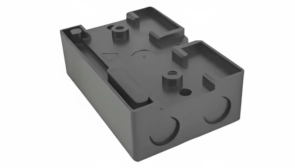
- Simplicité : Les géométries complexes avec des caractéristiques compliquées, des nervures ou des bossages sont extrêmement difficiles à remplir et doivent être réduites au minimum. La pièce idéale est simple et massive.
3. Conception de moules et d'outils :
- Capacité de haute pression : Le moule doit être fabriqué à partir d'un acier à outils à haute résistance (par exemple, P20, H13) et conçu pour résister à d'immenses pressions d'injection et de serrage sans fléchir ni se briser.
- Gates et Runners : Utiliser des glissières de grande taille et de forme arrondie pour minimiser la perte de charge. Les portes doivent être larges et alimenter directement la section la plus épaisse de la pièce. Les portillons sous-marins, les portillons à broches et autres conceptions restrictives ne sont généralement pas viables.
- Ventilation : Une bonne ventilation est essentielle pour permettre à l'air emprisonné de s'échapper au fur et à mesure que le front du matériau avance lentement. Une ventilation inadéquate peut entraîner des tirs courts et des marques de brûlure.
- Rétrécissement : L'UHMWPE présente un taux de rétrécissement élevé et souvent non uniforme. Le moule doit être conçu pour tenir compte de ce phénomène afin d'obtenir la précision dimensionnelle de la pièce finale. Cela nécessite souvent un travail de prototypage et d'itération.
4. Équipement de traitement :
- Machine à haute pression : La presse à injecter doit être capable de générer et de maintenir des pressions d'injection très élevées.
- Vis et baril : Une vis spécialisée avec un faible taux de compression (par exemple, 1,5:1 à 2,0:1) est nécessaire pour éviter la production excessive de chaleur de cisaillement, qui peut dégrader le matériau. Le cylindre et la vis doivent être en acier trempé et résistant à l'usure.
5. Coût et durée du cycle :
- Coût élevé de l'outillage : Les moules robustes à haute pression sont plus coûteux à construire que les moules standard.
- Temps de cycle longs : En raison de l'épaisseur des parois des pièces et de la thermodynamique du matériau, la phase d'injection et la phase de refroidissement sont nettement plus longues que pour les thermoplastiques conventionnels. Les temps de cycle peuvent atteindre plusieurs minutes par pièce, ce qui augmente le coût par pièce.
Fabrication de moulage par injection d'UHMWPE
Guide de fabrication pour le moulage par injection de l'UHMWPE
Ressources pour Le guide complet du moulage par injection de l'UHMWPE
Lignes directrices pour le moulage par injection de l'UHMWPE
La conception d'une pièce pour un moulage par injection réussi de l'UHMWPE nécessite le respect d'un ensemble de règles qui tiennent compte du comportement unique du matériau.
| Caractéristiques de la conception | Ligne directrice / Recommandation | Raison d'être |
|---|---|---|
| Épaisseur de la paroi | Minimum : 3 mm (0.125″) Recommandé : > 5 mm (0.200″) | S'assurer que le matériau a une trajectoire suffisamment large pour remplir la cavité avant de geler. Les parois minces sont presque impossibles à remplir. |
| Uniformité des murs | Maintenir une épaisseur de paroi aussi uniforme que possible. Si des changements sont nécessaires, ils doivent être progressifs et sans à-coups. | Empêche le refroidissement inégal, qui entraîne des déformations, des marques d'enfoncement et des tensions internes. |
| Rayons et filets | Rayon intérieur minimum : 1x l'épaisseur de la paroi. Recommandé : 2 à 3 fois l'épaisseur de la paroi. | Réduit les concentrations de contraintes, améliore l'écoulement du matériau dans les coins et rend la pièce plus résistante. |
| Côtes et bosses | À éviter si possible. Si nécessaire, faites-les courtes et épaisses. L'épaisseur de la base doit être de ~50-60% de la paroi principale. Utiliser des tirants d'air et des rayons généreux. | Ces caractéristiques sont difficiles à remplir et peuvent provoquer des marques d'enfoncement sur la surface opposée. |
| Angles d'ébauche | Minimum : 3 degrés. Recommandé : 5 degrés ou plus. | La pression de serrage élevée peut entraîner le collage de la pièce dans le moule. Un angle de dépouille généreux est essentiel pour faciliter l'éjection des pièces. |
| Trous et noyaux | Les trous doivent être éloignés des bords. La distance entre les trous ou entre un trou et un mur doit être au moins égale à deux fois le diamètre du trou. | Maintient l'intégrité structurelle et évite les problèmes d'écoulement autour des broches centrales. |
| Tolérances | S'attendre à des tolérances plus larges qu'avec les plastiques conventionnels. +/- 0,010″ est un bon point de départ, mais il dépend fortement de la géométrie. | Le taux de rétrécissement élevé et variable rend difficile le respect de tolérances extrêmement serrées. |
| Finition de la surface | Visez une finition fonctionnelle plutôt qu'une finition cosmétique. Les finitions brillantes sont difficiles à obtenir. Une finition texturée ou mate peut masquer les petites marques d'écoulement. | Le comportement d'écoulement du matériau ne se prête pas à la reproduction des textures fines du moule ou à l'obtention d'une surface de classe A parfaite. |
Comment réaliser un moulage par injection d'UHMWPE : Un guide étape par étape
Il s'agit d'un aperçu simplifié du processus spécialisé, qui met en évidence les principales différences par rapport au moulage conventionnel.
Étape 1 : Préparation du matériel :
Bien que l'UHMWPE absorbe peu d'humidité, certains grades chargés peuvent être hygroscopiques. La résine doit être séchée conformément aux spécifications du fabricant, généralement pendant 2 à 4 heures à environ 70-80°C, afin d'éviter tout défaut de surface.
Étape 2 : Installation de la machine et du moule :
Le moule est installé dans une machine de moulage par injection à haut tonnage et à haute pression. Les températures du cylindre et de la buse sont réglées. Contrairement à de nombreuses matières plastiques, le profil de température pour l'UHMWPE est relativement plat et chaud, souvent de l'ordre de 220-280°C (428-536°F). Cette température est bien supérieure au point de fusion et est nécessaire pour réduire la viscosité autant que possible.
Étape 3 : Plastication (fonte) :
Les granulés d'UHMWPE sont introduits de la trémie dans le tonneau. La vis rotative les transporte vers l'avant. La combinaison de la chaleur des bandes chauffantes du tonneau et de la chaleur de cisaillement due à la rotation de la vis commence à ramollir le matériau jusqu'à ce qu'il devienne un gel. La vitesse de rotation de la vis est faible afin de minimiser la dégradation des longues chaînes de polymères induite par le cisaillement.
Étape 4 : Injection :
Une fois que suffisamment de matière s'est accumulée devant la vis, la phase d'injection commence. La vis agit comme un piston, en poussant vers l'avant avec une force immense. Une pression d'injection extrêmement élevée (de 25 000 à plus de 40 000 psi) est appliquée pour forcer le matériau visqueux et pâteux à traverser la buse, la carotte, les canaux et l'opercule, et à pénétrer dans la cavité du moule. La vitesse d'injection est généralement lente et contrôlée pour assurer un remplissage régulier et homogène.
Étape 5 : Emballage et conservation :
Après le remplissage volumétrique du moule, une pression de "tassement" ou de "maintien" est appliquée pendant une période prolongée. Il s'agit d'une étape critique. Elle continue à pousser le matériau dans la cavité pour compenser le retrait important qui se produit lorsque le matériau refroidit et se solidifie. Une pression ou un temps de tassement insuffisants entraîneront des vides, des marques d'enfoncement et une mauvaise stabilité dimensionnelle.
Étape 6 : Refroidissement :
C'est la phase la plus longue du cycle. Comme les pièces ont des parois épaisses et que le plastique est un mauvais conducteur thermique, un long temps de refroidissement est nécessaire pour permettre à la pièce de se solidifier complètement et de devenir suffisamment stable pour être éjectée. Le moule est refroidi par une circulation d'eau ou d'huile. Si l'on précipite cette étape, on obtient un gauchissement important.
Étape 7 : Ouverture du moule et éjection :
Une fois le temps de refroidissement écoulé, le moule s'ouvre. Le système d'éjection (broches, manchons, etc.) pousse la pièce finie hors de la cavité. En raison des fortes pressions utilisées, l'éjection peut parfois être brutale.
Étape 8 : Post-traitement (si nécessaire) :
La pièce est retirée et le système de glissières/proues est découpé. En raison de la ténacité de l'UHMWPE, il est souvent nécessaire d'utiliser une scie ou une lame tranchante plutôt qu'une simple torsion ou un claquement. Dans certains cas, les pièces peuvent nécessiter un recuit post-moulage pour soulager les contraintes internes.
Quels sont les avantages du moulage par injection de l'UHMWPE ?
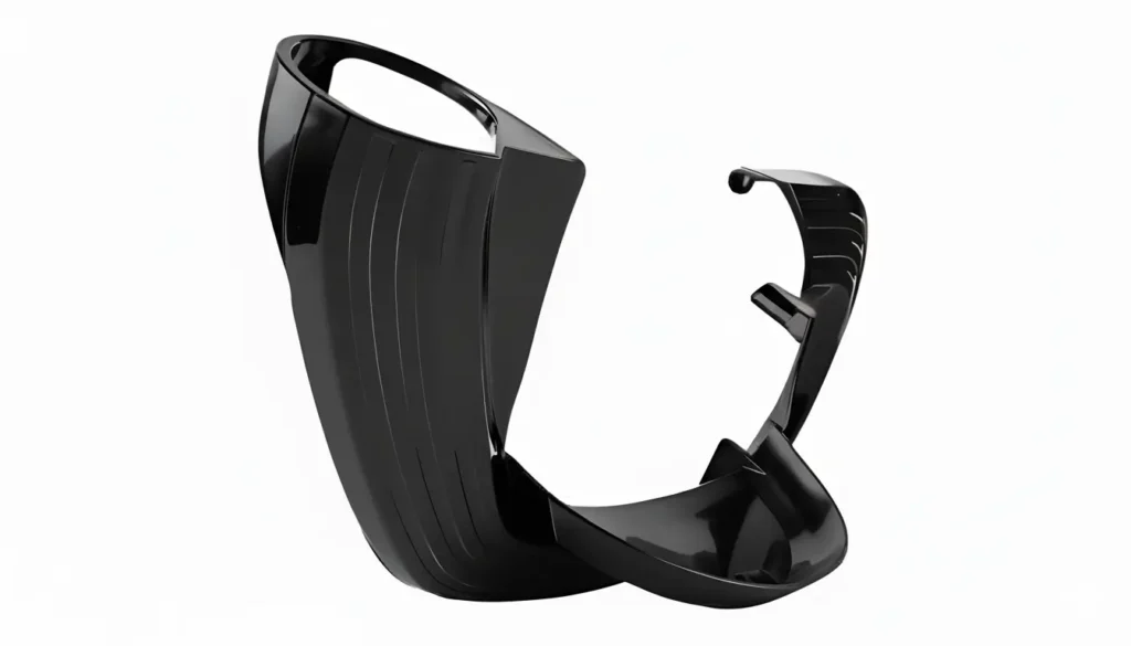
Lorsqu'il est couronné de succès, ce processus spécialisé offre des avantages significatifs par rapport à l'usinage de pièces à partir de formes en stock (barres, tôles, plaques).
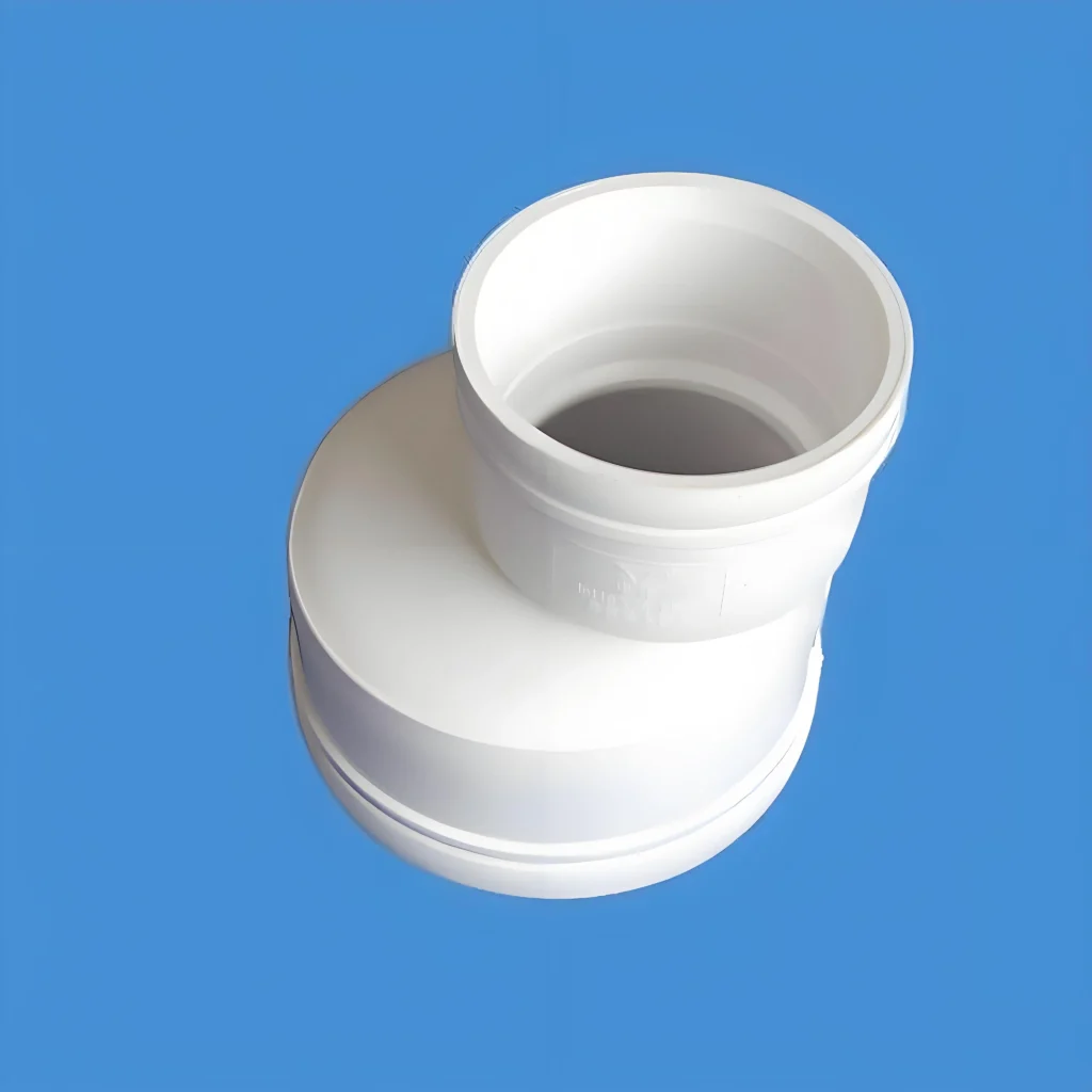
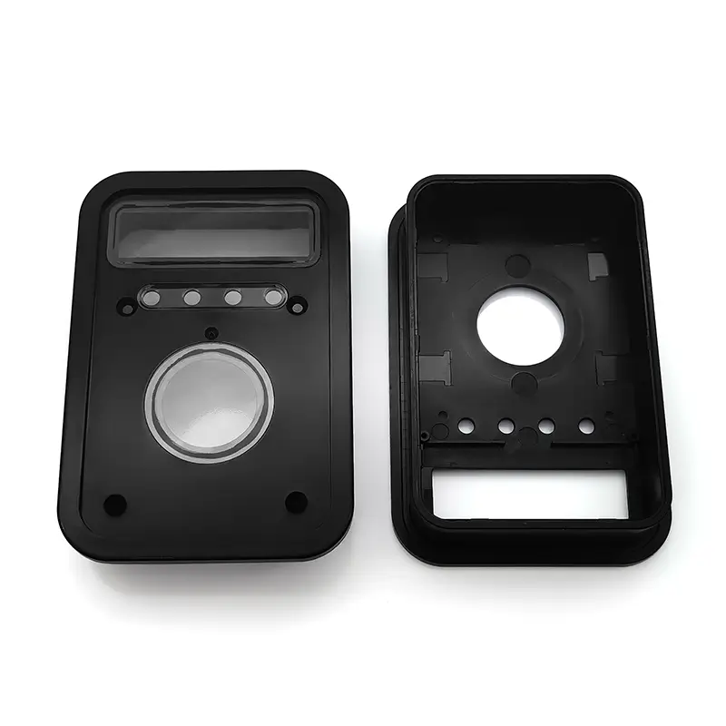
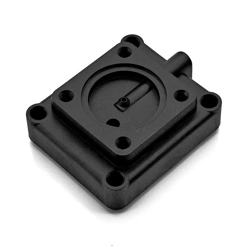
- Liberté de conception et complexité : Bien que limité par rapport à d'autres plastiques, le moulage par injection permet néanmoins de créer des pièces plus complexes et de forme plus nette que l'usinage. Les caractéristiques telles que les supports de montage intégrés, les trous borgnes et les surfaces profilées peuvent être moulées directement, ce qui réduit la nécessité d'étapes secondaires d'assemblage ou de fabrication.
- Évolutivité et production en grande quantité : Pour les séries de milliers ou de millions de pièces, le moulage par injection est beaucoup plus rentable et plus rapide que l'usinage individuel de chaque pièce. Une fois l'investissement initial dans l'outillage réalisé, le coût par pièce diminue considérablement en fonction du volume.
- Réduction des déchets matériels : L'usinage peut générer une quantité importante de déchets (copeaux), en particulier pour les pièces complexes. Le moulage par injection est un processus de forme presque nette, le seul déchet étant généralement le système de coulée, qui peut parfois être rectifié et réutilisé dans des applications spécifiques. Cela permet une meilleure utilisation des matériaux et une réduction des coûts.
- Excellente cohérence d'une pièce à l'autre : Le processus de moulage par injection est hautement reproductible. Une fois les paramètres du processus réglés, chaque pièce produite sera pratiquement identique, ce qui garantit des niveaux élevés de qualité et de cohérence, difficiles à atteindre avec des opérations d'usinage manuelles ou en plusieurs étapes.
- Amélioration des propriétés des matériaux (fusion) : Une pièce moulée par injection est formée à partir d'une masse fondue homogène, ce qui donne une structure monolithique entièrement fusionnée. Cela peut conduire à une intégrité mécanique supérieure à celle des pièces usinées à partir de pièces moulées par compression, qui peuvent parfois présenter des contraintes internes ou de légères variations de densité.
- Réduction des coûts à grande échelle : Bien que le coût initial du moule soit élevé, le faible coût du cycle (matériau + temps machine) pour des volumes importants fait du moulage par injection la méthode de fabrication la plus économique pour les grandes quantités de pièces en UHMWPE.
Quels sont les inconvénients du moulage par injection de l'UHMWPE ?
Les défis et les limites du processus sont importants et doivent être soigneusement évalués.
- Coûts d'outillage extrêmement élevés : Les moules doivent être construits pour résister à des pressions extrêmes, ce qui les rend nettement plus coûteux que les moules d'injection standard. Cet investissement initial élevé rend le procédé inadapté à la production de faibles volumes ou aux prototypes.
- Temps de cycle longs : La combinaison d'une injection lente, d'un emballage long et de temps de refroidissement prolongés signifie que les temps de cycle sont mesurés en minutes et non en secondes. Cela réduit le rendement de la machine et augmente le coût par pièce par rapport aux matériaux à cycle rapide.
- Restrictions relatives à la conception des pièces : Comme indiqué précédemment, le concepteur est limité à des géométries simples avec des parois épaisses et uniformes, des rayons généreux et de grandes dépouilles. Les parois minces, les angles vifs et les caractéristiques complexes ne sont pas réalisables.
- Difficulté de traitement élevée : Le processus a une fenêtre de fonctionnement très étroite et nécessite des machines spécialisées et des techniciens hautement qualifiés. Toutes les entreprises de moulage par injection ne disposent pas de l'équipement ou de l'expertise nécessaire pour manipuler avec succès l'UHMWPE.
- Potentiel de dégradation des matériaux : La combinaison d'une température élevée et d'un cisaillement important (dû à la vis) peut briser les longues chaînes de polymères de l'UHMWPE, ce qui réduit son poids moléculaire et compromet ses propriétés mécaniques finales. Un contrôle minutieux du processus est essentiel pour atténuer ce risque.
- Limitée Finition de la surface : Il est difficile d'obtenir une finition de surface cosmétiquement parfaite ou très brillante. De petites lignes d'écoulement, des lignes de soudure ou un aspect mat sont fréquents.
Problèmes courants et solutions dans le moulage par injection de l'UHMWPE
| Enjeu | Cause(s) potentielle(s) | Solution(s) |
|---|---|---|
| Court métrage / Remplissage incomplet | - Pression d'injection insuffisante - Température de fusion trop basse - Vitesse d'injection trop lente - Mauvaise évacuation des moisissures - Portes/coulisses trop petites | - Augmenter la pression d'injection - Augmentation de la température des canons et des buses - Augmenter la vitesse d'injection (avec prudence) - Ajout ou agrandissement d'évents dans le moule - Reconception du moule avec des patins/portes plus grands |
| Les pages de guerre | - Épaisseur de paroi non uniforme - Refroidissement inadéquat ou inégal - Temps/pression d'emballage insuffisants - Ejection de la pièce alors qu'elle est encore trop chaude | - Redessiner la pièce pour obtenir des parois uniformes - Régler le débit de l'eau de refroidissement du moule ; vérifier que les canaux ne sont pas obstrués. - Augmenter la pression et/ou la durée de l'emballage - Prolonger la phase de refroidissement du cycle |
| Marques d'affaissement / vides | - Pression ou durée d'emballage insuffisante - Les sections épaisses se refroidissent trop lentement - Température de fusion trop élevée | - Augmentation de la pression d'emballage et du temps de maintien - Éliminer les sections épaisses dans la conception de la pièce - Diminuer légèrement la température de fusion |
| Lignes de soudure | - Plusieurs fronts d'écoulement se rejoignant dans la cavité - Faible température ou pression de fusion | - Déplacer le portail pour créer une seule voie d'écoulement - Augmenter la température de la matière fondue et la pression d'injection afin d'améliorer la fusion des fronts d'écoulement. |
| Marques de brûlure | - L'air piégé dans le moule s'enflamme automatiquement sous haute pression (dieseling). - Vitesse d'injection trop élevée | - Améliorer la ventilation du moule au dernier point de remplissage - Réduire la vitesse d'injection |
| Collage de la pièce dans le moule | - Angle de tirage insuffisant - Pression de garnissage élevée - La surface du moule est trop rugueuse ou présente des contre-dépouilles | - Augmenter l'angle de dépouille dans la conception de la pièce/du moule - Réduire la pression d'emballage (équilibrer avec les éviers) - Polir l'empreinte et le noyau du moule ; vérifier l'absence de contre-dépouilles. |
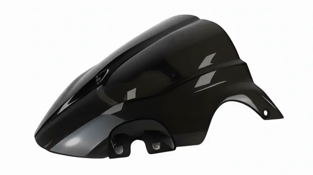
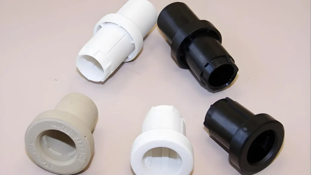
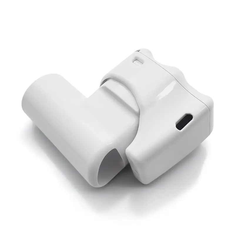
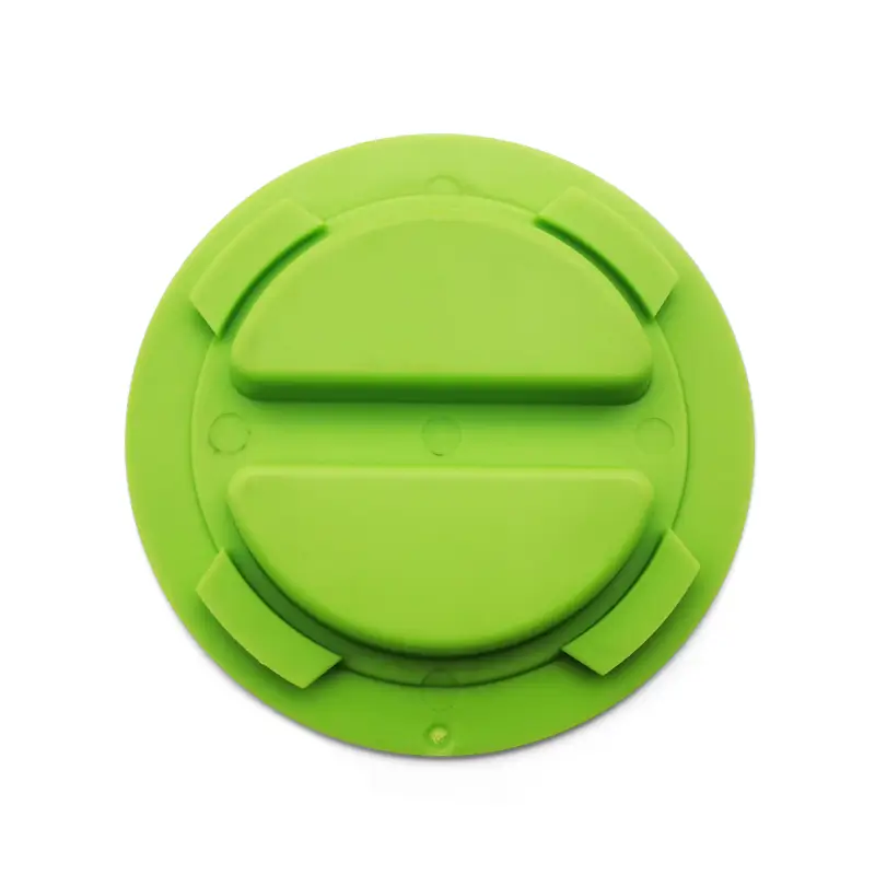
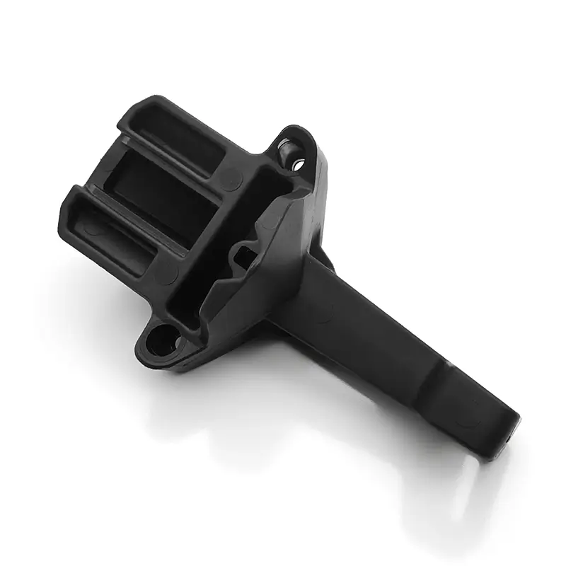
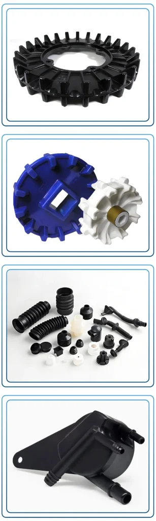
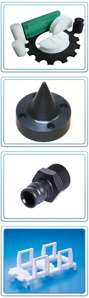
Quelles sont les applications du moulage par injection de l'UHMWPE ?
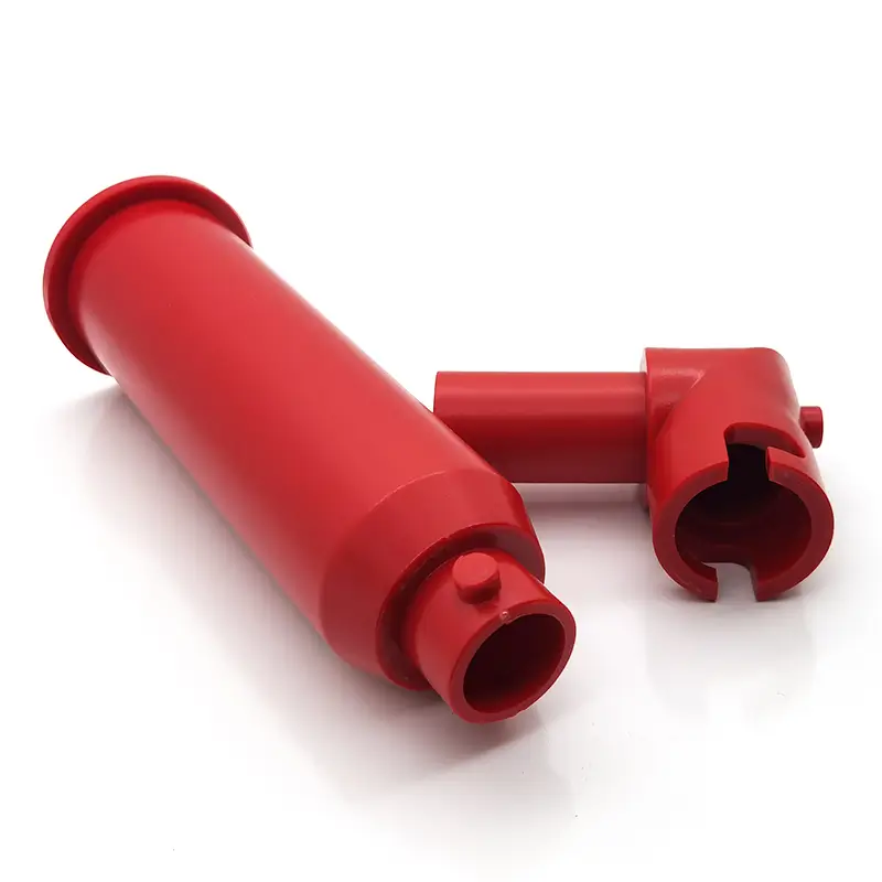
Les applications de l'UHMWPE moulé par injection se trouvent dans les industries qui exigent la production en grande quantité de composants incroyablement durables, résistants à l'usure et à faible frottement.
1. Manutention et transport des matériaux :
Il s'agit d'un marché primaire. La combinaison de la résistance à l'abrasion et du faible frottement en fait un produit idéal pour les pièces qui guident, déplacent et manipulent des produits et des matériaux en vrac.
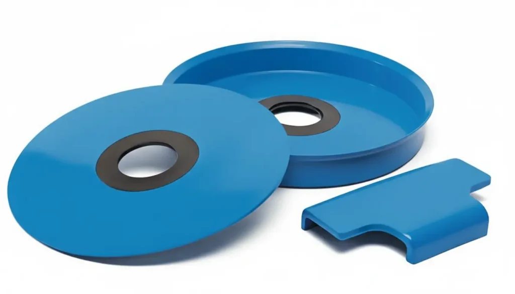
- Engrenages et pignons : Pour les systèmes de convoyage et les transmissions de puissance à faible couple. Elles sont silencieuses, autolubrifiantes et légères.
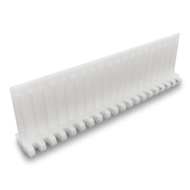
- Guides de chaîne et bandes d'usure : Guidage des chaînes à rouleaux et des bandes transporteuses avec un minimum de friction et d'usure.
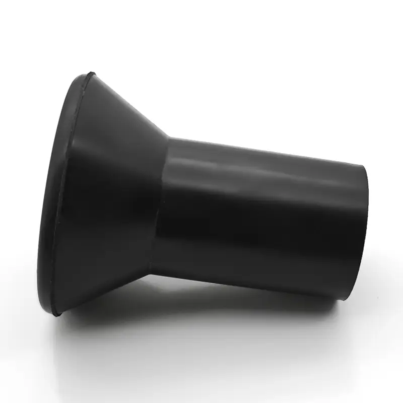
- Rouleaux et poulies : Pour les bandes transporteuses et les systèmes de câbles, offrant une surface durable et non collante.
2. Transformation des aliments et des boissons :
Les grades vierges sont conformes à la FDA, non poreux et faciles à nettoyer, ce qui les rend idéaux pour les applications en contact avec les aliments.
- Vis sans fin et vis d'alimentation : Déplacer les produits alimentaires sans les endommager ni les contaminer.
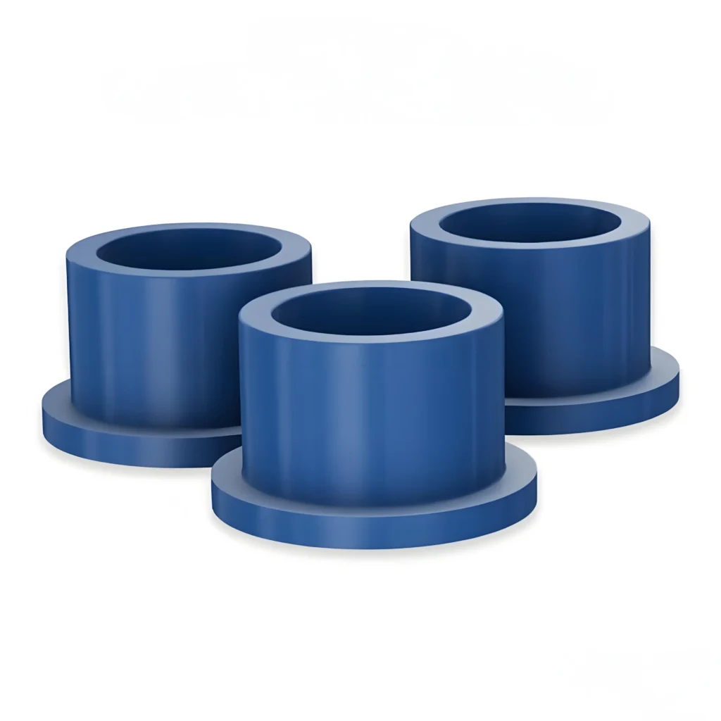
- Bagues et paliers : Pour les machines de transformation fonctionnant dans des environnements humides, corrosifs et lavés, où les roulements lubrifiés traditionnels seraient défaillants.
- Roues étoilées et rails de guidage : Utilisé dans les lignes d'embouteillage et d'emballage pour guider délicatement les conteneurs à grande vitesse.
3. Médecine et orthopédie :
Les grades biocompatibles et réticulés sont utilisés pour les dispositifs jetables à grand volume et certains composants implantables.
- Implants orthopédiques : Si les principaux composants (comme les revêtements acétabulaires dans les prothèses de hanche) sont souvent usinés à partir de matériaux réticulés, certains composants d'implants plus petits et en grande quantité peuvent être moulés par injection.
- Poignées et composants d'instruments chirurgicaux : Fournir des pièces durables et stérilisables pour les outils médicaux.
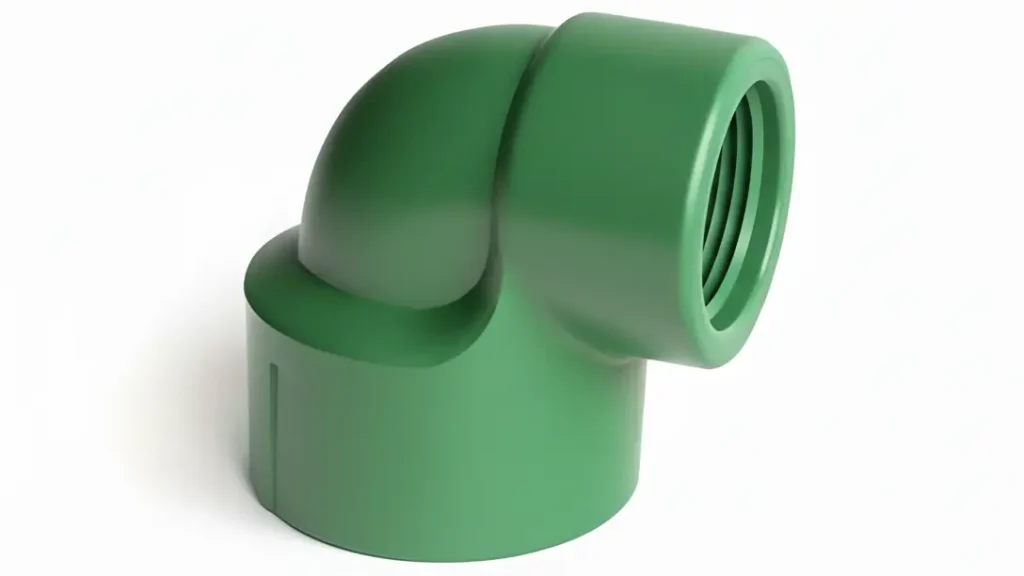
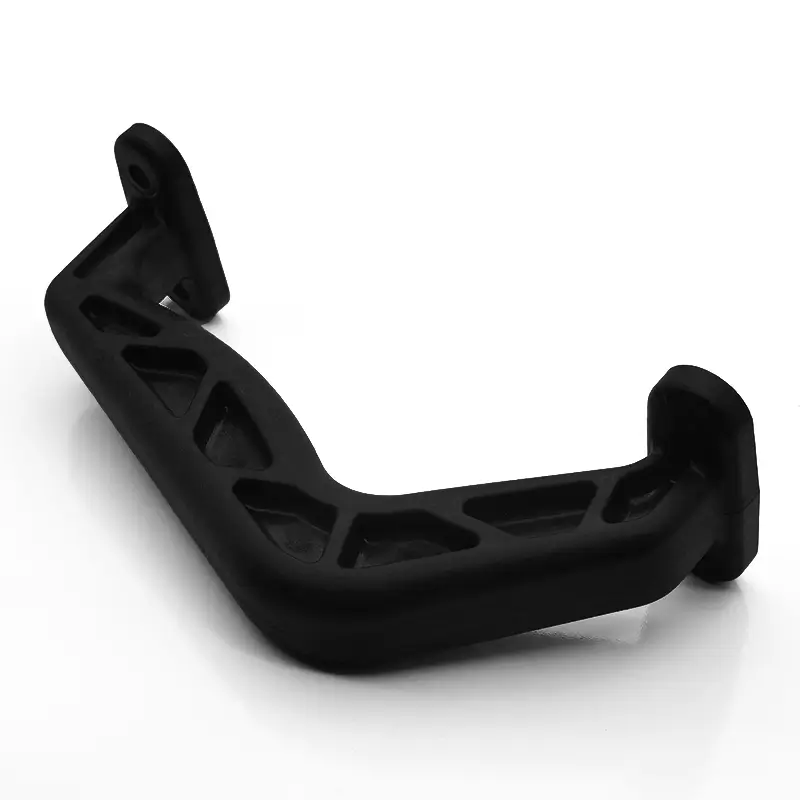
4. Machines industrielles :
- Roulements et bagues : Remplacement rentable des paliers en bronze et en nylon dans les applications à forte charge et à forte usure, en particulier dans les environnements sales ou poussiéreux.
- Joints et garnitures : Dans les applications nécessitant une excellente résistance chimique et une grande durabilité.
- Bras de prélèvement et tampons d'impact : Dans les machines automatisées où l'impact et l'usure répétés sont des préoccupations majeures.
5. Biens de consommation et de loisirs :
- Composants de ski et de snowboard : Le matériau de base des skis et des snowboards est l'UHMWPE, apprécié pour sa faible friction sur la neige.
- Roulements pour skateboards et rollers : Il offre des performances souples et durables.
- Composants d'usure des équipements de fitness : Bagues et rouleaux dans les appareils de musculation et les équipements cardio.

Metal Insert Injection Molding: Design & Defect Prevention
Key Takeaways Metal insert injection molding integrates metal components directly into plastic parts during molding for superior mechanical bond strength. Insert design—knurling, undercuts, wall thickness—is the primary driver of pull-out

Les 5 premières entreprises de moulage par injection au Pakistan
Key Takeaways Pakistan has an active plastics manufacturing sector centered around Karachi and Lahore, primarily serving domestic consumer goods, packaging, and automotive aftermarket markets. Precision injection molding capability for export-grade

What Are Geometric Tolerances in Injection Molding
Your design file says ±0.1mm. Your molder quotes ±0.2mm. Your customer requires flatness within 0.05mm across the whole sealing surface. Three different numbers — none of them speak the same
Solutions d'optimisation proposées Gratuitement
- Fournir un retour d'information sur la conception et des solutions d'optimisation
- Optimiser la structure et réduire les coûts de moulage
- Parler directement avec des ingénieurs en tête-à-tête

