 Skip to content

Key Takeaways
- Cooling accounts for 60–70% of total injection molding cycle time, making it the single largest lever for production efficiency.
- Optimal cooling channel diameter is 8–12 mm, positioned 1.5–2x the channel diameter from the cavity surface.
- Conformal cooling channels reduce cycle times by 20–40% compared to conventional straight-drilled channels on complex geometries.
- Mold temperature variation across the cavity must stay within plus or minus 5 degrees Celsius to prevent warpage, sink marks, and dimensional drift.
- Turbulent coolant flow (Reynolds number greater than 10,000) delivers 3–5x better heat transfer than laminar flow.
- ZetarMold operates 47 injection molding machines; cooling system design is the first item optimized on every new mold.
What Is Injection Mold Cooling Design and Why Does It Matter?
Injection mold cooling design is the engineering discipline of positioning cooling channels, specifying coolant flow, and balancing heat removal so a mold produces dimensionally stable parts at repeatable cycle times. Cooling typically accounts for 60–70% of total cycle time, making it the single largest controllable factor in tooling performance—a well-designed cooling system directly determines whether a mold hits dimensional tolerance and production throughput targets. For the process-side context behind these decisions, see our Injection Molding Complete Guide; this article focuses on the tooling engineering side covered in our Injection Mold Complete Guide.
| Cooling Strategy | Cost Premium | ROI Timeline |
|---|---|---|
| Standard channels | Baseline | Immediate |
| Optimized layout | +10–20% | 6–12 months |
| Conformal (3D print) | +30–50% | 12–24 months |
In one recent automotive housing project, a cooling redesign alone cut cycle time from 45 seconds to 28 seconds — a 38% reduction that saved our client over $200,000 annually. The investment in proper cooling design always repays itself within weeks on high-volume tools.
At ZetarMold, we track cooling performance across 47 injection molding machines and more than 600 production molds. On repeat programs, a cooling redesign that cuts cycle time by even 6–8 seconds typically frees one full machine shift per week at automotive volumes, which is why we review cooling before steel release instead of treating it as a press-side adjustment.
Cooling is not just about speed.
| Defect | Cooling Cause | Fix |
|---|---|---|
| Warpage | Uneven cooling | Balance coolant circuits |
| Sink marks | Insufficient cooling | Add cooling near thick sections |
| Residual stress | Rapid quench | Raise coolant temp |
Uniform heat extraction controls part dimensions, surface finish, and residual stress. A mold that cools 8°C hotter on one side than the other will produce warped parts regardless of injection pressure, pack time, or material grade. That is why thermoplastics1 processing demands cooling as a primary constraint, not an afterthought.
“Turbulent coolant flow provides 3–5x better heat transfer than laminar flow.”True
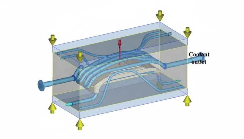
Turbulent flow (Reynolds number >10,000) creates continuous mixing that brings fresh, cooler fluid into contact with the channel walls, dramatically improving the convective heat transfer coefficient compared to laminar flow. In laminar flow, a stagnant thermal boundary layer insulates the mold steel from the coolant, reducing efficiency by a factor of 3–5. Targeting Re >10,000 is a non-negotiable starting point in our cooling circuit calculations for every new mold.
“Colder coolant always means faster cooling and shorter cycle times.”False
Excessively cold coolant causes condensation on the mold surface, introducing surface defects and rust on steel components. It also generates steep thermal gradients inside the mold, causing uneven solidification and warpage. The correct approach is to set coolant temperature above the dew point and match it to material requirements — typically 20–60°C for most engineering resins. Chasing a colder coolant temperature without considering these effects leads to higher scrap rates, not faster production.
What Are the Critical Parameters for Cooling Channel Design?
Effective cooling channel design requires six parameters balanced simultaneously: channel diameter (8–12 mm), distance to cavity surface (1.5–2x diameter), channel pitch (3–5x diameter), coolant velocity (1.5–3.0 m/s), inlet-to-outlet temperature rise (delta-T less than 5°C), and Reynolds number (greater than 10,000 for turbulent flow). Miss any one and cooling uniformity collapses regardless of how well the other five are optimized.
In our injection mold design process, we start with the 1.5-2D rule: the center of each cooling channel sits 1.5 to 2 times its own diameter away from the nearest cavity surface. Too close and the mold steel weakens, risking cracks under injection pressure. Too far and heat must conduct through excessive steel before reaching the coolant, dramatically reducing efficiency. For a 10 mm diameter channel, the channel centerline sits 15–20 mm from the part surface. In practice, we confirm this spacing together with rib depth, boss location, and ejector layout during mold design review so the cooling plan works with the rest of the tool rather than fighting it later.
How Does Coolant Velocity Affect Cooling Efficiency?
Coolant velocity is equally critical and is often set by default from the temperature control unit rather than calculated from the mold circuit.
| Simulation Tool | Key Output |
|---|---|
| Moldflow | Fill pattern, weld lines |
| Cadmould | Cooling time map |
| SigmaSoft | Thermal analysis |
At 1.5 m/s in a 10 mm channel, water achieves a Reynolds number of approximately 15,000 — solidly in the turbulent regime. Below 1.0 m/s in the same channel, flow transitions to laminar and the heat transfer coefficient drops by a factor of 3–5. When we commission a new mold, we measure actual flow rate at each circuit with a flow meter and compare it against the calculated minimum required for turbulence. This five-minute check has prevented cycle time problems on more molds than any other single commissioning step.
Cooling Channel Design Parameters
| Parameter | Recommended Value | Why It Matters |
|---|---|---|
| Channel Diameter | 8–12 mm | Smaller = higher pressure drop; larger = reduced mold strength |
| Distance to Cavity | 1.5–2x channel diameter | Too close risks breakthrough; too far reduces efficiency |
| Channel Pitch | 3–5x channel diameter | Tighter spacing improves uniformity; increases cost |
| Coolant Velocity | 1.5–3.0 m/s | Ensures Re >10,000 for turbulent flow |
| Inlet–Outlet Delta-T | Less than 5°C | Larger delta-T signals insufficient flow rate |
| Reynolds Number | Greater than 10,000 | Turbulent regime = 3–5x better heat transfer coefficient |
Channel pitch is the parameter most often neglected. We target 3–5x the channel diameter between adjacent channel centerlines. At 3x pitch with 10 mm channels, that is 30 mm center-to-center — tight enough to keep cavity surface temperature variation within ±3°C. Wider pitch saves machining cost but pushes temperature variation toward ±8–12°C, the threshold where warpage becomes a consistent rejection issue for flat parts thinner than 2 mm. In complex geometries with ribbed structures or variable wall sections, we always model pitch effects in simulation before finalizing the drilling layout to verify that the target uniformity is achievable.
“Inlet-to-outlet coolant temperature rise above 5°C signals an under-designed cooling circuit.”True
When coolant absorbs too much heat between inlet and outlet, its average temperature rises and its ability to extract heat uniformly across the cavity diminishes. A delta-T above 5°C means the flow rate is too low for the heat load, or the circuit path is too long. The fix is either to increase coolant flow, split one long circuit into two parallel shorter ones, or both. We measure delta-T on every new mold during first article inspection as a mandatory commissioning step.
“Larger cooling channels always improve heat extraction performance.”False
Channels wider than 12–14 mm reduce the structural integrity of the mold plate near the cavity surface, raising the risk of deflection or cracking under injection pressure. They also lower coolant velocity for a given flow rate, potentially shifting flow from turbulent to laminar and paradoxically worsening heat transfer. The optimal 8–12 mm range balances surface area, velocity, and mold strength. Exceeding it only makes sense when pressure drop is the critical constraint in unusually long circuits.
What Are the Main Types of Cooling Channel Layouts?
The five standard cooling layouts — straight drilled, baffle, bubbler, spiral, and conformal — each serve distinct mold geometries: straight channels suit flat cores, baffles and bubblers reach deep cavities, spiral circuits cool round cores uniformly, and conformal channels (manufactured by DMLS metal printing) follow complex 3D surfaces for maximum temperature uniformity of ±3–5°C.
Straight drilled channels are the industry baseline: a drill enters from the parting line or a side face, and plugs seal intersections. This method costs the least to machine and maintains full mold steel strength. The limitation is geometric — you can only cool what a straight drill bit can reach. For a flat lid or shallow tray, straight channels are adequate. For a housing with deep bosses and ribs, straight channels leave hot spots that drive up cycle time and warpage.
Baffles solve the deep-core problem by inserting a thin metal divider into a vertical blind hole, splitting it into two half-cylinders. Coolant travels down one side and returns up the other. Pressure drop is higher than for straight channels, but baffles are the only practical solution for long, narrow core pins where conformal cooling is too expensive. We routinely use baffles in ejector pin pockets and deep rib cores on our consumer electronics molds, achieving 15–25% cycle time reduction in those zones compared to uncooled alternatives.
Cooling Layout Comparison
| Layout Type | Best For | Advantages | Limitations |
|---|---|---|---|
| Straight (Drilled) | Simple flat geometries | Lowest cost, full steel integrity | Cannot reach complex areas |
| Baffle | Deep cores and ribs | Accesses areas drills cannot reach | Higher pressure drop |
| Bubbler | Small cores and boss pins | Effective in very tight spaces | Limited heat transfer area |
| Spiral | Round cores and cylindrical parts | Uniform circumferential cooling | Complex machining required |
| Conformal | Complex 3D shapes | 20–40% cycle time reduction possible | Requires DMLS 3D printing; higher cost |
Bubblers are miniature baffles used for very small cores where even a standard baffle insert will not fit. A central tube delivers coolant to the bottom of a blind hole and the annular gap returns it to the manifold. We use bubblers in molds for electronic connectors and medical device housings where boss diameters are 3–6 mm. Without bubblers, these features become hot spots that extend cycle time by 8–15 seconds per shot. Spiral circuits wrap a helical channel around a cylindrical core, providing even coolant coverage around the full circumference — our preferred choice for round containers and caps in 16-cavity tools.
The selection of cooling layout is as much an economic decision as an engineering one. When a project moves from concept to tooling, this is also where a disciplined injection mold manufacturing plan matters, because the best layout on paper still has to be machinable, maintainable, and robust in production. For a straightforward flat cover with uniform wall thickness, adding baffles or spirals adds machining cost without meaningful cycle time benefit — straight channels optimized with tight pitch deliver adequate uniformity. For complex housings with ribs, bosses, and compound curves, investing in baffles or conformal inserts is the only way to achieve consistent part quality within cycle time targets.
| Parameter | Recommended Value |
|---|---|
| Coolant temperature | 20–60°C |
| Flow rate | Turbulent (Re > 10,000) |
| Channel diameter | 8–12mm typical |
| Wall distance | 1.5× channel dia |
We conduct a layout audit on every new mold at the design review stage to match the complexity of the cooling circuit to the actual geometry demands.
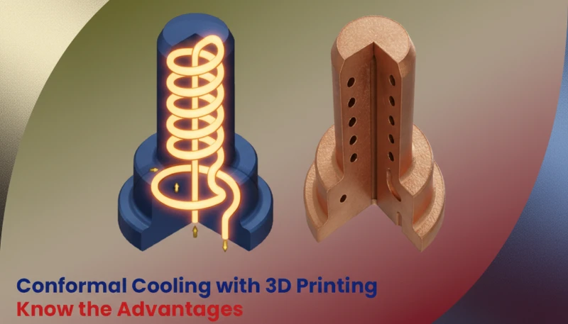
How Does Conformal Cooling Improve Injection Mold Performance?
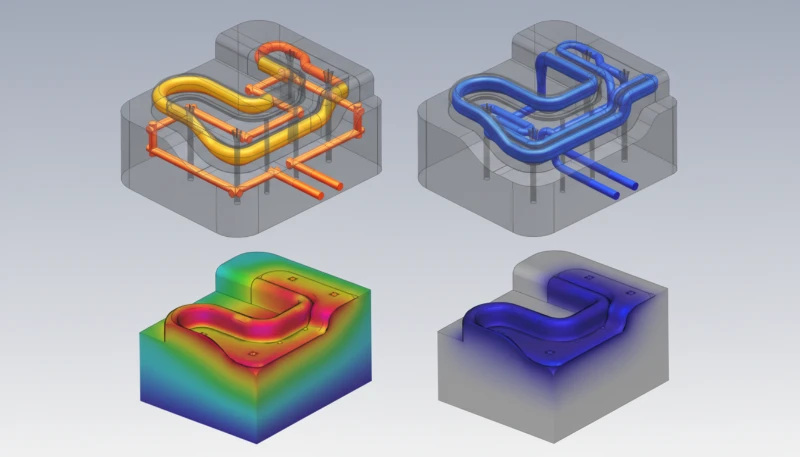
Conformal cooling channels — manufactured by Direct Metal Laser Sintering (DMLS) — follow the exact contour of the cavity surface, maintaining a constant 15–20 mm standoff distance regardless of part geometry. This constant proximity reduces peak mold temperature by 15–25°C and cuts cooling time by 20–40% versus conventional drilled channels on complex geometries.
Conventional straight channels cannot reach curved cavity surfaces uniformly. A convex dome sits 20 mm from the nearest straight channel at its apex but 45 mm at its flanks — a 2.25x variation. This causes the apex to cool far more slowly, trapping heat and extending cycle time. Conformal channels eliminate this variation by curving with the surface, keeping the distance constant. The result is temperature uniformity of ±3–5°C across the entire cavity, compared to ±10–15°C for conventional layouts on complex parts — a difference that directly prevents warpage on tight-tolerance components.
In our factory, we implemented conformal cooling on a complex automotive door trim bezel mold. The mold had a pronounced curved surface that conventional channels could not uniformly reach. With conformal inserts, cycle time dropped from 52 seconds to 31 seconds, warpage fell by 65%, and first-pass yield improved from 96.8% to 99.6%. The additional tooling cost of $18,000 for the DMLS inserts was fully recovered within 11 weeks of production.
What Are the Long-Term Benefits of Conformal Cooling Beyond Cycle Time?
An underappreciated benefit: conformal cooling’s more uniform temperature distribution reduces cyclic thermal gradients by 40–60%, extending mold life by an estimated 20–35% compared to conventional cooling. The break-even calculation depends on annual volume, cycle time savings, and machine rate. At 100,000 parts per year, saving 15 seconds per cycle frees roughly 417 machine hours annually.
| Material | Mold Temp Range | Cooling Priority |
|---|---|---|
| ABS | 40–80°C | Surface finish |
| Polycarbonate | 80–120°C | Stress reduction |
| Nylon | 60–100°C | Crystallinity |
At $80/hr machine rate, that is $33,360 per year in capacity — enough to justify conformal cooling on almost any mold with complex geometry.
For molds expected to run fewer than 50,000 parts per year, conventional cooling with carefully optimized channel placement is usually the better economic choice. For higher-volume programs, we review cooling together with injection molding cost targets so the client can see exactly when a premium insert pays back in machine-hours and scrap reduction.
The decision matrix we use weighs three factors: part complexity, annual production volume, and tolerance requirements. Only when all three are elevated — complex geometry, high volume, and tight dimensions — does the full premium of DMLS conformal cooling earn its place in the tooling budget.
For mid-volume molds with moderate geometry, targeted baffles and bubblers in the hot spots typically achieve 70–80% of conformal cooling’s cycle time benefit at 10–15% of the added cost.
Conformal vs. Conventional Cooling: Performance Comparison
| Metric | Conventional | Conformal | Improvement |
|---|---|---|---|
| Cycle Time | 45–60 sec | 28–40 sec | 20–40% faster |
| Temperature Uniformity | ±10–15°C | ±3–5°C | 3x more uniform |
| Warpage Reduction | Baseline | 40–70% less | Significant |
| Additional Tooling Cost | Baseline | 20–50% higher | Higher upfront |
| Typical ROI Timeline | — | 3–12 months | Justified at high volume |
How Does Cooling Design Affect Common Injection Molding Defects?
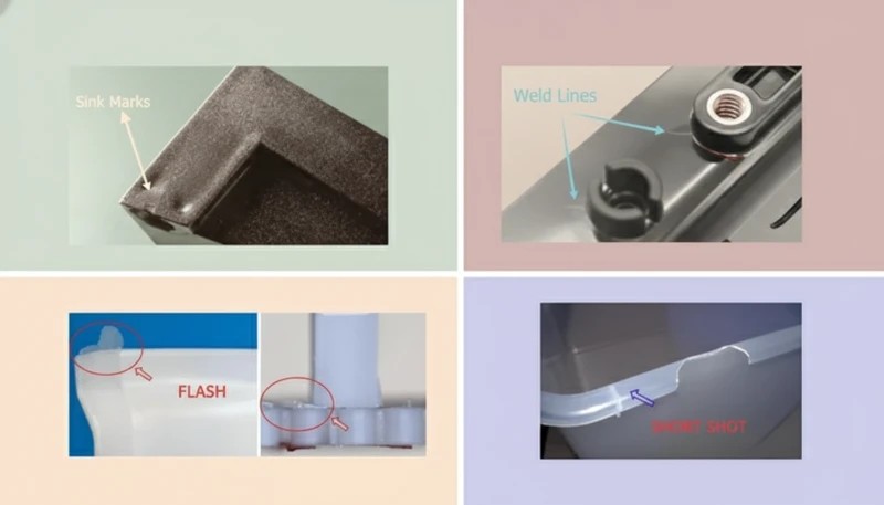
Poor cooling design directly causes warpage (temperature differentials >8°C side-to-side), sink marks (insufficient extraction at thick walls), extended cycle times (inadequate cooling capacity), and surface blemishes (condensation when coolant drops below the ambient dew point). Fixing defects at the press is always more expensive than eliminating their root cause in the cooling design stage.
Warpage is the most common cooling-linked defect. When one side of a part cools 10°C faster than the other, differential shrinkage generates internal bending stress. For a flat ABS panel 200 × 100 × 2 mm, a 10°C side-to-side temperature difference can cause 1.5–2.5 mm of bow — well beyond the ±0.3 mm tolerance typical for this part class. The fix is always the same: add cooling to the hot side, restrict it on the cool side, or redirect flow to balance circuits.
Cooling-Related Defect Troubleshooting Guide
| Defect | Cooling Root Cause | Correction |
|---|---|---|
| Warpage | Temperature differential >8°C between mold halves | Balance circuits; add channels on hot side |
| Sink Marks | Insufficient cooling at thick walls or bosses | Add localized bubblers; use BeCu inserts |
| Long Cycle Time | Inadequate overall cooling capacity | Increase channel density or flow rate |
| Surface Condensation | Coolant below ambient dew point | Raise coolant temperature above dew point |
| Dimensional Variation | Coolant temperature fluctuation >±1°C | Use a temperature-controlled unit; check flow |
| Sticking at Ejection | Part insufficiently solidified at ejection | Extend cooling time or improve heat extraction |
Sink marks at thick sections are the second most common cooling-related defect. Bosses and ribs — where the nominal wall doubles or triples — cool far more slowly than adjacent thin walls. The outer skin solidifies while the core remains molten, and as the core contracts it pulls the skin inward, creating a characteristic dimple. The solution is targeted cooling: a bubbler inside each large boss, or a beryllium copper insert to conduct heat laterally to the nearest cooling channel. We have resolved sink mark issues on over 40 molds using BeCu inserts without structural modification to the core steel.
Predicting cooling-related defects before any steel is cut is one of the highest-value investments in new mold development. Using mold flow analysis2 to run a thermal simulation with the proposed channel layout, we identify hot spots, predict temperature differentials, and calculate cooling time for each zone. This process takes 1–2 days and routinely saves 3–6 weeks of trial-and-error modifications at the press.
How Does Surface Condensation Affect Injection Mold Cooling?
Surface condensation is a less obvious but damaging cooling defect. When coolant temperature drops below the ambient dew point — typically around 16–18°C at 60% relative humidity — moisture forms on the mold surface between shots.
| Cooling Channel Type | Cycle Time Reduction | Best Application |
|---|---|---|
| Straight drilled | Baseline | Simple flat parts |
| Baffle/bubbler | 5–15% | Deep cores/bosses |
| Conformal cooling | 20–40% | Complex geometries |
This creates cosmetic surface defects (dull spots and water marks on glossy parts), accelerates surface rust on non-stainless tool steel, and can contaminate the polymer melt with moisture-related degradation. The rule is straightforward: set coolant temperature at least 3°C above the plant dew point, install a chiller with dew-point control in humid environments, and monitor with a humidity sensor mounted near the mold press. A ten-dollar sensor saves thousands of dollars in scrap and mold maintenance costs annually.
How Do You Calculate Cooling Time for Injection Molding?
Cooling time is calculated using the equation t = (s²/π²α) × ln[(4/π) × (Tm−Tw)/(Te−Tw)], where s is maximum wall thickness, α is thermal diffusivity of the resin, Tm is melt temperature, Tw is mold wall temperature, and Te is ejection temperature. The critical insight: doubling wall thickness quadruples cooling time, making wall thickness reduction the highest-leverage action available in part design.
For most engineering resins, thermal diffusivity (α) ranges from 0.08 to 0.12 mm²/s. Crystalline resins such as PP and PA release significantly more heat during solidification — due to latent heat of crystallization — than amorphous materials such as ABS or PC. A PP part at 3 mm wall thickness needs about 40–55 seconds of cooling; the same geometry in ABS needs only 25–35 seconds. Selecting the right resin for a cycle time target is as important as designing the cooling circuit itself.
In our factory, we treat any wall section thicker than 3.5 mm as a high-risk feature that automatically triggers a coring review. DFM3 at the CAD stage that catches a 4 mm wall and cores it to 2.5 mm can reduce cooling time by 50% before any tooling spend — a compounding advantage that also improves part quality, reduces material cost, and lowers warpage risk simultaneously. This is also why we pair cooling review with plastic part design: the fastest cooling channel is often a smarter part geometry, not a more expensive mold insert.
Typical Cooling Times by Wall Thickness (ABS, Mold Wall at 40°C)
| Wall Thickness | Approx. Cooling Time | Cycle Time Impact |
|---|---|---|
| 1.0 mm | 4–8 seconds | Very short; fill and pack dominate |
| 2.0 mm | 12–20 seconds | Cooling ~55% of total cycle |
| 3.0 mm | 25–40 seconds | Cooling ~65% of total cycle |
| 4.0 mm | 45–70 seconds | Cooling >70%; warpage risk rises significantly |
Frequently Asked Questions About Injection Mold Cooling Design
Below are the questions buyers and product engineers ask us most often when evaluating injection mold cooling design for a new tool or an existing production mold.
What coolant should I use for injection mold cooling?
Water is the standard coolant for injection mold cooling due to its high specific heat capacity (4.18 kJ/kg·°C), low cost, and wide availability. For mold temperatures below 15°C, water-glycol mixtures prevent freezing while maintaining acceptable heat transfer. For mold temperatures above 90°C — required for some crystalline resins and for high-gloss surfaces — oil-based temperature control units are the correct choice, as water flashes to steam at those temperatures and creates dangerous pressure surges. Match coolant type to mold temperature set point on every project before ordering temperature control hardware.
How do I detect blocked or scaled cooling channels?
The clearest indicators of blocked or scaled cooling channels are increasing cycle time over months, temperature differences exceeding 5°C between circuits that previously balanced well, and inconsistent part quality despite unchanged process parameters. Scaling (mineral deposits) builds up inside channels over time, especially in hard water regions. Schedule preventive flushing with descaling solution every 6 months on all production molds. A simple flow rate test — comparing current flow against the commissioning baseline — detects partial blockages before they cause production problems. Differential pressure measurement across each circuit identifies the exact restriction location.
Can cooling be retrofitted to an existing mold?
Limited improvements are possible without rebuilding. Unused ejector pin holes can sometimes be converted to bubblers. External cooling plates bolted to the back of the mold add surface area for heat extraction on the non-cavity side. High-conductivity BeCu inserts pressed into existing pockets improve local heat transfer without new channels. However, if the core problem is insufficient channel density near the cavity surface, meaningful improvement requires new inserts with proper channels. Major cooling redesigns typically justify building a new core or cavity insert, as the savings from improved cycle time quickly offset the cost.
What minimum clearance is required between cooling channels and ejector pins?
The standard minimum clearance between a cooling channel wall and an adjacent ejector pin hole is 5 mm in P20 or similar prehardened tool steel. For H13 hardened steel at 50+ HRC, 4 mm is acceptable due to the material’s higher crack resistance. Closer spacing risks micro-cracks between the two features after millions of thermal cycles. In practice, mold designers should flag any cooling-to-ejector-pin gap below 6 mm for a structural review, and maintain 8 mm minimum from any cooling channel to the parting line to prevent coolant leakage at high injection pressures.
How does mold steel selection affect cooling performance?
Thermal conductivity of the mold steel directly determines how fast heat travels from the cavity surface to the nearest cooling channel. P20 prehardened steel conducts at approximately 29 W/m·K, H13 tool steel at 25 W/m·K, and beryllium copper (BeCu) at 208 W/m·K — more than 7x better than P20. For hot spots in small cores or thin ribs where cooling channels cannot reach, pressing a BeCu insert into the feature dramatically improves local heat extraction. BeCu is routinely used for core pins smaller than 8 mm diameter and for thin rib features where additional channels would compromise structural integrity.
When is mold flow analysis worth the investment for cooling design?
Mold flow analysis justifies its cost on virtually every mold with cooling-sensitive specifications — any part with walls thicker than 3 mm, tight dimensional tolerances (±0.1 mm or better), cosmetic Class A surfaces, or complex geometry where hot spots are likely. The analysis costs $800–$2,500 and takes 1–2 days. A single press trial to diagnose and correct a cooling-related warpage problem costs $1,500–$5,000 in machine time and delayed shipment. No project has ever saved money by skipping simulation versus the downstream corrections it would have prevented.
If you want to review your cooling system design or discuss conformal cooling feasibility for a specific mold, contact our tooling engineering team for a design review. For the broader process and material context, see our Injection Molding Complete Guide.
-
thermoplastics: Thermoplastics are polymers that soften when heated above their glass transition or melting temperature; the term refers to a class of materials that can be repeatedly melted and solidified without chemical degradation. ↩
-
mold flow analysis: Mold flow analysis is a computer simulation technique that models polymer flow, pressure distribution, cooling time, and warpage inside an injection mold to optimize design before tooling is manufactured. ↩
-
DFM: DFM (design for manufacturability) refers to an engineering review process that evaluates product geometry for compatibility with a chosen manufacturing process, identifying features that would increase cost, reduce quality, or extend cycle time. ↩


