 Skip to content

For a complete overview, see our Injection Molding Services.
- Thin wall injection molding produces parts with wall thickness under 1.0 mm (L/T ratio above 150:1), requiring injection speeds of 500–1,500 mm/s and pressures up to 250 MPa.
- Cycle times of 2–5 seconds are achievable — 5 to 10 times faster than conventional molding — making this process cost-effective for high-volume packaging and electronics.
- Material selection is critical: polypropylene (PP) with MFI of 40–60 g/10 min and ABS or PA66+GF high-flow grades dominate thin-wall applications.
- Tool steel grade (P20 for prototypes, H13 for production runs over 500,000 cycles) and conformal cooling channels directly determine part quality and tool life.
- We run 45 injection molding machines, including dedicated high-speed presses for thin-wall work, supporting customers from DFM review through mass production.
What Is Thin Wall Injection Molding?
Thin wall injection molding is a specialized process for producing plastic parts with wall sections under 1.0 mm — defined by a flow-length-to-thickness (L/T) ratio above 150:1. At that ratio, the mold cavity is so thin that molten plastic solidifies before filling is complete unless injection speed and pressure are dramatically increased beyond conventional molding limits.
For comprehensive process guidance, see our injection molding complete guide covering materials, parameters, and defect troubleshooting.
| Metric | Thin-Wall | Conventional | Why It Matters |
|---|---|---|---|
| Wall thickness | <1.0 mm | 1.5–4.0 mm | Drives fill speed requirement |
| L/T ratio | >150:1 | <100:1 | Primary classification criterion |
| Injection speed | 500–1,500 mm/s | 50–200 mm/s | Must outrun freeze-off |
| Clamp force | 0.5–0.8 ton/cm² | 0.3–0.5 ton/cm² | Resists flash at high pressure |
In our facility, we typically classify a part as thin-wall when any section falls below 0.8 mm or when the L/T ratio exceeds 200:1. At that threshold, conventional machines simply cannot fill the cavity — the material freezes off mid-flow and you get a short shot every time. The practical wall range for most consumer packaging is 0.5–0.9 mm; electronics and medical parts can push down to 0.3 mm with the right tool geometry.
The process is not just “regular injection molding with thinner walls.” It requires dedicated equipment with accumulators, a completely different gating strategy, tighter temperature control, and — critically — a mold design that accommodates the higher clamping force needed to resist flash at elevated pressures. Every element of the system must be engineered together.

How Does Thin Wall Injection Molding Work?
The process sequence follows standard injection molding — plastication, injection, pack/hold, cooling, ejection — but every phase operates at extreme parameters. The injection phase is where thin-wall diverges most sharply from conventional work, demanding an entirely different machine specification and a tooling strategy built around rapid fill and precise thermal control.
Injection speed must reach 500–1,500 mm/s to fill the cavity before the melt front drops below the material’s no-flow temperature. For reference, conventional molding typically runs at 50–200 mm/s. The higher speed compresses the melt and generates significant shear heat, which helps offset the rapid heat loss to the cold mold wall. Timing is measured in milliseconds: a 0.5 mm wall part may fill in 0.05–0.10 seconds. On our high-speed presses, we monitor injection time in real time to detect any drift that might indicate a blocked vent or a gate that is beginning to wear.
| Phase | Thin-Wall Molding | Conventional Molding |
|---|---|---|
| Fill time | 0.05–0.15 s | 1–5 s |
| Hold time | 0.5–1.5 s | 3–10 s |
| Cooling time | 2–4 s | 10–45 s |
| Total cycle | 2–5 s | 15–60 s |
Pack and hold pressure is applied immediately after fill to compensate for volumetric shrinkage as the part solidifies. In thin-wall work, the hold phase is short — typically 0.5–1.5 seconds — because the wall freezes rapidly and additional hold time does not improve density. Over-packing is a common mistake that causes flash and sticking. In our factory, we monitor the hold-to-fill transition using in-cavity pressure sensors, cutting hold the moment pressure stabilizes — usually within 0.8 seconds of fill completion.
Cooling is the dominant phase in terms of cycle time even in thin-wall molding. Because wall thickness is small, thermal diffusion is fast — 2–4 seconds of cooling is typically sufficient to reach ejection temperature. Conformal cooling channels that follow the cavity contour, rather than straight-drilled channels, reduce temperature variation across the part by 40–60% and allow 20–30% faster cycles. For a 0.6 mm PP container, well-designed conformal cooling delivers ejection-ready parts in under 2 seconds.
“Higher injection speed reduces short shots in thin-wall molding.”True
In thin-wall parts, the melt front must reach all extremities of the cavity before the plastic solidifies. Raising injection speed from 200 mm/s to 800 mm/s reduces fill time by 75%, keeping the melt above the no-flow temperature throughout and eliminating the root cause of short shots in thin sections.
“You can use any standard injection machine for thin-wall parts.”False
Standard machines lack the accumulator-assisted injection unit needed to achieve 500–1,500 mm/s injection speeds, and their clamping systems are not designed for the high cavity pressures (140–250 MPa) required for thin walls. Using a conventional machine results in short shots, excessive flash, or machine damage.

What Are the Key Processing Parameters for Thin Wall Molding?
Thin-wall processing operates in narrow windows: any deviation from the optimal range immediately produces defects. The following parameters are the primary levers our process engineers adjust during qualification. A 5°C drop in melt temperature, a 10 MPa reduction in injection pressure1, or a 2-second delay in cooling time can shift a part from acceptable to 100% scrap — tolerances that would be inconsequential in conventional 2 mm wall molding.
| Parameter | Thin-Wall Range | Conventional Range | Effect of Deviation |
|---|---|---|---|
| Injection speed | 500–1,500 mm/s | 50–200 mm/s | Too low → short shot; too high → flash or jetting |
| Injection pressure | 140–250 MPa | 70–140 MPa | Too low → short shot; too high → flash, excessive clamp |
| Melt temperature | 220–280°C (PP) | 200–260°C | Too high → degradation; too low → freeze-off |
| Mold temperature | 15–30°C (PP) | 20–60°C | Too high → cycle time increase; too low → warpage |
| Cycle time | 2–5 s | 15–60 s | Too short → part not fully solid at ejection |
| Clamp force | 0.5–0.8 ton/cm² | 0.3–0.5 ton/cm² | Insufficient → flash at parting line |
Melt temperature control is especially critical because thin-wall sections cool 3–5 times faster than conventional parts. If melt temperature is 10°C below the recommended range, the outer skin freezes before the melt front reaches the last-fill zone, producing a short shot even at maximum injection speed. We set the barrel temperature profile so the nozzle zone is 5–10°C above the rear zone, maintaining consistent melt temperature at the gate and reducing fill inconsistency between shots.
Clamp force calculation for thin-wall tools must account for the elevated cavity pressures. The standard estimate of projected area × 0.3–0.5 ton/cm² is insufficient — use 0.5–0.8 ton/cm² for thin-wall work. An under-clamped tool will flash at the parting line even when injection parameters are correct, and simply reducing injection pressure to stop the flash will push the part into short shots instead.
| Parameter | Thin-Wall Requirement | Conventional Baseline | Key Rule |
|---|---|---|---|
| Clamp force | 0.5–0.8 ton/cm² | 0.3–0.5 ton/cm² | Calculate from projected area × 0.65 as starting point |
| Gate thickness | Match wall (0.6–0.8 mm) | 0.5–1.5 mm | Never smaller than wall thickness |
| Gate position | Thickest section | Anywhere balanced | Flow toward thin areas, not away |
| Vent depth | 0.015–0.025 mm | 0.02–0.04 mm | At last-fill points to prevent diesel effect |
Gate sizing is particularly critical in thin-wall tools. A gate that is too small restricts flow and elevates pressure drop; a gate that is too large causes jetting or weld-line defects. For walls under 0.8 mm, gate thickness should match or slightly exceed wall thickness — typically 0.6–0.8 mm — placed at the thickest section of the part to allow the melt front to progress toward thinner sections without premature freeze.
Venting is often underestimated. At 1,500 mm/s, trapped air in the cavity compresses faster than it can escape through normal parting line clearances. Dedicated vent slots (0.015–0.025 mm deep, 3–5 mm wide) at the last fill point prevent burn marks, short shots from air traps, and diesel effect — a flash-like defect caused by adiabatic compression igniting the resin.

Which Materials Work Best for Thin Wall Injection Molding?
Material selection for thin-wall parts is dominated by flow behavior. Resins must have a melt flow index2 high enough to fill the cavity before freeze-off, yet enough mechanical integrity after solidification to survive ejection without cracking. Standard resins used in conventional molding are frequently too viscous for thin-wall work.
Polypropylene (PP) is the dominant thin-wall resin, accounting for approximately 60% of all thin-wall packaging production. The ideal grade has MFI of 40–60 g/10 min (measured at 230°C/2.16 kg). High MFI grades flow easily into 0.5 mm sections but may sacrifice impact resistance; formulators balance this with nucleating agents and impact modifiers. PP’s low density (0.90–0.91 g/cm³) also reduces part weight, a key driver in packaging economics.
For structural and electronics applications, ABS high-flow grades (MFI 15–25 g/10 min at 220°C/10 kg) and PA66 reinforced with 15–30% glass fiber are preferred. The glass fiber increases stiffness significantly — from ~2.5 GPa for unfilled PA66 to 6–8 GPa for PA66+30%GF — allowing thinner walls while maintaining the structural performance required for connector housings, brackets, and enclosure panels.
| Material | MFI (g/10 min) | Min Wall (mm) | Best Applications | Key Limitation |
|---|---|---|---|---|
| PP (high-flow) | 40–60 | 0.4 | Packaging, caps, containers | Lower stiffness than engineering resins |
| ABS (high-flow) | 15–25 | 0.6 | Electronics housings, toys | Limited chemical resistance |
| PA66+GF15% | 10–20 | 0.5 | Connector housings, brackets | Moisture absorption, higher cost |
| HDPE (high-flow) | 20–40 | 0.5 | Caps, food-grade packaging | Low stiffness, prone to warpage |
| LDPE / LLDPE | 15–30 | 0.4 | Flexible lids, closures | Not suitable for rigid structures |
One material decision point that surprises many buyers: using the same resin grade as in your conventional tools will likely not work in a thin-wall tool. We frequently see customers bring a PP grade with MFI 12 g/10 min that runs perfectly in a 2 mm wall part but causes 100% short shots in a 0.7 mm wall tool. Resin qualification is a mandatory step, not an afterthought — budget one to two weeks for material trials before tool sign-off.
How Should You Design a Mold for Thin Wall Parts?
Thin-wall mold design deviates from conventional practice in five critical areas: gate design, cooling system, venting, ejection, and steel selection. Getting any one of these wrong will produce either a defective part, a broken tool, or an unacceptably long cycle time.
Gate design drives fill balance and weld line location. For rectangular thin-wall parts like food containers, a film gate running along the full width of one edge gives the most uniform fill front and eliminates weld lines entirely. Fan gates work well for smaller parts. Point gates (hot or cold) at the thickest feature — typically a boss or rib — direct the melt toward thinner areas, but require careful simulation to avoid weld lines at visible surfaces.
| Volume | Recommended Steel | Hardness | Cost vs. P20 |
|---|---|---|---|
| <50,000 shots | Aluminum (QC-10) | N/A | 30–50% less |
| 100,000–500,000 shots | P20 pre-hardened | 30–36 HRC | Baseline |
| >1,000,000 shots | H13 hot-work tool steel | 48–52 HRC | 15–25% more |
| >5,000,000 shots | H13 + PVD coating | 58–62 HRC surface | 25–40% more |
Steel selection is determined by production volume. For prototype runs under 50,000 shots, aluminum (Alcoa QC-10 or equivalent) machines faster and costs 30–50% less than steel tooling. For production volumes of 100,000–500,000 shots, P20 pre-hardened steel (30–36 HRC) is the workhorse choice. For high-volume runs exceeding 1,000,000 shots — typical in packaging — H13 hot-work tool steel hardened to 48–52 HRC is required. H13 resists the higher contact stress from elevated cavity pressures and maintains dimensional accuracy over millions of cycles.
“Conformal cooling channels are worth the added mold cost for thin-wall production.”True
Conformal cooling channels follow the cavity contour, reducing temperature variation from ±15°C to ±5°C and enabling 20–30% faster cycles. At 10 million shots per year on a packaging line, a 20% cycle time reduction translates to 2 million additional parts annually — easily justifying the 15–25% higher mold cost.
“Standard mold steel P20 is sufficient for all thin-wall production volumes.”False
P20 (30–36 HRC) is adequate for prototype and medium-volume work up to approximately 500,000 shots. Above that threshold, the elevated cavity pressures in thin-wall molding (up to 250 MPa) cause accelerated wear and dimensional drift. H13 at 48–52 HRC is required for high-volume production to maintain gate and cavity dimensions through millions of cycles.
What Are the Common Defects in Thin Wall Injection Molding and How to Prevent Them?
Thin-wall parts are highly sensitive to process variation. The same root cause that produces a barely acceptable part at nominal conditions creates a 100% defect rate when one parameter drifts by 10%. Understanding the specific failure modes allows engineers to set tight process alarm limits and prevent downtime. In our quality system, all thin-wall tools are fitted with cavity pressure sensors that trigger automatic part rejection when peak pressure deviates more than ±5% from the nominal value — catching short shots and flash before they reach the quality inspection stage.
The following table summarizes the seven most common defects we encounter on thin-wall tools, along with their root causes and the corrective actions that reliably fix them. Note that several defects share symptoms but require opposite interventions — correctly identifying the root cause before adjusting parameters saves significant troubleshooting time.
| Defect | Root Cause | Prevention |
|---|---|---|
| Short shot | Insufficient speed/pressure; freeze-off before fill complete | Increase injection speed; optimize gate size; increase melt temp |
| Flash | Excessive injection pressure; insufficient clamp force; worn parting line | Reduce pack pressure; verify clamp tonnage; inspect parting line |
| Warpage | Non-uniform cooling; unbalanced flow; residual stress | Conformal cooling; balanced runner; symmetrical gate placement |
| Sink marks | Insufficient pack pressure; premature gate freeze | Increase hold pressure/time; enlarge gate; raise mold temperature |
| Weld lines | Multiple flow fronts meeting without sufficient heat | Relocate gate; increase melt temperature; reduce wall variation |
| Burn marks | Trapped air; excessive injection speed in end-fill zone | Add venting at last-fill locations; reduce speed in final 5–10% of fill |
| Jetting | Gate too small; high injection speed with poor gate design | Use film or fan gate; increase gate diameter; reduce injection speed at gate |
“Identifying the root cause of a defect before adjusting process parameters is essential in thin-wall troubleshooting.”True
Several thin-wall defects share visible symptoms but require opposite corrective actions. Weld lines and sink marks can both appear as surface depressions — increasing pack pressure addresses a sink mark but does nothing for a weld line’s root cause (gate location and melt temperature). Similarly, flash and short shots are caused by opposite conditions: excess pressure vs. insufficient pressure. Misdiagnosing the defect and adjusting in the wrong direction typically makes the problem worse, wastes machine time, and can damage tooling.
“The same process settings can be used for thin-wall injection molding across packaging, electronics, and medical applications.”False
Each application segment requires fundamentally different process parameters and quality requirements. Packaging optimizes for maximum throughput and minimum material cost (simple QC, FDA resin compliance). Electronics demands Class A surface quality with tight dimensional tolerances (±0.1 mm). Medical applications require IQ/OQ/PQ process validation, clean-room production, and biocompatible resins (USP Class VI). Automotive parts need PPAP qualification and IATF 16949 controls. A single process window does not serve all these segments — material selection, validation protocols, and QC rigor differ substantially.
In our production experience, the most frequently misdiagnosed thin-wall defect is a weld line mistaken for a sink mark. A weld line appears as a visible seam on the surface, often with a slight depression. Operators sometimes increase pack pressure, which fixes the depth but not the seam visibility. The real fix is to reposition the gate so both flow fronts merge at a non-visible surface, or to run a mold flow analysis3 simulation before the tool is cut to predict and eliminate weld line locations during the design phase rather than after production has started.
Controlling Flash in Thin-Wall Tools
Flash prevention requires a systematic approach. Beyond adjusting injection parameters, you need to verify that clamp tonnage is correctly calculated — for thin-wall parts, use the projected area of the cavity multiplied by 0.5–0.8 ton/cm² rather than the conventional 0.3–0.5 ton/cm². Under-clamped thin-wall tools flash at low pack pressure; increasing pressure to fill properly just makes the flash worse. If a tool consistently flashes even at low pack pressure, check the clamp force calculation first before adjusting any other parameter. A digital clamp force indicator at the platen provides the most accurate measurement.
Where Is Thin Wall Injection Molding Used?
Thin wall injection molding is the dominant manufacturing process for high-volume, lightweight plastic goods across five major market segments — food and beverage packaging, consumer electronics, medical devices, automotive interiors, and industrial closures. Each segment has distinct wall thickness requirements, material specifications, quality standards, and production scale requirements that directly influence tool design, material selection, process qualification, and ongoing production control strategies.
| Industry | Typical Wall (mm) | Key Material | Volume/Year |
|---|---|---|---|
| Food & beverage packaging | 0.5–0.8 | PP (FDA grade) | Billions of units |
| Consumer electronics | 0.8–1.2 | ABS / PC-ABS | Hundreds of millions |
| Medical disposables | 0.3–0.7 | PP / PE (USP VI) | Billions of units |
| Automotive interior | 1.0–1.5 | PA+GF / PBT | Tens of millions |
| Industrial caps & closures | 0.6–1.0 | PP / HDPE | Billions of units |
Market-Specific Requirements at a Glance
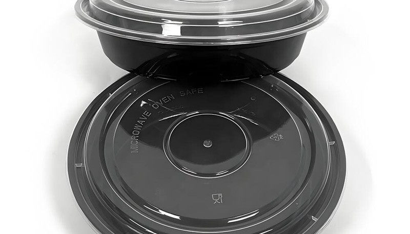
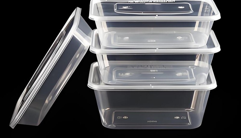
Food and beverage packaging accounts for the largest volume by far. PP thin-wall containers for yogurt, deli items, and ready meals are produced at very high rates of 10,000–50,000 cycles per day per cavity. Wall thickness is typically 0.5–0.8 mm. FDA-compliant PP grades meeting 21 CFR requirements are standard; no heavy metal stabilizers, no BPA. The economics are compelling: a 0.6 mm wall container uses 25–30% less material than a 0.9 mm wall equivalent.
Consumer electronics enclosures represent the second-largest thin-wall segment. Smartphone housings, laptop palms, and tablet backs require walls of 0.8–1.2 mm in ABS or PC/ABS blends to achieve Class A surface quality with embedded snap features and living hinges. Dimensional tolerances are tight — typically ±0.1 mm — and surface finish must be free of flow marks, which demands careful gate placement and mold flow simulation before tooling. Post-mold operations including pad printing, ultrasonic welding, and surface coating require part-to-part consistency that thin-wall processes deliver when properly validated.
| Segment | Key Standard | Critical Requirement |
|---|---|---|
| Food packaging | FDA 21 CFR | Resin compliance, no BPA |
| Medical devices | USP Class VI / ISO 10993 | Biocompatibility, process validation |
| Automotive | IATF 16949 | PPAP, Cpk ≥1.67 |
| Electronics | RoHS / REACH | Halogen-free materials |
Medical disposables — syringe barrels, pipette tips, diagnostic cartridges, and microfluidic chips — require both thin walls (0.3–0.7 mm) and biocompatible materials (USP Class VI certified resins). Clean-room production and validated processes (IQ/OQ/PQ qualification protocols) add cost but are non-negotiable for regulated markets. Automotive interior parts (clip housings, connector brackets, door panel inserts) complete the picture, demanding PA or PBT with high glass fiber content for the structural rigidity required in underhood and cabin environments up to 140°C.

For tooling strategy and mold design considerations, see our injection mold complete guide.
Factory Insight: Thin-Wall Molding at ZetarMold
In our Shanghai facility, we run thin-wall programs across 45 machines (90T–1850T) with 20+ years of production experience. Thin-wall parts below 1.0 mm wall thickness require precise injection speed control—too slow and the part shorts, too fast and flash appears. Our standard approach for new thin-wall programs is to simulate first, validate gate placement, then set conservative injection profiles that we tighten over the first 50 qualification shots. This disciplined ramp-up eliminates the most common thin-wall startup issues before production volume begins.
Frequently Asked Questions About Thin Wall Injection Molding
What wall thickness qualifies as ‘thin wall’ in injection molding?
A part is classified as thin-wall when any cross-section is below 1.0 mm with a flow-length-to-thickness (L/T) ratio above 150:1. In practice, most packaging applications fall in the 0.5–0.8 mm range. Parts with walls of 1.0–1.5 mm and high L/T ratios (150:1–200:1) occupy a transitional zone that requires some thin-wall process adjustments but not necessarily dedicated thin-wall equipment. The L/T ratio is the more reliable classification criterion: a long, slender 1.2 mm section can behave like a true thin-wall part during fill.
How fast is thin wall injection molding compared to standard molding?
Cycle times for thin-wall parts are typically 2–5 seconds, compared to 15–60 seconds for conventional injection molding — a 5–10× speed advantage. This is driven by rapid heat dissipation from thin cross-sections, which cuts cooling time dramatically. For high-volume thin-wall packaging runs at 12,000–15,000 shots per hour on multi-cavity tools, producing over 100,000 finished parts per hour on a 16-cavity tool. On an annual basis, this speed advantage translates directly to lower per-part cost and faster response to demand spikes.
What injection pressure is required for thin wall parts?
Thin-wall injection molding requires injection pressure of 140–250 MPa, compared to 70–140 MPa for conventional molding. The elevated pressure is necessary to drive high-flow-rate melt into very thin cavities before freeze-off occurs. Machines must be equipped with accumulators or servo-driven injection units to achieve the rapid pressure buildup required — conventional hydraulic machines cannot respond fast enough. Cavity pressure sensors are strongly recommended to monitor and control the actual pressure inside the mold, not just the hydraulic pressure at the machine.

Can I use my existing injection molding machine for thin wall parts?
Usually not without significant upgrades. Standard machines lack the accumulator-assisted injection unit needed to achieve 500–1,500 mm/s injection speeds. The injection unit response time on a conventional machine is too slow — by the time full pressure builds, the thin section has already started to freeze. Dedicated thin-wall presses from Husky, Netstal, or Engel with servo-electric or accumulator-hydraulic systems are required for consistent production. Some processors retrofit an accumulator to an existing machine, which can work if the injection speed and response time are verified post-retrofit.
What is the minimum wall thickness achievable with injection molding?
The minimum achievable wall thickness in production injection molding is approximately 0.3 mm, using high-flow PP or LCP resins in precision tools with localized heating. Walls of 0.5–0.6 mm are more routinely achievable across a range of materials. Factors limiting minimum wall thickness include material viscosity at fill temperature, the distance from gate to last-fill point (flow length), mold temperature uniformity, and available injection pressure. Below 0.3 mm, micro-injection molding with specialized equipment — barrel volumes under 1 cm³, precision screws — is required to maintain dimensional consistency.
Does thin wall injection molding require special mold steel?
Yes. For prototype and low-volume work under 50,000 shots, aluminum tooling (Alcoa QC-10 or equivalent) is cost-effective and machines faster. For medium production runs of 100,000–500,000 shots, P20 pre-hardened steel (30–36 HRC) is the standard choice. For high-volume production above 1,000,000 shots — typical in packaging — H13 hot-work tool steel hardened to 48–52 HRC is required to resist the higher cavity pressures up to 250 MPa and maintain dimensional accuracy over millions of cycles without gate wear or cavity distortion.
Bottom line: Thin-wall injection molding works when L/T ratio, machine capability, and mold cooling are all engineered together. Parts below 1.0 mm wall thickness require simulation before steel, dedicated high-speed machines, and conformal cooling—not just faster injection on standard tooling. If your part qualifies, cycle times of 5–15 seconds are achievable; if it doesn’t, wall thinning the design is the right first step.
Planning a thin-wall program? Contact us or explore our injection molding services for high-speed thin-wall expertise.
-
injection pressure: Injection pressure refers to the hydraulic pressure applied by the injection unit to push molten plastic into the mold cavity, measured in MPa; in thin-wall molding it typically ranges from 140 to 250 MPa. ↩
-
melt flow index: Melt flow index (MFI) is a measure of the ease of flow of a molten polymer, expressed in grams per 10 minutes (g/10 min) at a specified temperature and load under ASTM D1238 or ISO 1133. ↩
-
mold flow analysis: Mold flow analysis is a computer simulation technique that predicts how molten plastic fills a mold cavity, identifying potential defects such as short shots, weld lines, and sink marks before tooling is cut. ↩


